Advantech PCI-1712 Manual
Advantech
Ikke kategoriseret
PCI-1712
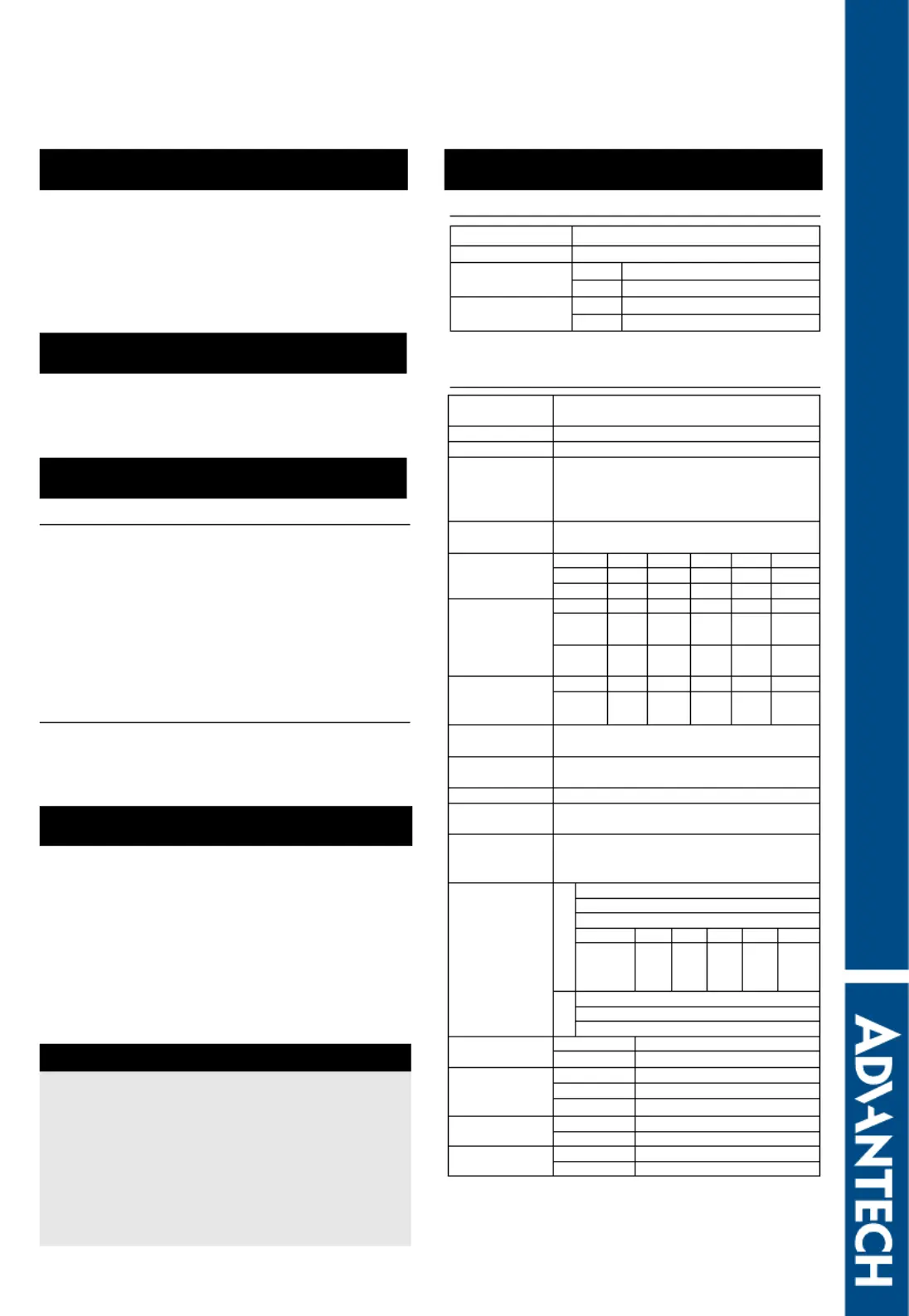
| Mærke: | Advantech |
| Kategori: | Ikke kategoriseret |
| Model: | PCI-1712 |
Har du brug for hjælp?
Hvis du har brug for hjælp til Advantech PCI-1712 stil et spørgsmål nedenfor, og andre brugere vil svare dig
Ikke kategoriseret Advantech Manualer

31 Oktober 2025
7 Oktober 2025
7 Oktober 2025
7 Oktober 2025
7 Oktober 2025
7 Oktober 2025
7 Oktober 2025
7 Oktober 2025
7 Oktober 2025
2 Oktober 2025
Ikke kategoriseret Manualer
- Bioogród
- Angler
- PeakTech
- Alcatel
- MJX
- On-Stage
- Zaahn
- Ei Electronics
- TecTake
- Lauten Audio
- Chuango
- Hyundai
- Crane Song
- Sekonic
- Gerlach
Nyeste Ikke kategoriseret Manualer
2 November 2025

2 November 2025

2 November 2025
2 November 2025
2 November 2025
2 November 2025
2 November 2025
2 November 2025

2 November 2025
2 November 2025