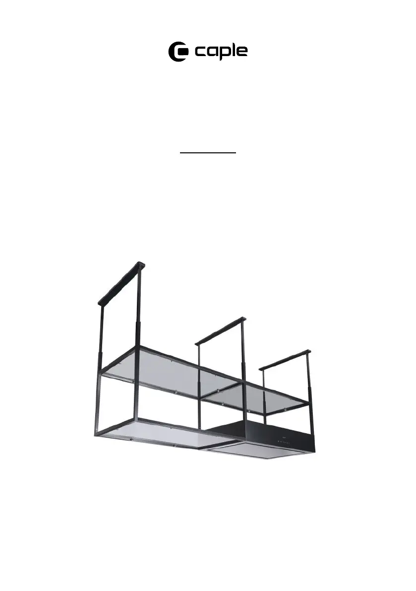
Caple Tela TEL900 Manual
Læs gratis den danske manual til Caple Tela TEL900 (48 sider) i kategorien Emhætte. Denne vejledning er vurderet som hjælpsom af 14 personer og har en gennemsnitlig bedømmelse på 4.5 stjerner ud af 7.5 anmeldelser.
Har du et spørgsmål om Caple Tela TEL900, eller vil du spørge andre brugere om produktet?
Produkt Specifikationer
| Mærke: | Caple |
| Kategori: | Emhætte |
| Model: | Tela TEL900 |
| Type: | Ø |
| Bredde: | 900 mm |
| Produktfarve: | Sort |
| Kontroltype: | Berøring |
| Antal hastigheder: | 4 |
| Indbygget skærm: | Ja |
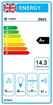
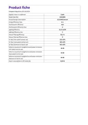
| Årligt energiforbrug: | 96 kWh |
| Timer: | Ja |
| Lampetype: | LED |
| Støjniveau: | 69 dB |
| Pæreeffekt: | 4 W |
| Antal lyskilder: | 2 pære(r ) |
| Maksimal ekstraktionseffekt: | 605 m³/t |
| Fedtfilter type: | Aluminium |
| Ekstraktionstype: | Aftræk/Recirkulerende |
| Højde (min.): | 580 mm |
| Højde (maks.): | 1180 mm |
| Væske - dynamisk effektivitetsklasse: | D |
| Lys - effektivitetsklasse: | D |
| Fedt - filtrering effektivitetsklasse: | D |
| Minimum afstand fra elektrisk komfur: | 650 mm |
| Minimum afstand fra gaskomfur: | 760 mm |
| Dybde (min.): | 550 mm |
Har du brug for hjælp?
Hvis du har brug for hjælp til Caple Tela TEL900 stil et spørgsmål nedenfor, og andre brugere vil svare dig
Emhætte Caple Manualer


Emhætte Manualer
- Meireles
- Blaze
- Samus
- HomeCraft
- Siku
- Turbo Air
- Bellini
- Ikea
- Sedona
- Twin Eagles
- Zanker
- Marynen
- Ariston
- Applico
- BlueStar
Nyeste Emhætte Manualer


