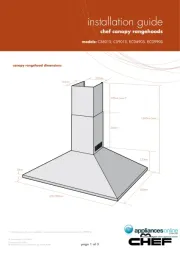
Chef CS602S Manual

Chef Emhætte CS602S

Læs gratis den danske manual til Chef CS602S (4 sider) i kategorien Emhætte. Denne vejledning er vurderet som hjælpsom af 30 personer og har en gennemsnitlig bedømmelse på 5.0 stjerner ud af 15.5 anmeldelser. Har du et spørgsmål om Chef CS602S, eller vil du spørge andre brugere om produktet?

Side 1/4
AR500FS
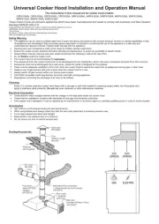
Rear Exhaust
to atmosphere
Side Exhaust
to atmosphere
Recirculating
Installation
Top Exhaust
to atmosphere
AR125RC
AR125F
AR125FD
Roof cowl
Flue
1200mm length
Alternative flue connection
1 metre flexible duct with joiners
Flashing
Not Supplied
90º bend
AR125B
AR500RK
AR125WV
Wall vent
(includes 400mm of flue)
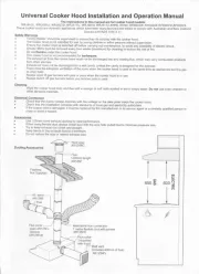
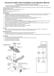
600-900 Canopy Installation and Operation Manual
The instructions in this manual are for cooker hood models: CS601S,CS602S, CS902S, CS901S, WRF600, WRF600CS, WRF900CS,
WRG630CW,WRG630CS,WRG930CW,WRG930CS,RCD690S,RCD990S
Safety Warnings
Electrical Connection
Accessories
Cleaning
Part Numbers: Description:
These cooker hoods are domestic appliances which have been manufactured and tested to comply with Australian and New Zealand
Standard AS/NZS 3350.2.31.
These appliance are intended to be used in household and similar applications such as: Staff kitchen areas in shops, ofces and other
working environments; Farm Houses; By clients in hotels, motels and other residential type environments; Bed and breakfast type
environments.
This appliance is not intended for used by persons (including children) with reduced physical, sensory or mental capabilities, or lack of experience
and knowledge, unless they have been given supervision or instruction concerning use of the appliance by a person responsible for their safety.
Children should be supervised to ensure that they do not play with the appliance.
Ensure the cooker hood is switched o before carrying out maintenance, to avoid any possibility of electric shock.
Grease lters must be removed every four weeks (maximum) for cleaning to reduce the risk of re.
Do not amb’e under the cooker hood.
This cooker hood is not recommended for barbeques.
The exhaust air from the cooker hood must not be discharged into any heating ue, which may carry combustion products from other sources.
Exhaust air must not be discharged into a wall cavity, unless the cavity is designed for the purpose.
There must be adequate ventilation of the room when the cooker hood is used at the same time as appliances burning gas or other fuels.
Always cover lit gas burners with pots or pans when the cooker hood is in use.
Always switch o gas burners before you remove pots or pans.
CAUTION: Accessible parts may become hot when used with cooking appliance.
Regulations concerning the discharge of air have to be fullled.
Check that the mains voltage matches with the voltage on the data plate inside the cooker hood.
Check that the installation complies with standards of local gas and electricity authorities.
If the supply cord is damaged, it must be replaced by the manufacturer or its service agent or a similarly qualied person in order to avoid a hazard.
Use 125mm round exhaust ducting for best performance.
When using exible duct always install duct with the wire helix pulled taut to minimise pressure loss.
Try to keep exhaust duct short and straight.
Keep bends in the exhaust duct to a minimum.
Do not reduce the size or restrict exhaust duct.
Wipe the cooker hood body and ue with a sponge or soft cloth soaked in warm soapy water. Do not use oven cleaners or other abrasive materials.
AR125RC
AR125B
AR125F
AR125FD
AR125VW
AR500FS
AR500RK
AR500CF
Roof Cowl
90º Bend
Flue 1200mm Long
Flexible Duct - 1 Metre Long When Expanded
Wall Vent Kit
Extra Length Flue Cover 1100mm Length Brushed Stainless Steel
Recirculating Kit
Replacement Carbon Filters
DUCTING ACCESSORIES
INSTALLATION OPTIONS
Page 1
203203
(600 model)
(600 model)
C
L
Hood base
Top of hob
MINIMUM:
600 electric
650 gas
MAXIMUM:
800 mm
245
75 75
65 65
38 303303
600 models as per this diagram with these dimensions the only variables
490
B
Page 2
Warning: Failure to install the screws or xing device in accordance with these instructions may result in electrical hazards.
COMPONENTS LIST
COMPONENTS NOT INCLUDED
Diagram B:
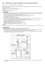
INSTALLING THE COOKER HOOD
NOTE:
NOTE:
1 body assembly with grease lters
(900-3 grease lters / 600-2 grease lters)
1 telescopic ue cover set
2 cover ue mounting brackets
1 instruction book
1 plastic bag containing screws for xing
telescopic ue covers
1 plastic duct transition: oblong to round
Fixings required to attach cover ue
mounting brackets to wall
Fixings required to attach the cooker hood
to wall
Recommended working heights.
Cover ue mounting bracket locations.
Telescopic cover ue xing points.
Before installing the cooker hood, peel o any
protective plastic covering.
Remove polystyrene packaging from inside
behind fan motor.
(Diagrams C )
Some installations may require telescopic
ue cover cut to length. Cut with tin snips or
a ne-tooth hack saw blade, taking care not
to distort or dent ue cover.
The maximum space between the wall and
screw top is 5mm.
If the instructions of the hob
specify a greater distance than
the minimum, then that shall
be the minimum height for the
installation
DIMENSIONS ARE IN MILLIMETRES
A
222
165
230
500
600/900
20
max)
1240(
540
470(max)
C


Produkt Specifikationer

Mærke: Chef
Kategori: Emhætte
Model: CS602S

Har du brug for hjælp?

Hvis du har brug for hjælp til Chef CS602S stil et spørgsmål nedenfor, og andre brugere vil svare dig


Emhætte Chef Manualer
Chef

Chef REHR6S Manual

4 September 2024
Chef

Chef RRE635W Manual

4 September 2024
Chef

Chef REHR6W Manual

4 September 2024
Chef

Chef RRE934S Manual

4 September 2024
Chef

Chef RRE634W Manual

4 September 2024
Chef

Chef RFD602W Manual

4 September 2024
Chef

Chef RFD902S Manual

4 September 2024
Chef

Chef RFD902W Manual

4 September 2024
Chef

Chef CRI714DB Manual

20 Juni 2024
Chef

Chef CRR612SB Manual

20 Juni 2024

Emhætte Manualer

Nyeste Emhætte Manualer