Ölçülen tüm gerilimler, ayarlanan düşük gerilim ve sabit %3 histerezis değerinin
(Umin + %3xUn) üzerine çıkğında “U˂” ışığı söner ve çekme gecikmesi (t
süresince “OUT” ışığı yanıp söner. Çekme gecikmesi (t
ve “OUT” ışığı sürekli yanar.
b) Yüksek Gerilim Koruması
Ölçülen gerilimlerden herhangi biri/birkaçı ayarlanan yüksek gerilim (Umax)
değerini aşarsa “U˃” ışığı ayarlanan bırakma gecikmesi (t
söner. Bırakma gecikmesi (t
) süresi dolduğunda röle bırakır, “OUT” ışığı söner
ve “U˃” ışığı sürekli yanar.
Ölçülen tüm gerilimler ayarlanan yüksek gerilim ve sabit %3 histerezis değerinin
(Umax - %3xUn) alna indiğinde “U˃” ışığı söner ve çekme gecikmesi (t
süresince “OUT” ışığı yanıp sönerek saymaya başlar. Çekme gecikmesi (t
dolduğunda röle çeker ve “OUT” ışığı sürekli yanar.
c) Aşırı Düşük Gerilim Koruması (Faz Yokluğu)
Ölçülen gerilimlerden herhangi biri/birkaçı
(0.5xUn) V değerinin alna düşerse
cihazın rölesi gecikmesiz bırakır, “OUT” ışığı söner ve “U˂” ışığı yanıp söner.
Ölçülen tüm gerilimler [(0.5xUn)+10] V’u geçince cihaz aşırı düşük gerilim
d) Aşırı Yüksek Gerilim Koruması
Ölçülen gerilimlerden herhangi biri/birkaçı
(1.5xUn) V değerinin üzerine çıkarsa
röle gecikmesiz bırakır, “OUT” ışığı söner ve “U˃” ışığı yanıp söner. Ölçülen tüm
gerilimler [(1.5xUn)-10] V’un alna inince cihaz aşırı yüksek gerilim hatasından
e)Faz Sırası Koruması (Sadece U+S ve W+S fonksiyonları seçilirse)
Faz sırası ters olduğunda cihazın rölesi gecikmesiz bırakır, “OUT” ışığı söner ve
“U<” ve “U>” ışıkları karşılıklı yanıp sönmeye başlar. Faz sırasındaki hata ortadan
kalkğında, “OUT” ışığı yanıp sönerek saymaya başlar. Çekme gecikmesi (t
dolduğunda röle çeker ve “OUT” ışığı sürekli yanar..
f) Yetersiz Besleme Hatası
Cihaz, 3 fazdan kapasif beslemelidir. Uygulanan besleme gerilimlerinin
115 V’un alna düşmesi durumunda röle gecikmesiz bırakır, “OUT”
ışığı söner ve “ON” ışığı yanıp sönmeye başlar. Besleme gerilimlerinin ortalaması
120 V ‘un üzerine çıkğında “ON” ışığı devamlı olarak yanmaya ve “OUT” ışığı
yanıp sönerek saymaya başlar. Çekme gecikmesi (t
) dolduğunda röle çeker ve
“OUT” ışığı sürekli yanar.
g) Nötr Kopmasının Algılanması
Kapasif beslemeli ürünlerde gerilim ölçümü faz-nötr
arası yapılmaktadır. Nötr bağlansı koptuğunda, gerilim
ölçümlerinde referans noktasında kayma oluşur. Kayma
algılanarak cihaz nötr kopma hatası verir, bu durumda da
röle bırakır ve cihazın “ON” ışığı yanıp sönmeye başlar.
Güvenli Kullanım ve Kurulum İçin Uyarılar
Aşağıdaki talimatlara uyulmaması halinde yaralanma ve ölümle sonuçlanabilecek
durumlar ortaya çıkabilir.
• Cihaz üzerindeki herhangi bir işlemden önce tüm besleme gerilimlerini
• Cihaz şebekeye bağlı iken ön paneli çıkarmayınız.
• Cihazı solvent veya benzeri maddelerle temizlemeyiniz. Cihazı temizlemek
için sadece kuru bez kullanınız.
• Cihazı çalışrmadan önce bağlanlarının doğru olduğunu kontrol ediniz.
• Cihazınızdaki herhangi bir sorunda yetkili sacınızla temas kurunuz.
• Cihazı panoya monte ediniz.
Yukarıdaki önlemlerin uygulanmaması sonucu doğabilecek istenmeyen
durumlardan üreci rma hiç bir şekilde sorumlu tutulamaz.
Not: Kontak dayanımı omik yükte (ör: Akkor emanlı ampul, Rezistanslı cihazlar)
8A’dir. Endükf (ör: AC motor, orasan (Sargılı balaslı), vb..) p1-ya da Kapasif
(ör: Led Sürücüler, UPS, orasan(Elektronik Balastlı), vb..) yük anahtarlanacaksa
kontaktör kullanılması tavsiye edilir. Aksi takrde cihazın röle kontaklarında
yapışma meydana gelebilir.
Bu ürün, 30.05.2008 tarih ve 26891 sayılı resmi gazetede
yayınlanan EEE Yönetmeliğinin Madde 2 ve Ek-1A madde
LED turns o and “U˂” LED turns on.
When all the measured voltages exceed the adjusted under voltage limit and
xed 3% hysteresis value , “U˂” LED turns o. “OUT” LED ashes (Umin + 3%xUn)
during the delay-on me (t
). Aer the delay-on me (t
output switches into ON, “OUT”LED turns on connuously.
b)Over Voltage Monitoring
If one or many of the measured voltage values exceed the adjusted over voltage
limit (Umax), “U>” LED ashes during the adjusted delay-o me (t
) expires, the relay output switches into OFF, “OUT” LED turns
o and “U>” LED turns on.
When all the measured voltages fall below the adjusted over voltage limit and
xed 3% hysterisis value , “U>” LED turns o. “OUT”LED ashes (Umax - 3%xUn)
during the delay-on me (t
). Aer the delay-on me (t
output switches into ON, “OUT” LED turns on connuously.
c) Extreme Under Voltage Monitoring (Phase Failure)
If one or many of the measured voltage values fall below value, the (0.5xUn) V
relay output switches into OFF without any delay, “OUT” LED turns o and “U<”
LED ashes. When all the measured voltages exceed ( [(0.5xUn)+10] V value, the
device connues to work without extreme under voltage fault.
d) Extreme Over Voltage Monitoring
If one or many of the measured voltage values exceed (1.5xUn) V value, the relay
output switches into OFF without any delay, “OUT” LED turns o and “U>” LED
ashes. When all the measured voltages fall below value, the [(1.5xUn)-10] V
device the device connues to work without extreme over voltage fault.
e) Phase Sequence Protecon (Only if U+S and W+S are selected)
When the phase sequence is reverse, the relay output switches into OFF without
any delay, “OUT” LED turns o and “U<” and “U>” LEDs ash mutually. When the
phase sequence returns to normal, “OUT” LED starts to count delay-on me (t
by ashing. Aer the delay-on me (t
) expires the relay output switches into
ON and “OUT” LED turns on.
f) Insucient Supply Voltage Fault
The device is supplied from a 3-phase capacive source. When the average of
the applied supply voltages falls below value, the relay output switches 115 V
into OFF without any delay, “OUT” LED turns o and “ON” LED ashes. When
the average of the applied supply voltages exceeds value, “ON” LED turns 120 V
on and “OUT”LED ashes. Aer the delay-on me (t
) expires, the relay output
switches into ON and “OUT” LED turns on.
g) Detecon of Neutral Break
Voltage measurement is done between phase – neutral for
device with capacive supply. When the neutral connecon
breaks, the reference point of the voltage measurement
shis. Neutral break fault occurs by detecng of the shi.
In that situaon the relay output switches into OFF and
Precauon for Installaon and Safe Use
Failure to follow those instrucons will result in death or serious injury.
• Disconnect all power before working on equipment.
• When the device is connected to the network, do not remove the front
• Do not try to clean the device with solvent or the like. Only clean the
device with a dried cloth.
• Verify connect terminal connecon before operaon.
• Electrical equipment should be serviced only by your component seller.
• Mount device to the panel.
No responsibility is assured by the manufacturer or any of its
subsidiaries for any consequences arising out of the use of this material.
Note: The contact resistance at ohmic load (e.g. incandescent bulb, resistance
devices) is 8A. It is recommended to use a contactor if the inducve load (e.g.
AC motor, uorescent, etc.) or capacive load (e.g. LED drivers, UPS, uorescent
(electronic ballast), etc.) switch. Otherwise adhesion may occur in relay contacts.
YÜKSEK ve DÜŞÜK GERİLİM KORUMA RÖLESİ
OVER and UNDER VOLTAGE MONITORING RELAY
GKRC-30F rölesi, yüksek ve düşük gerilim sınırları ve koruma fonksiyonları ayarlanabilen,
bırakmada ve çekmede gecikmeli gerilim koruma rölesidir. Üç fazlı ve tek fazlı klima
sistemlerinde, elektronik kumanda ve kontrol sistemlerinde, kompanzasyon panolarında
kondansatör korunmasında ve motor gibi ekipmanların korunmasında kullanılır.
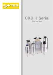
Besleme / Ölçme Girişleri
Düşük Gerilim Uyarı Işığı
Yüksek Gerilim Uyarı Işığı
Cihaz Işıklarının Anlamları
Yanıyor Yanmıyor Yanıp Sönüyor
Mevcut “U<” , “U>“ durumu
Kullanım ve Çalışma Prensibi
Ön paneldeki çalışma fonksiyonu ayarı ile cihazın koruma fonksiyonları seçilir ve
yüksek gerilim (Max.) ve düşük gerilim (Min.) ayarı kullanılarak, seçilen koruma
fonksiyonlarının üst ve alt çalışma gerilim sınırları belirlenir. Ayarlanan bırakma
) yüksek ve düşük gerilim için ortak kullanılır.
Çalışma fonksiyonu ayar seçenekleri;
W Düşük gerilim ve yüksek gerilim koruması
U + S Düşük gerilim ve faz sırası koruması
W + S Düşük gerilim, yüksek gerilim ve faz sırası koruması
Çalışma fonksiyonu olarak seçimi yapıldığında, alt ve üst W veya W+S
gerilim sınırlarına dikkat ederek ayar yapılmalıdır. Alt gerilim sınırı, üst
gerilim sınırından yüksek ayarlanmamalıdır.
a) Düşük Gerilim Koruması
Ölçülen gerilimlerden herhangi biri/birkaçı ayarlanan düşük gerilim (U
değerinin alna düşerse, “U˂” ışığı ayarlanan bırakma gecikmesi (t
yanıp söner. Bırakma gecikmesi (t
) süresi dolduğunda röle bırakır, “OUT” ışığı
söner ve “U˂” ışığı sürekli yanar.
GKRC-30F relay is delay-o and delay-on capable voltage monitoring relay which
has adjustable over and under voltage limits and selectable operang funcon.
It can be used in 1-phase and 3-phase air condioning systems, in electronic
command and control systems, for protecon of capacitors in PFC systems and
for protecon of equipment like motors.
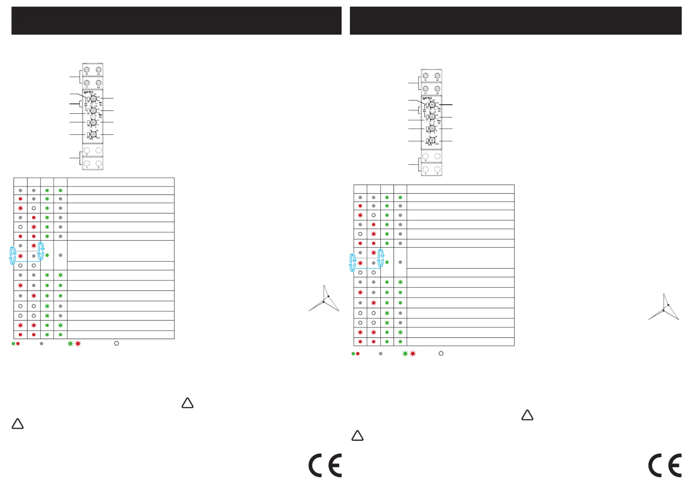
Supply / Measurement Inputs
Under Voltage Warning LED
Phase Sequence Warning LED
Ulisaon and Working Principle
The protecon funcons of the device are selected by the funcon adjustment
knob on the front panel and the over and under voltage limits of the selected
funcons are determined by using the over voltage (Max.) and under voltage (Min.)
adjustment knobs. Adjusted the delay-o (t
) me is used for both the adjusted
Funcon adjustment opons;
U Under voltage protecon
W Under voltage and over voltage protecon
U + S Under voltage and phase sequence protecon
W + S Under voltage, over voltage and phase sequence protecon
When W or W+S is selected as the operaon funcon,the adjusment must
be made taking into account the over and under voltage limits. The under
voltage limit must not be adjusted higher than the over voltage limit.
a)Under Voltage Monitoring
If one or many of the measured voltage values fall below the adjusted under
voltage limit (Umin), “U˂” LED ashes during the adjusted delay-o me (t
) expires, the relay output switches into OFF, “OUT”
Gerilimler ayarlanan sınırların içinde
Aşırı düşük gerilim uyarısı
Aşırı yüksek gerilim uyarısı
Yüksek ve düşük gerilim uyarısı
Faz sırası hatası (1sn.). (Sadece U+S ve W+S seçilirse)
Düşük veya yüksek gerilim mevcut durumu (1sn)
Röle çekme gecikme süresi (t
Röle bırakma gecikme süresi (t
) sayıyor (Düşük gerilim)
Röle bırakma gecikme süresi (t
) sayıyor (Yüksek gerilim)
Nötr kopma hatası (yavaş yavaş yanıp söner)
Yüksek ve düşük gerilim ayarları hatalı uyarısı
İlk açılışta ışık kontrolü
Voltages are within the adjusted limits
Extreme under voltage warning
Extreme over voltage warning
Both over and under voltage warning
Phase sequence fault (1sec.)
(Only if U+S and W+S are selected)
Over or under voltage present condion (1sec.)
Insucient supply voltage warning
Neutral break warning (ashing slowly)
Over and under voltage adjustments faulty warning
Light control at rst start-up