INSTALLATION INSTRUCTIONS FOR YOUR NEW
30" ELECTRIC SLIDE-IN RANGE
Before you begin - Read these instructions completely and carefully.
IMPORTANT - Save these instructions for local inspector’s use.
IMPORTANT - OBSERVE ALL GOVERNING CODES AND ORDINANCES.
Note to Installer - Be sure to leave these instructions with the Consumer.
Note to Consumer - Keep these instructions with your Use and Care Book for
future reference.
NOTE: This appliance must be properly grounded.
• All Ranges Can Tip
• Injury To Persons Could
Result
• Install Anti-tip Device Packed
With Range
• See Installation Instructions
WARNING
FOR YOUR SAFETY
1
CAUTION: For Personal
Safety remove house fuse or
open circuit breaker before
beginning installation. Failure
to do so could result in
serious injury or even death.
All rough-in and spacing dimensions must be
met for safe use of your range. Electricity to the
range can be disconnected at the outlet without
moving the range if the outlet is in the preferred
location (remove lower drawer).
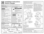
To reduce the risk of burns or re when reaching
over hot surface elements, cabinet storage
space above the cooktop should be avoided. If
cabinet storage space is to be provided above
the cooktop, the risk can be reduced by installing
a range hood that sticks out at least 5" beyond
the front of the cabinets. Cabinets installed
above a cooktop may be no deeper than 13".
Be sure your appliance is properly installed and
grounded by a qualied technician.
WARNING: To reduce the risk
of the thetipping appliance,
appliance must be secured by
properly installed anti-tip device
packed with the appliance.
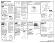
INSTALLATION OF THE
ANTI–TIP DEVICE
Before placing range in the counter, check the
factory location of the stability device on the
back of the range. For convenience you can
hook the stability chain in the upper set of
holes. Make sure there is no structural
interference when using the upper set of holes.
Remove all parts from the plastic bag found
inside the prepack of the oven and save
packaging tape.
STABILITY DEVICE
Fig. 1
INT303-6
Pub No. 31-10070