SP-15FX2
Soporte jo para televisores
Manual de instrucciones
Instruction manual
ES
EN
PT Manual de instruções
GRACIAS POR ESCOGER ESTE PRODUCTO GRUNKEL
GRUNKEL pone a su disposición productos innovadores, duraderos y prácticos. Bajo
un uso responsable y con el mantenimiento adecuado, le proporcionará una larga
vida útil y contribuirá a hacer del día a día una tarea mucho más sencilla.
Agradecemos su conanza y esperamos que disfrute de él.
Descubra el resto de nuestra gama en www.grunkel.com
Este manual es el reproducción en cuanto a características, funcionamiento y estética del producto que usted ha
adquirido salvo error tipográco, de imprenta o traducción. La especicación, funcionamiento y características de
este aparato están sujetos a cambios sin previo aviso.
Este manual é el reprodução em termos de características, operação e estética do produto que você adquiriu,
exceto erro tipográco, impressão ou tradução. A especicação, operação e características deste dispositivo estão
sujeitas a alterações sem aviso prévio.
This instruction manual is an accurate reproduction of the specications, operation and look of the product you
have just bought, except for typographical, print or translation errors. The specications, operation and features of
this product are subject to change without further notice.
• Por favor, lea detenidamente las instrucciones de uso de este
manual al completo antes de ponerlo en funcionamiento.
• Preste especial atención a las indicaciones de seguridad.
• Conserve este manual de instrucciones. Si cede el dispositivo a un
tercero, estas instrucciones también deben ser entregadas
• Guarde también la garantía, el ticket o factura de compra y, si es
posible, la caja con el embalaje interior para posibles solicitudes
en el futuro.
ANTES DE PONER EL PRODUCTO
EN FUNCIONAMIENTO
Tamaño de pantalla: 32” a 60”
Carga máxima: 60kg
VESA: 600mm x 400mm máx.
Perl: 2cm
Soporte de pared (x1)
Brazo de soporte (x2)
Manual de instrucciones (x1)
Kit de herramientas (x1)
Lea detenidamente estas instrucciones antes de comenzar. Si no está seguro de alguna
parte del proceso, contacte con un profesional o instalador para ayuda. Una instalación
inadecuada puede derivar en accidentes o lesiones.
La pared o la supercie donde vaya a instalarse el soporte debe soportar el peso combi-
nado del soporte y el televisor. En caso contrario, debe ser reforzada.
EspecicacionesContenido
Medidas de seguridad
LOS DATOS SOBRE CARGA MÁXIMA Y TAMAÑO MÁXIMO ADMITIDOS DE
ESTE SOPORTE DEPENDEN DE CADA MODELO DE TELEVISOR. LA VERACI-
DAD Y SEGURIDAD DE LOS DATOS PROPORCIONADOS POR CADA TELEVI-
SOR SON RESPONSABILIDAD DE SUS RESPECTIVOS FABRICANTES, Y NO
ESTÁN VINCULADAS A LAS ESPECIFICACIONES DE ESTE SOPORTE.
¡ATENCIÓN!
Localice tuberías, cables o cualquier otro peligro en la pared donde desee instalar el
soporte antes de taladrar.
Debe utilizarse equipamiento de seguridad y herramientas apropiadas. En caso contra-
rio podrían producirse accidentes o lesiones.
Se recomienda que la instalación sea llevada a cabo por dos personas. No intente le-
vantar una pantalla pesada sin ayuda.
Siga las instrucciones y recomendaciones referentes a la ventilación adecuada y ubi-
caciones apropiadas para montar su televisor. Consulte el manual de usuario de su
televisor particular para obtener más información.
PRECAUCIÓN: Este soporte ha sido diseñado para uso solo con un peso máximo de
60kg. Su uso con peso superior al indicado puede resultar en inestabilidad causando
posibles lesiones.
Destornillador
Llave inglesa (trinquete de 13mm (1/2”))
Taladro eléctrico o portátil
Broca de 6mm (1/4”) para instalación en pared de yeso o escayola
Broca de 10mm (3/8”) para instalación en pared de hormigón
(A) Tirafondo M8 x 63 (x4)
(F) Tornillo M8 x 12 (x4)
(B) Arandela de tirafondo (x4)
(G) Tornillo M8 x 30 (x4)
(C) Espiches (x4)
(H) Arandela M6 (x4)
(I) Arandela M8 (x4)
(J) Espaciador (x8)
(K) Llave Allen S4 (x1)
(D) Tornillo M6 x 12 (x4)
(E) Tornillo M6 x 30 (x4)
Parte 1A – Montaje en pared (yeso o escayola)
¡IMPORTANTE! Por motivos de seguridad, este soporte debe asegurarse con al menos
dos vigas de madera capaces de soportar el peso combinado del soporte y la pantalla.
Herramientas requeridas
Material
Instalación
Escoja una pared lisa y con suciente grosor. Use un localizador de vigas para localizar
dos vigas adyacentes donde desee instalar su soporte. Marque los dos bordes de am-
bas vigas para identicar el centro exacto.
NOTA: Debe usar el centro de cada viga para evitar agrietamiento o rotura de la madera
durante la instalación.
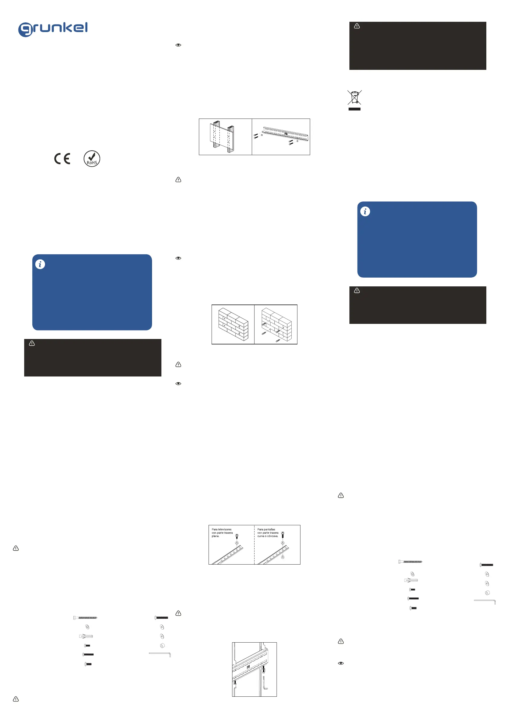
Coloque la parte posterior del soporte contra la pared. Asegúrese de que esté nivelada.
Con la ayuda de otra persona haga 4 marcas (dos a la derecha y dos a la izquierda) en
el centro del soporte para asegurar el soporte a la pared (ver. Fig. 1).
Perforar 6 mm (1/8 “) las cuatro marcas realizadas como guía.
Coloque el soporte contra la pared y asegúrelo utilizando los tornillos (A) y las aran-
delas (lag bolt) (B) (véase gura. 2). No apriete demasiado las arandelas y no suelte
el soporte hasta asegurarse de que está en su sitio. Asegúrese de que el soporte esté
nivelado antes de apretar las arandelas
Parte 1B – Montaje sobre pared (hormigón)
¡IMPORTANTE! Por motivos de seguridad, el muro debe ser capaz de soportar el peso
combinado del soporte y la pantalla. El fabricante no asume responsabilidad por fallo
producido por muros de fuerza insuciente.
Coloque la parte posterior del soporte contra la pared. Asegúrese de que esté nivelada.
Mientras otra persona sujeta el soporte contra la pared, haga cuatro marcas (dos en la
derecha y una en la izquierda) para asegurar el soporte en la pared (ver g. 3).
Perforar un agujero de 10 mm (3/8 “) en cada punto marcado. Retire cualquier exceso
de polvo de los agujeros.
Inserte un espiche (C) en cada agujero para que esté al mismo nivel con la supercie
de hormigón (ver. Fig. 4). Se puede utilizar un martillo para jar ligeramente los anclajes
en su lugar si es necesario.
Fig.1
Fig.2
NOTA: si el muro está cubierto por una capa de yeso, el espiche debe pasar comple-
tamente a través de la capa para permanecer a ras con la supercie del hormigón.
Coloque el soporte contra la pared y conéctelo utilizando los tornillos (A) las arandelas
(lag volts) (B) (ver g 2). No apriete demasiado las arandelas y no suelte el soporte
hasta asegurarse de que está en su sitio. Asegúrese de que el soporte esté nivelado
antes de apretar las arandelas.
No apriete demasiado los tornillos. Asegúrese de que el soporte esté nivelado antes
de apretar los tornillos.
Parte 2 – Ensamblar el soporte al televisor
¡IMPORTANTE! Tenga especial cuidado durante esta parte de la instalación. Si es posi-
ble, evite colocar su pantalla hacia abajo p1-ya que podría dañar la supercie.
NOTA: este soporte incluye una selección de tornillos de diferentes diámetros y longi-
tudes para ajustarse a una amplia variedad de modelos de televisor. No todo el mate-
rial en el kit será usado. Si no puede encontrar el tornillo del tamaño adecuado en el kit,
consulte a su proveedor para obtener más información.
Determine correctamente la longitud del tornillo que va a utilizar, examinando de nuevo
la parte trasera de su pantalla:
- Si la parte trasera de su pantalla es plana y los agujeros del soporte están a ras de la
supercie, deberá utilizar los tornillos cortos (D o F) del kit de accesorios.
- Si la parte trasera de su pantalla es curva o los agujeros del soporte están huecos,
deberá utilizar los tornillos largos (E o G) y probablemente, necesitará también utilizar
los separadores (J).
Determinar el diámetro correcto del tornillo a utilizar. Aconsejamos que cuidadosamen-
te pruebe uno de cada tamaño (M6 y M8) del kit de accesorios. No fuerce los tornillos
- si siente resistencia, cambie este tornillo por uno más pequeño, pero no lo fuerce.
Fig.3 Fig.4
Parte 3 – Ensamblaje nal
Con la ayuda de otra persona, coloque su pantalla sobre el soporte. No suelte la panta-
lla hasta que el soporte esté totalmente asegurado.
Apriete los tornillos para más seguridad con la llave Allen (K) (ver g. 6) para evitar que
la pantalla se caiga de la pared de soporte.
¡IMPORTANTE! Estos tornillos deben de ser apretados al máximo para evitar la caída
accidental de la pantalla.
Limpie periódicamente su montura con un paño seco. Inspeccione todos los tornillos
y juntas de forma regular para garantizar que ninguna conexión se ha aojado con el
paso del tiempo.
Fije el soporte a la pantalla con los tornillos identicados en el paso 1 y 2 (ver gura 5):
- Si está utilizando los tornillos M6, necesitará utilizar las arandelas M6 (H). Si está
utilizando los M8, necesitará utilizar las arandelas M8. (I)
- Si está utilizando los tonillos largos o la pantalla por detrás está curva o hueca, necesi-
tará utilizará los espaciadores Utilice los espaciadores sólo si es necesario. (J)
Fig.5
Fig.6
LOS NIÑOS MENORES DE 8 AÑOS NO DEBEN UTILIZAR NI LIMPIAR ESTE
APARATO SIN LA SUPERVISIÓN DE UN ADULTO. TAMPOCO PUEDE SER
UTILIZADO NI LIMPIADO POR PERSONAS CON CAPACIDADES FÍSICAS,
MENTALES O SENSORIALES REDUCIDAS, SIN EXPERIENCIA O CONOCI-
MIENTO DEL USO DEL MISMO, O QUE NO HAYAN RECIBIDO LA FORMA-
CIÓN ADECUADA BAJO LA SUPERVISIÓN DIRECTA DE UNA PERSONA
CAPACITADA.
¡ATENCIÓN!
Normas sobre los residuos de los aparatos eléctricos según la DIRECTI-
VA RAEE 2002/96/EC. Este símbolo signica que el presente producto no
puede ser tratado como residuos domésticos normales, sino que debe ser
devuelto al distribuidor, o entregarse en el correspondiente punto de reco-
gida de equipos eléctricos o electrónicos, o llevarlo a un punto de recogida
habilitado a tal n con objeto de que sus componentes sean reciclados y no se mezclen
con la basura doméstica.
También puede avisar al servicio de recogida de su municipio para que sea recogido y
tratado de la forma correspondiente, siguiendo las instrucciones de protección al me-
dio ambiente o para que le aconsejen como hacerlo.
La eliminación de un electrodoméstico signica evitar posibles consecuencias nega-
tivas para el medio ambiente y la salud. Una eliminación adecuada permite obtener
un ahorro importante de energía y recursos. Como un recordatorio de la necesidad de
eliminar por separado los electrodomésticos, en el producto aparece un cubo de basura
con ruedas tachado
Eliminación de la unidad
ENG - Instruction manual
• Please, read carefully the entire instruction manual before using it.
• Pay special attention to the safety indications.
• Keep this instruction manual. If you hand over this applicance to
another person, these instructions must be also be transferred.
• Keep also the guarantee card, purchase ticket or invoice. If
possible, keep the original box with all the accessories included for
future inquiries.
BEFORE PUTTING THE APPLIANCE
INTO OPERATION
Display Size: 32” to 60”
Maximum Load: 60kg
Mounting Pattern: 600 x 400mm
Prole: 2cm
Wall plate (x1)
Mount arm (x2)
Instruction manual (x1)
Hardware kit (x1)
Read these instructions before you begin. If you are unsure of any part of the process,
contact a professional contractor or installer for assistance. Improper installation can
result in injury or damage.
The wall or mounting surface must be capable of supporting the combined weight of
the mount and the display; if not, the structure must be reinforced.
SpecicationsContent
General safety instructions
WARNING!
THE INFORMATION RELATED TO MAXIMUM LOAD AND MAXIMUM SIZE
SUPPORTED BY THIS MOUNT DEPEND ON EACH TV MODEL INDIVIDUALLY.
THE TRUTHFULNESS AND SAFETY OF THE PROVIDED INFORMATION ARE
THE SOLE RESPONSIBILITY OF THEIR RESPECTIVE MANUFACTURERS,
AND ARE NOT ASSOCIATED WITH THIS PRODUCT IN ANY WAY.
Locate pipes, wires, or any other hazards in the wall where you wish to install the mount
before drilling.
Safety gear and proper tools must be used. Failure to do so can result in injury or da-
mage.
Two people are recommended for installation. Do not attempt to lift a heavy display
without assistance.
Follow all instructions and recommendations regarding adequate ventilation and suita-
ble locations for mounting your display. Consult the owner‘s manual for your particular
display for more information.
CAUTION: This wall mount is intended for use only with the maximum weight of 60kg
(130 lbs). Use with heavier than the maximum weights indicated may result in instabi-
lity causing possible injury.
Phillips Head Screw Driver
Ratchet or Driver with 13 mm (1/2”) Socket
Electric or Portable Drill
6 mm (1/4”) Drill Bit and Stud Finder for Drywall Installation
10 mm (3/8”) Masonry Bit for Concrete Installation
Tools required
A) M8 x 63 Screw (x4)
(F) M8 x 12 Screw (x4)
(B) Lag Bolt Washer (x4)
(G) M8 x 30 Screw (x4)
(C) Concrete Anchor
(H) M6 Washer (x4)
(I) M8 Washer (x4)
(J) Spacer (x8)
(K) S4 Allen Key (x1)
(D) M6 x 12 Screw (x4)
(E) M6 x 30 Screw (x4)
Part 1A – Mounting to the Wall (Drywall)
IMPORTANT! For safety reasons, this mount must be secured to at least two wood
studs no less than 16” apart. The studs must be capable of supporting the combined
weight of the mount and the display.
Hardware kit
Installation
NOTE: If the concrete wall is covered by a layer of plaster or drywall, the concrete
anchor must pass completely through the layer to rest ush with the concrete surface.
Place the wall plate back against the wall and attach it using the lag bolts (A) and lag
bolt washers (B) provided (see Fig. 2). Do not over-tighten these bolts and do not relea-
se the wall plate until all bolts are in place. Ensure that the wall plate remains level after
all bolts are secured.