Hasselblad HTS 1.5 Manual
Hasselblad
Ikke kategoriseret
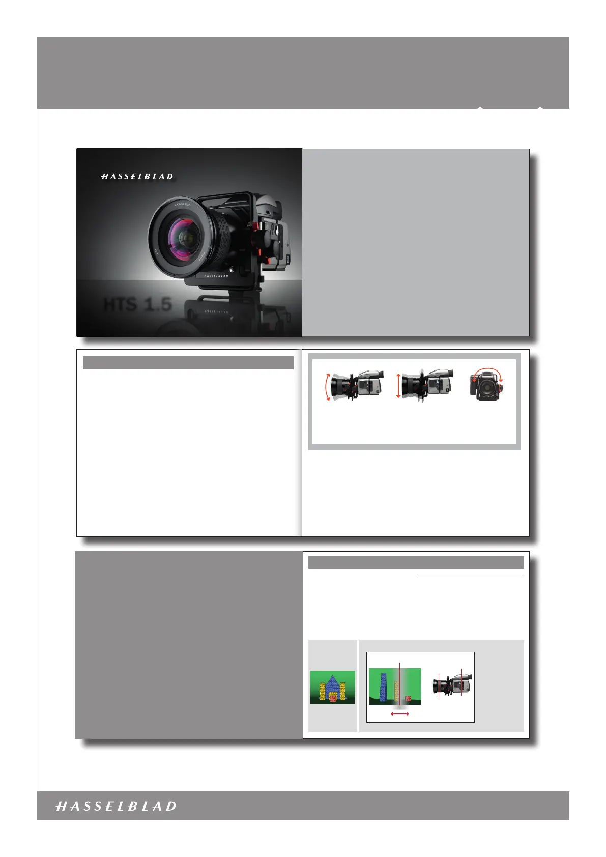
HTS 1.5
| Mærke: | Hasselblad |
| Kategori: | Ikke kategoriseret |
| Model: | HTS 1.5 |
Har du brug for hjælp?
Hvis du har brug for hjælp til Hasselblad HTS 1.5 stil et spørgsmål nedenfor, og andre brugere vil svare dig
Ikke kategoriseret Hasselblad Manualer

15 Juli 2025
7 Juli 2025
7 Juli 2025
7 Juli 2025

7 Juli 2025
7 Juli 2025
7 Juli 2025
7 Juli 2025
7 Juli 2025
7 Juli 2025
Ikke kategoriseret Manualer
- Liam&Daan
- Backscatter
- Turbo Air
- Belena
- Bellini
- Lenz
- DK2 Power
- Life Finds
- Qubino
- BlueWalker
- Peugeot
- Overtone Labs
- NANO Modules
- Gentex
- Yuede
Nyeste Ikke kategoriseret Manualer

23 December 2025

22 December 2025

22 December 2025

22 December 2025

22 December 2025

22 December 2025

21 December 2025

21 December 2025

21 December 2025

21 December 2025