Hikvision DS-PDC10DM-VG3 Manual
Hikvision
Alarmsystem
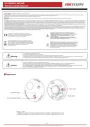
DS-PDC10DM-VG3

| Mærke: | Hikvision |
| Kategori: | Alarmsystem |
| Model: | DS-PDC10DM-VG3 |
Har du brug for hjælp?
Hvis du har brug for hjælp til Hikvision DS-PDC10DM-VG3 stil et spørgsmål nedenfor, og andre brugere vil svare dig
Alarmsystem Hikvision Manualer
30 September 2025
28 Juli 2025
27 Juli 2025
27 Juli 2025
27 Juli 2025
6 Juli 2025
6 Juli 2025
6 Juli 2025

18 December 2024

2 September 2024
Alarmsystem Manualer
- X4-Tech
- Bosch
- Steren
- DSC
- Tzumi
- Electia
- Yale
- Pentatech
- Atlantis Land
- Dahua Technology
- Steinel
- Honeywell
- ConiuGo
- Hager
- Xavax
Nyeste Alarmsystem Manualer

15 December 2025

11 December 2025

10 December 2025

1 December 2025

30 November 2025

30 November 2025

29 November 2025

29 November 2025

28 November 2025

26 November 2025