Wired PIR Ceiling Detector
DS-PDCL12-EG2
User Manual
EN 50131-1: 2006+A1+A2+A3
EN 50131-2-2: 2017
Environment Class II
Security Grade2
Tested by TÜV Rheinland
Hangzhou Hikvision Digital Technology CO.,Ltd. No.555 Qianmo Road, Binjiang District, Hangzhou 310052, China
English
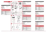
Appearance
Specification
5
6
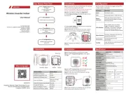
Resistor Wiring
Connection Type
Detection Range
Powering On
Note: The resistor must be connected in series with one end of the
detector.
a. Normally Closed
b. Single End of Line Wiring
c. Double End of Line Wiring
After powering on, the indicator flashes rapidly. Once the detector self test is
completed, the LED indicator will go out until the detector detects movement.
Relay Status
Normal PIR Alarm PIR Fault Tamper
Alarm Relay Close Open Open Close
Tamper Relay Close Close Close Open
Mounting by Expansion Screw
Reinforcing Buckle by Screw (Optional)
a
b
UD23903B-E
Please use the power supplies comply with the requirements of EN 50131-6 at
the appropriate grade and environmental class.
Please do not obscure the detector’s field of view partially or completely.
Installation
1. Tamper EOL pin 2. Terminals 3. Alarm EOL pin
4. LED jumper 5. Sensitivity jumper 6. PIR sensor
7. Tamper 8. LED indicator
Method 1: Use the jumper to select EOL (End of Line) resistance on
TAMPER/ALARM EOL pins.
Method 2: Add the resistor to TAMPER/ALARM wiring ports.
Note: If EOL wiring is not used, leave the jumpers OFF. Do not force the
jumper if it is not matched the pin. Method 1 & 2 should not be used on the
ALARM/TAMPER at the same time.
a. Alarm Resistance: 1K, 2K2, 4K7, 5K6, 6K8
b. Tamper Resistance: 1K, 2K2, 4K7, 5K6
Detection method Passive Infrared
Detection range 12 m
Detection Angle 360°
Detection zones 172
Detectable speed 0.3~2 m/s
Sensitivity Auto, low
White light filter 6500lux
Digital temperature compensation Support
Creep zone protection Support
Digital processing Support
Sealed optics Support
Tamper protection Front
LED indicator Blue (Alarm)
Power supply 9 to 16 VDC
Typical voltage 12 VDC
Operation temperature -10 °C to 55 °C (14 °F to 131 °F)
Storage temperature -20 °C to 60 °C (-4 °F to 140 °F)
Operation humidity 10% to 90%
Dimension φ101.2 mm × 32.9 mm
Weight 109.5 g
Mounting height 2.4 to 4 m
Mounting method Ceiling
Application scenario Indoor
Power Consumption 13mA Max
2
1
1 2
a
2_KA3×25
a
=
=
4K7
2K2
1K
5K6
ALARM +
-
EOL
TAMPER
EOL
2.2K
4K7
2K2
1K
5K6
6K8
ALARM +
-
EOL
TAMPER
EOL
2.2K
b
ALARM
TAMPER
b
12
3
3
5
ZONE2
COM
ZONE1
COM
+-
ALARMTAMPER +-
6K8
5K6
4K7
2K2
1K
5K6
4K7
2K2
1K
ALARMTAMPER
EOLEOL
a
2.2K 2.2K
4
ZONE2
COM
ZONE1
COM
+-
ALARMTAMPER +-
6K8
5K6
4K7
2K2
1K
5K6
4K7
2K2
1K
ALARMTAMPER
EOLEOL
b
ZONE2
COM
ZONE1
COM
+-
ALARMTAMPER +-
6K8
5K6
4K7
2K2
1K
5K6
4K7
2K2
1K
ALARMTAMPER
EOLEOL
c
8
7
6
1
45
101.2 mm
101.2 mm
32.9 mm
8m
10m
12m
2.4m 3m 4m
4m
2m
0m
6m
2m
4m
6m
6m 6m4m 4m2m 2m0m
Zone:172 Plane:3
1K,2K2,
4K7,5K6
1K, 2K2,
4K7, 5K6, 6K8
LED ON
LOW
LED OFF
AUTO (Default)
2
3