Wireless Receiver
DS-PM1-RT-HWB
User Manual
Hangzhou Hikvision Digital Technology CO.,Ltd. No.555 Qianmo Road, Binjiang District, Hangzhou 310052, China
UD28060B
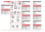
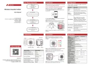
Appearance
Installation
Wiring
Address Settings
1
2
3
4
English
1. Indicator
2. Tamper Button 3. Wiring Terminal 4. DIP Switch
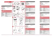
Specification
1
2
3 4
2
3
4
2
1
1 2
BUS
D-
Speed-X BUS
CONTROL
PANEL
CONTROL
PANEL
WIRELESS
RECEIVER
EXPANDER
WIRELESS
RECEIVER
EXPANDER
DC
POWER
BUS_IN BUS_IN
D+ - +
DC_IN
Lowbit Highbit
BIN=000011 Address=3
Configure the address via DIP switch of the receiver before
powering on the system. The address should be in the range (0
to 63). The address of each receiver should be unique.
The binary value shown in the diagram is 000011, which means
the decimal value is 3, so the address of the module is 3.
Flashing green:
Find me mode
Solid green: Enrolled Solid orange:
Enrolling failed/Fault (Disconnected)
Quickly flashing orange:
Alarm
Green and orange quickly
flashing alternately:
Enrolling
FCC Information
Please take attention that changes or modification not
expressly approved by the party responsible for compliance
could void the user’s authority to operate the equipment.
FCC compliance: This equipment has been tested and found
to comply with the limits for a Class B digital device, pursuant
to part 15 of the FCC Rules. These limits are designed to
provide reasonable protection against harmful interference
in a residential installation. This equipment generates, uses
and can radiate radio frequency energy and, if not installed
and used in accordance with the instructions, may cause
harmful interference to radio communications. However,
there is no guarantee that interference will not occur in a
particular installation. If this equipment does cause harmful
interference to radio or television reception, which can be
determined by turning the equipment off and on, the user is
encouraged to try to correct the interference by one or more
of the following measures:
—Reorient or relocate the receiving antenna.
—Increase the separation between the equipment and
receiver.
—Connect the equipment into an outlet on a circuit different
from that to which the receiver is connected.
—Consult the dealer or an experienced radio/TV technician
for help.
This equipment should be installed and operated with a
minimum distance 20cm between the radiator and your
body.
FCC Conditions
This device complies with part 15 of the FCC Rules. Operation
is subject to the following two conditions:
1. This device may not cause harmful interference.
2. This device must accept any interference received,
including interference that may cause undesired operation
D D
BUS12VD C_IN
ON
ON
ON
ONON
BUS_ADDR
BUS_ADDR
BUS_ADDR
BUS_ADDRBUS_ADDR
DIP
DIP
DIP
DIPDIP
6
6
6
66
D D
BUS12VD C_IN
ON
ON
ON
ONON
BUS_ADDR
BUS_ADDR
BUS_ADDR
BUS_ADDRBUS_ADDR
DIP
DIP
DIP
DIPDIP
6
6
6
66
©2022 Hangzhou Hikvision Digital Technology Co., Ltd. All rights reserved.
About this Manual
The Manual includes instructions for using and managing the Product. Pictures, charts, images and all other
information hereinafter are for description and explanation only. The information contained in the Manual
is subject to change, without notice, due to firmware updates or other reasons. Please find the latest
version of this Manual at the Hikvision website (https://www.hikvision.com/).
Please use this Manual with the guidance and assistance of professionals trained in supporting the Product.
and other Hikvision’s trademarks and logos are the properties of Hikvision in various jurisdictions.
Other trademarks and logos mentioned are the properties of their respective owners.
Disclaimer
TO THE MAXIMUM EXTENT PERMITTED BY APPLICABLE LAW, THIS MANUAL AND THE PRODUCT DESCRIBED,
WITH ITS HARDWARE, SOFTWARE AND FIRMWARE, ARE PROVIDED “AS IS” AND “WITH ALL FAULTS AND
ERRORS”. HIKVISION MAKES NO WARRANTIES, EXPRESS OR IMPLIED, INCLUDING WITHOUT LIMITATION,
MERCHANTABILITY, SATISFACTORY QUALITY, OR FITNESS FOR A PARTICULAR PURPOSE. THE USE OF THE
PRODUCT BY YOU IS AT YOUR OWN RISK. IN NO EVENT WILL HIKVISION BE LIABLE TO YOU FOR ANY
SPECIAL, CO NSEQUENTIAL, INCIDENTAL, OR INDIRECT DAMAGES, INCLUDING, AMONG OTHERS, DAMAGES
FOR LOSS OF BUSINESS PROFITS, BUSINESS INTERRUPTION, OR LOSS OF DATA, CORRUPTION OF SYSTEMS,
OR LOSS OF DOCUMENTATION, WHETHER BASED ON BREACH OF CONTRACT, TORT (INCLUDING
NEGLIGENCE), PRODUCT LIABILITY, OR OTHERWISE, IN CONNECTION WITH THE USE OF THE PRODUCT, EVEN
IF HIKVISION HAS BEEN ADVISED OF THE POSSIBILITY OF SUCH DAMAGES OR LOSS.
YOU ACKNOWLEDGE THAT THE NATURE OF THE INTERNET PROVIDES FOR INHERENT SECURITY RISKS, AND
HIKVISION S HALL NOT TAKE ANY RESPONSIBILITIES FOR ABNORMAL OPERATION, PRIVACY LEAKAGE OR
OTHER DAMAGES RESULTING FROM CYBER-ATTACK, HACKER ATTACK, VIRUS INFECTION, OR OTHER
INTERNET SECURITY RIS KS; HOWEVER, HIKVISION WILL PROVIDE TIMELY TECHNICAL SUPPORT IF REQUIRED.
YOU AGREE TO USE THIS PRODUCT IN COMPLIANCE WITH ALL APPLICABLE LAWS, AND YOU ARE SOLELY
RESPONSIBLE FOR ENSURING THAT YOUR USE CONFORMS TO THE APPLICABLE LAW. ESPECIALLY, YOU ARE
RESPONSIBLE, FOR USING THIS PRODUCT IN A MANNER THAT DOES NOT INFRINGE ON THE RIGHTS OF
THIRD PARTIES, INCLUDING WITHOUT LIMITATION, RIGHTS OF PUBLICITY, INTELLECTUAL PROPERTY RIGHTS,
OR DATA PROTECTION AND OTHER PRIVACY RIGHTS. YOU SHALL NOT USE THIS PRODUCT FOR ANY
PROHIBITED END-USES, INCLUDING THE DEVELOPMENT OR PRODUCTION OF WEAPONS OF MASS
DESTRUCTION, THE DEVELOPMENT OR PRODUCTION OF CHEMICAL OR BIOLOGICAL WEAPONS, ANY
ACTIVITIES IN THE CONTEXT RELATED TO ANY NUCLEAR EXPLOSIVE OR UNSAFE NUCLEAR FUEL-CYCLE, OR IN
SUPPORT OF HUMAN RIGHTS ABUSES.
IN THE EVENT OF ANY CONFLICTS BETWEEN THIS MANUAL AND THE APPLICABLE LAW, THE LATER PREVAILS.
This product and - if applicable - the supplied accessories too are marked with "CE" and comply
therefore with the applicable harmonized European standards listed under the Directive
2014/53/EU(RED),Directive 2014/30/EU(EMCD),Directive 2014/35/EU(LVD),Directive 2011/65/
EU(RoHS).
2012/19/EU (WEEE directive): Products marked with this symbol cannot be disposed of as
unsorted municipal waste in the European Union. For proper recycling, return this product to
your local supplier upon the purchase of equivalent new equipment, or dispose of it at
designated collection points. For more information see: www.recyclethis.info
2006/66/EC (battery directive): This product contains a battery that cannot be disposed of as
unsorted municipal waste in the European Union. See the product documentation for specific
battery information. The battery is marked with this symbol, which may include lettering to
indicate cadmium (Cd), lead (Pb), or mercury (Hg). For proper recycling, return the battery to
your supplier or to a designated collection point. For more information see: www.recyclethis.info
ELECTRIC CAUTION
- In the use of the product, you must be in strict compliance with the electrical
safety regulations of the nation and region.
- Shock hazard! Disconnect all power sources before maintenance.
- The socket-outlet shall be installed near the equipment and shall be easily
accessible.
- Ensure correct wiring of the terminals for connection to an AC mains supply.
- The equipment has been designed, when required, modified for connection to an
IT power distribution system.
BATTERY CAUTION
1. This equipment is not suitable for use in locations where children are likely to be
present.
2. CAUTION: Risk of explosion if the battery is replaced by an incorrect type.
3. Improper replacement of the battery with an incorrect type may defeat a
safeguard (for example, in the case of some lithium battery types).
4. Do not dispose of the battery into fire or a hot oven, or mechanically crush or
cut the battery, which may result in an explosion.
5. Do not leave the battery in an extremely high temperature surrounding
environment, which may result in an explosion or the leakage of flammable liquid
or gas.
6. Do not subject the battery to extremely low air pressure, which may result in an
explosion or the leakage of flammable liquid or gas.
7. Dispose of used batteries according to the instructions.
1. Risk of explosion if the battery is replaced by an incorrect type.
2. Improper replacement of the battery with an incorrect type may defeat a
safeguard (for example, in the case of some lithium battery types).
3. Do not dispose of the battery into fire or a hot oven, or mechanically crush or
cut the battery, which may result in an explosion.
4. Do not leave the battery in an extremely high temperature surrounding
environment, which may result in an explosion or the leakage of flammable liquid
or gas.
5. Do not subject the battery to extremely low air pressure, which may result in an
explosion or the leakage of flammable liquid or gas.
6. Dispose of used batteries according to the instructions.
+ identifies the positive terminal(s) of equipment which is used with, or generates
direct current. + identifies the negative terminal(s) of equipment which is used with,
or generates direct current.
FIRE CAUTION
- This equipment is suitable for mounting on concrete or other non-combustible
surface only.
- The serial port of the equipment is used for debugging only.
INSTALLATION CAUTION
- This equipment is not suitable for use in locations where children are likely to be
present.
- Keep the equipment vertically down when moving or using it.
1. Install the equipment according to the instructions in this manual.
2. To prevent injury, this equipment must be securely attached to the floor/wall in
accordance with the installation instructions.
BIN Address BIN Address
000001 1
000000 0 111000 56
000010 2
111001 57
000011 3
111010 58
000100 4
111011 59
000101 5
111100 60
000110 6
111101 61
000111 7
111110 62
111111 63
Slowly flashing light green:
Waiting for enrollment
Bus 1 Speed-X bus
Power supply 9 to 28 VDC, 1 A
Power consumption Maximum current 100 mA@12 VDC;
Quiescent current 40 mA@12 VDC
RF frequency 433 MHz
Wireless security Frequency Hoping 128 AES
Encryption
Dimension(W × H × D) 110 mm × 155 mm × 32 mm
Shell material Plastic
Weight 233 g
Operation temperature -10 °C to 40 °C
Operation humidity 10% to 90%
Alarm input Up to 32 wireless detectors (portable
emergency button is not included)
Wireless sounder Up to 4 wireless indoor sounder, 8
wireless outdoor sounder
Green: Power/Find me
Orange: Alarm/Fault
LED Indicator
1 Indicator
2 Tamper Button
3 Wiring Terminal
4 DIP Switch