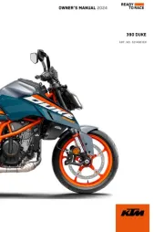
KTM 390 Duke (2018) Manual

KTM Motorcykel 390 Duke (2018)

Læs nedenfor 📖 manual på dansk for KTM 390 Duke (2018) (261 sider) i kategorien Motorcykel. Denne guide var nyttig for 38 personer og blev bedømt med 4.9 stjerner i gennemsnit af 19.5 brugere

Side 1/261
OWNER'S MANUAL 2018
390 Duke
Art. no. 3213783en
DEAR KTM CUSTOMER
*3213783en*
3213783en
01/2018
DEAR
DEAR
DEAR
DEARDEAR KTM
KTM
KTM
KTMKTM CUSTOMER
CUSTOMER
CUSTOMER
CUSTOMERCUSTOMER
Congratulations on your decision to purchase a KTM motorcycle. You are now the owner of a state-of-the-art
sports motorcycle that will give you enormous pleasure if you service and maintain it properly.
We hope you enjoy riding this motorcycle!
Enter the serial numbers of your vehicle below.
Chassis number ( p. 32) Dealer's stamp
Engine number ( p. 33)
Key number ( p. 34)
The Owner's Manual contained the latest information for this model series at the time of going to print. However,
minor differences due to further developments in design cannot be ruled out completely.
All specifications are non-binding. KTM Sportmotorcycle GmbH specifically reserves the right to modify or delete
technical specifications, prices, colors, forms, materials, services, designs, equipment, etc., without prior notice
and without specifying reasons, to adapt these to local conditions, as well as to stop production of a particular
model without prior notice. KTM accepts no liability for delivery options, deviations from figures and descriptions,
misprints, and other errors. The models portrayed partly contain special equipment that does not belong to the
regular scope of supply.
© 2018 KTM Sportmotorcycle GmbH, Mattighofen Austria
All rights reserved
DEAR KTM CUSTOMER
2
Reproduction, even in part, as well as copying of all kinds, is permitted only with the express written permission
of the copyright owner.
ISO 9001(12 100 6061)
According to the international quality management standard ISO 9001, KTM uses quality assur-
ance processes that lead to the maximum possible quality of the products.
Issued by: TÜV Management Service
KTM Sportmotorcycle GmbH
Stallhofnerstraße 3
5230 Mattighofen, Austria
This document is valid for the following models:
390 Duke US (F4375R1, F4375R2)
TABLE OF CONTENTS
3
TABLE
TABLE
TABLE
TABLETABLE OF
OF
OF
OFOF CONTE NTS
CONTENTS
CONTENTS
CONTENTSCONTENTS
1 MEANS OF REPRESENTATION ...................... 9
1.1 Symbols used .................................... 9
1.2 Formats used................................... 10
2 SAFETY ADVICE.......................................... 11
2.1 Use definition.................................. 11
2.2 Misuse............................................ 11
2.3 Safety advice................................... 11
2.4 Degrees of risk and symbols .............. 12
2.5 Overview of labels ............................ 14
2.6 Consumer rights............................... 18
2.7 Operating noise warning ................... 18
2.8 Noise emission warranty ................... 18
2.9 Reporting safety defects ................... 19
2.10 Tampering warning........................... 19
2.11 Safe operation ................................. 20
2.12 Protective clothing ........................... 21
2.13 Work rules....................................... 22
2.14 Environment.................................... 22
2.15 Owner's Manual ............................... 23
3 IMPORTANT NOTES.................................... 24
3.1 Manufacturer and implied warranty.... 24
3.2 Operating and auxiliary substances .... 24
3.3 Spare parts, accessories ................... 24
3.4 Service ........................................... 25
3.5 Figures ........................................... 25
3.6 Customer service.............................. 25
4 VIEW OF VEHICLE ...................................... 28
4.1 View of vehicle, front left (example) ... 28
4.2 View of vehicle, rear right
(example)........................................ 30
5 SERIAL NUMBERS ..................................... 32
5.1 Chassis number ............................... 32
5.2 Type label ....................................... 32
5.3 Engine number ................................ 33
5.4 Key number..................................... 34
6 CONTROLS................................................. 35
6.1 Clutch lever..................................... 35
6.2 Hand brake lever.............................. 35
6.3 Throttle grip .................................... 36
6.4 Switches on the left side of the
handlebar........................................ 36
6.4.1 Combination switch...................... 36
6.4.2 Light switch ................................ 37
6.4.3 Menu switch................................ 38
6.4.4 Turn signal switch........................ 38
6.4.5 Horn button ................................ 39
TABLE OF CONTENTS
8
25 AUXILIARY SUBSTANCES ......................... 247
26 STANDARDS ............................................ 249
27 INDEX OF SPECIAL TERMS ....................... 250
28 LIST OF ABBREVIATIONS.......................... 251
29 LIST OF SYMBOLS.................................... 252
29.1 Red symbols.................................. 252
29.2 Yellow and orange symbols.............. 252
29.3 Green and blue symbols.................. 252
INDEX ............................................................. 254
MEANS OF REPRESENTATION 1
9
1.1 Symbols used
The meaning of specific symbols is described below.
Indicates an expected reaction (e.g. of a work step or a function).
Indicates an unexpected reaction (e.g. of a work step or a function).
All work marked with this symbol requires specialist knowledge and technical understanding.
In the interest of your own safety, have these jobs performed by an authorized KTM workshop!
Your motorcycle will be optimally cared for there by specially trained experts using the auxiliary
tools required.
Indicates a page reference (more information is provided on the specified page).
Indicates information with more details or tips.
Indicates the result of a testing step.
1 MEANS OF REPRESENTATION
10
Indicates a voltage measurement.
Indicates a current measurement.
Indicates the end of an activity, including potential rework.
1.2 Formats used
The typographical formats used in this document are explained below.
Proprietary name Indicates a proprietary name.
Name®Indicates a protected name.
Brand™ Indicates a brand available on the open market.
Underlined terms Refer to technical details of the vehicle or indicate technical terms, which
are explained in the glossary.
SAFETY ADVICE 2
11
2.1 Use definition
KTM sport motorcycles are designed and constructed to meet the normal demands of regular road operation but
not for use on race courses or offroad.
Info
The motorcycle is authorized for public road traffic in the homologous version only.
2.2 Misuse
The vehicle must only be used as intended.
Dangers can arise for people, property and the environment through use not as intended.
Any use of the vehicle beyond the intended and defined use constitutes misuse.
Misuse also includes the use of operating and auxiliary fluids which do not meet the required specification for the
respective use.
2.3 Safety advice
A number of safety instructions need to be followed to operate the product described safely. Therefore read this
instruction and all further instructions included carefully. The safety instructions are highlighted in the text and
are referred to at the relevant passages.
2 SAFETY ADVICE
12
Info
Various information and warning labels are attached in prominent locations on the product described. Do
not remove any information or warning labels. If they are missing, you or others may not recognize dangers
and may therefore be injured.
2.4 Degrees of risk and symbols
Danger
Identifies a danger that will immediately and invariably lead to fatal or serious permanent injury if the
appropriate measures are not taken.
Warning
Identifies a danger that is likely to lead to fatal or serious injury if the appropriate measures are not
taken.
Caution
Identifies a danger that may lead to minor injuries if the appropriate measures are not taken.
Note
Identifies a danger that will lead to considerable machine and material damage if the appropriate measures are
not taken.
Note
Indicates a danger that will lead to environmental damage if the appropriate measures are not taken.
SAFETY ADVICE 2
13
2 SAFETY ADVICE
14
2.5 Overview of labels
V01287-10
SAFETY ADVICE 2
15
1 Type label for Canada
2 Information on emissions control
3 Information on preparations for use
4 Type label for USA
5 Information on noise emissions
V01280-01
Type label for Canada
2 SAFETY ADVICE
16
V01281-01
Information on emissions control
F00491-01
Information on preparations for use
SAFETY ADVICE 2
17
V01282-01
Type label for USA
V01283-01
Information on noise emissions
2 SAFETY ADVICE
18
2.6 Consumer rights
Warranty claims should be submitted to a KTM workshop. If you are not satisfied, please contact:
KTM North America, Inc., Customer Support, 1119 Milan Ave., Amherst, OH 44001, USA
Phone: (440) 985 3553
www.ktmusa.com
KTM Canada, Inc., Customer Support, 1375-1 Marie-Victorin, Saint-Bruno, QC J3V 6B7
Phone: (450) 441 4451 x 4250
www.ktmcanada.com
Different rights may apply, according to national or regional legislation.
2.7 Operating noise warning
This product should be checked for necessary repair or replacement parts if the motorcycle noise has increased
significantly through use. Otherwise, the owner may become subject to penalties under the applicable ordinances.
2.8 Noise emission warranty
KTM Sportmotorcycle AG warrants that this exhaust system, at the time of sale, meets all applicable U.S. EPA
Federal noise standards.
This warranty extends to the first person who buys this exhaust system for purposes other than resale, and to all
subsequent buyers.
Warranty claims should be directed to:
KTM North America, Inc., Customer Support, 1119 Milan Ave., Amherst, OH 44001, USA
Phone: (440) 985 3553
www.ktmusa.com
KTM Canada, Inc., Customer Support, 1375-1 Marie-Victorin, Saint-Bruno, QC J3V 6B7
Phone: (450) 441 4451 x 4250
www.ktmcanada.com
SAFETY ADVICE 2
19
2.9 Reporting safety defects
If you believe that your vehicle has a defect which could cause an accident resulting in injury or death, you
should immediately inform the National Highway Traffic Safety Administration (NHTSA) in addition to notifying
KTM North America, Inc.
If NHTSA receives multiple similar complaints, it may open an investigation, and if it finds that a safety defect
exists in a group of vehicles, it may order a recall and remedy campaign. However, NHTSA cannot become
involved in individual problems between you, your dealer, or KTM North America, Inc.
To contact NHTSA, you may either call the Auto Safety Hotline toll-free at 1 888 327 4236 or visit the website–––
www.nhtsa.dot.gov, or write to: NHTSA Headquarters, 1200 New Jersey Avenue, SE, West Building, Washington,
DC 20590. You can also obtain other information about motor vehicle safety from the Hotline.
2.10 Tampering warning
Tampering with the noise control system is prohibited. Federal law prohibits the following acts or the causing
thereof:
1 The removal or rendering inoperative by any person other than for purposes of maintenance, repair, or replace-
ment, of any device or element of design incorporated into any new vehicle for the purpose of noise control
prior to its sale or delivery to the ultimate purchaser or while it is in use, or
2 the use of the vehicle after such device or element of design has been removed or rendered inoperative by any
person.
Among those acts presumed to constitute tampering are the acts listed below:
2 SAFETY ADVICE
20
1 Removal or puncturing of the main silencer, baffles, header pipes or any other components which conduct
exhaust gases.
2 Removal or puncturing of parts of the intake system.
3 Lack of proper maintenance.
4 Replacing moving part of the vehicle, or parts of the exhaust or intake system, with parts other than those
specified by the manufacturer.
2.11 Safe operation
Danger
Danger of accidentsA rider who is not fit to ride poses a danger to him or herself and others.
Do not operate the vehicle if you are not fit to ride due to alcohol, drugs or medication.
Do not operate the vehicle if you are physically or mentally impaired.
Danger
Danger of poisoningExhaust gases are toxic and inhaling them may result in unconsciousness and death.
Always make sure there is sufficient ventilation when running the engine.
Use an effective exhaust extraction system when starting or running the engine in an enclosed space.
SAFETY ADVICE 2
21
Warning
Danger of burnsSome vehicle components become very hot when the vehicle is operated.
Do not touch any parts such as the exhaust system, radiator, engine, shock absorber, or brake system
before the vehicle parts have cooled down.
Let the vehicle parts cool down before you perform any work on the vehicle.
Only operate the vehicle when it is in perfect technical condition, in accordance with its intended use, and in a
safe and environmentally compatible manner.
An appropriate driver's license is needed to ride the vehicle on public roads.
Have malfunctions that impair safety promptly eliminated by an authorized KTM workshop.
Adhere to the information and warning labels on the vehicle.
2.12 Protective clothing
Warning
Risk of injuryMissing or poor protective clothing presents an increased safety risk.
Wear appropriate protective clothing such as helmet, boots, gloves as well as trousers and a jacket
with protectors on all rides.
Always wear protective clothing that is in good condition and meets the legal regulations.
In the interest of your own safety, KTM recommends that you only operate the vehicle while wearing protective
clothing.
2 SAFETY ADVICE
22
2.13 Work rules
Special tools are necessary for certain tasks. The tools are not a component of the vehicle, but can be ordered
using the number in parentheses. Example: bearing puller (15112017000)
During assembly, use new parts to replace parts which cannot be reused (e.g. self-locking screws and nuts, seals,
sealing rings, O-rings, pins, and lock washers).
In the case of certain screws, a thread locker (e.g. Loctite®) is required. Apply according to the manufacturer's
instructions.
After disassembly, clean the parts that are to be reused and check them for damage and wear. Change damaged
or worn parts.
After completing a repair or service work, check the operating safety of the vehicle.
2.14 Environment
If you use your motorcycle responsibly, you can ensure that problems and conflicts do not occur. To protect the
future of the motorcycle sport, make sure that you use your motorcycle legally, display environmental conscious-
ness, and respect the rights of others.
When disposing of used oil, other operating and auxiliary fluids, and used components, comply with the laws and
regulations of the respective country.
Because motorcycles are not subject to the EU regulations governing the disposal of used vehicles, there are no
legal regulations that pertain to the disposal of an end-of-life motorcycle. Your authorized KTM dealer will be glad
to advise you.
SAFETY ADVICE 2
23
2.15 Owner's Manual
It is important that you read this Owner's Manual carefully and completely before making your first trip. The Own-
er's Manual contains useful information and many tips on how to operate, handle, and maintain your motorcycle.
Only then will you find out how to customize the vehicle ideally for your own use and how you can protect yourself
from injury.
Keep the Owner's Manual in an accessible place to enable you to refer to it as needed.
If you would like to know more about the vehicle or have questions on the material you read, please contact an
authorized KTM dealer.
The Owner's Manual is an important component of the vehicle and must be handed over to the new owner if the
vehicle is sold.
The Owner's Manual is also available for download from your authorized KTM dealer and on the KTM website.
International KTM Website: http://www.ktm.com
3 IMPORTANT NOTES
24
3.1 Manufacturer and implied warranty
The work specified in the service schedule may only be performed in an authorized KTM workshop and must be
recorded in both the Service & Warranty Booklet and in , otherwise any warranty coverage willKTM Dealer.net
become void. Damage or secondary damage caused by tampering with and/or conversions on the vehicle are not
covered by the warranty.
Additional information on the manufacturer or implied warranty and the procedures involved can be found in the
Service & Warranty Booklet.
3.2 Operating and auxiliary substances
Note
Environmental hazardImproper handling of fuel is a danger to the environment.
Do not allow fuel to enter the groundwater, the soil, or the sewage system.
Use operating and auxiliary substances in accordance with the Owner's Manual and specification.
3.3 Spare parts, accessories
For your own safety, only use spare parts and accessory products that are approved and/or recommended by KTM
and have them installed by an authorized KTM workshop. KTM accepts no liability for other products and any
resulting damage or loss.
Certain spare parts and accessory products are specified in parentheses in the descriptions. Your authorized KTM
dealer will be glad to advise you.
IMPORTANT NOTES 3
25
The current for your vehicle can be found on the KTM website.KTM PowerParts
International KTM Website: http://www.ktm.com
3.4 Service
A prerequisite for perfect operation and prevention of premature wear is that the service, care, and tuning work
on the engine and chassis is properly carried out as described in the Owner's Manual. Incorrect adjustment and
tuning of the engine and chassis can lead to damage and breakage of components.
Use of the vehicle under difficult conditions, such in rain, high heat or with a heavy load, can lead to consider-
ably more rapid wear of components such as the drive train, brake system, or suspension components. For this
reason, it may be necessary to inspect or replace parts before the next scheduled service.
It is imperative that you adhere to the stipulated run-in times and service intervals. If you observe these exactly,
you will ensure a much longer service life for your motorcycle.
3.5 Figures
The figures contained in the manual may depict special equipment.
In the interest of clarity, some components may be shown disassembled or may not be shown at all. It is not
always necessary to disassemble the component to perform the activity in question. Please follow the instructions
in the text.
3.6 Customer service
Your authorized KTM dealer will be happy to answer any questions you may have on your vehicle and KTM.
3 IMPORTANT NOTES
26
A list of authorized KTM dealers can be found on the KTM website.
International KTM Website: http://www.ktm.com
IMPORTANT NOTES 3
27
4 VIEW OF VEHICLE
28
4.1 View of vehicle, front left (example)
V01284-10
VIEW OF VEHICLE 4
29
Combination instrument
Clutch lever ( p. 35)
Front rider's seat
Passenger seat
Grab handles ( p. 46)
Seat lock ( p. 45)
Shift lever ( p. 47)
Side stand ( p. 48)
Engine number ( p. 33)
4 VIEW OF VEHICLE
30
4.2 View of vehicle, rear right (example)
V01285-10
VIEW OF VEHICLE 4
31
Tool set ( p. 45)
Light switch ( p. 37)
Menu switch ( p. 38)
Turn signal switch ( p. 38)
Horn button ( p. 39)
Ignition/steering lock ( p. 40)
Emergency OFF switch ( p. 39)
Electric starter button ( p. 40)
Throttle grip ( p. 36)
Hand brake lever ( p. 35)
Foot brake lever ( p. 48)
Passenger foot pegs ( p. 46)
5 SERIAL NUMBERS
32
5.1 Chassis number
0
0
0
0
0011
402408-10
The chassis number is stamped on the right side of the steer-
ing head.
5.2 Type label
402478-10
The type label USA is located on the top frame on the right.
SERIAL NUMBERS 5
33
402477-10
The type label Canada is located on the bottom frame on the
left.
5.3 Engine number
402486-10
The engine number is stamped on the left side of the engine
under the engine sprocket.
5 SERIAL NUMBERS
34
5.4 Key number
402245-10
The key number can be found on the .KEYCODECARD
Info
You need the key number to order a spare key. Keep
the in a safe place.KEYCODECARD
CONTROLS 6
35
6.1 Clutch lever
F00783-10
The clutch lever is fitted on the left side of the handlebar.
6.2 Hand brake lever
F00784-10
The hand brake lever is fitted on the right side of the handle-
bar.
The front brake is engaged using the hand brake lever.
6 CONTROLS
36
6.3 Throttle grip
F00784-11
The throttle grip is fitted on the right side of the handlebar.
6.4 Switches on the left side of the handlebar
6.4.1 Combination switch
The combination switch is fitted on the left side of the handlebar.
CONTROLS 6
37
F00785-10
Overview of the left combination switch
Light switch ( p. 37)
Menu switch ( p. 38)
Turn signal switch ( p. 38)
Horn button ( p. 39)
6.4.2 Light switch
F00786-10
Light switch is fitted on the left side of the handlebar.
Possible states
Low beam on Light switch in position. In this
position, the low beam and the tail light are switched
on.
High beam on Push the light switch to position.
In this position, the high beam and the tail light are
switched on.
Headlight flasher Push the light switch into posi-
tion .
6 CONTROLS
38
6.4.3 Menu switch
F00787-10
The menu switch is fitted in the middle of the left combination
switch.
The menu buttons are used to control the display on the combina-
tion instrument.
Button is the button.UP
Button is the button.DOWN
Button is the button.SET
Button is the button.BACK
6.4.4 Turn signal switch
F00787-11
Turn signal switch is fitted on the left side of the handlebar.
Possible states
Turn signal off Turn signal switch pushed toward the
switch housing.
Left turn signal, on Turn signal switch pressed to
the left. The turn signal switch returns automatically
to the central position after use.
Right turn signal, on Turn signal switch pressed to
the right. The turn signal switch returns automatically
to the central position after use.
CONTROLS 6
39
6.4.5 Horn button
F00787-12
The horn button is fitted on the left side of the handlebar.
Possible states
Horn button in neutral position
Horn button pressed The horn is operated in this posi-
tion.
6.5 Switches on the right side of the handlebar
6.5.1 Emergency OFF switch
F00784-12
The emergency OFF switch is fitted on the right side of the
handlebar.
Possible states
Emergency OFF switch off In this position, the igni-
tion circuit is interrupted, a running engine stops, and
a non-running engine cannot be started.
Emergency OFF switch on This position is required
for operation; the ignition circuit is closed.
6 CONTROLS
40
6.5.2 Electric starter button
F00789-10
The electric starter button is fitted on the right side of the
handlebar.
Possible states
Electric starter button in basic position
Electric starter button pressed In this position, the elec-
tric starter is actuated.
6.6 Ignition/steering lock
F00788-01
The ignition/steering lock is in front of the upper triple clamp.
Possible states
Ignition off In this position, the ignition circuitOFF
is interrupted, a running engine stops, and a non-
running engine will not start. The ignition key can be
removed.
Ignition on In this position, the ignition circuit isON
closed and the engine can be started.
Steering locked In this position, the ignitionLOCK
circuit is interrupted and the steering locked. The
ignition key can be removed.
CONTROLS 6
41
6.7 Locking the steering
Note
Danger of damageThe parked vehicle can roll away or fall over.
Park the vehicle on a firm and level surface.
400732-01
Park the vehicle.
Turn the handlebar all the way to the left.
Insert the key into the ignition/handlebar lock, press in, and
turn to the left. Remove the key.
Steering is no longer possible.
6 CONTROLS
42
6.8 Unlocking the steering
400731-01
Insert the key into the ignition/handlebar lock, press in, and
turn to the right. Remove the key.
You can now steer the bike again.
6.9 Opening the filler cap
Danger
Fire hazardFuel is highly flammable.
The fuel in the fuel tank expands when warm and can escape if overfilled.
Do not refuel the vehicle in the vicinity of open flames or lit cigarettes.
Switch off the engine for refueling.
Make sure that no fuel is spilled; particularly not on hot parts of the vehicle.
If any fuel is spilled, wipe it off immediately.
Observe the specifications for refueling.
CONTROLS 6
43
Warning
Danger of poisoningFuel is poisonous and a health hazard.
Avoid skin, eye and clothing contact with fuel.
Immediately consult a doctor if you swallow fuel.
Do not inhale fuel vapors.
In case of skin contact, rinse the affected area with plenty of water.
Rinse the eyes thoroughly with water, and consult a doctor in case of fuel contact with the eyes.
Change your clothing in case of fuel spills on them.
Keep fuels correctly in a suitable canister, and out of the reach of children.
Note
Environmental hazardImproper handling of fuel is a danger to the environment.
Do not allow fuel to enter the groundwater, the soil, or the sewage system.
F00858-10
Lift cover of the filler cap and insert the ignition key in the
lock.
Note
Danger of damageThe ignition key may break if overloaded.
Damaged ignition keys must be replaced.
Push down on the filler cap to take pressure off the igni-
tion key.
Turn the ignition key 90° clockwise.
6 CONTROLS
44
Open the filler cap.
6.10 Closing the filler cap
F00859-01
Warning
Fire hazardFuel is highly flammable, toxic and a
health hazard.
Check the filler cap is locked correctly after clos-
ing.
Change your clothing in case of fuel spills on them.
Rinse the affected area immediately with plenty of
water in the event of contact with the skin.
Fold down the filler cap.
Turn the ignition key 90° clockwise.
Push down the filler cap and turn the ignition key counter-
clockwise until the tank lock engages.
Remove the ignition key and close the cover.
CONTROLS 6
45
6.11 Seat lock
F00790-10
The seat lock is located to the left of the seat.
The seat lock can be unlocked using the ignition key.
6.12 Tool set
F00729-10
The tool set is located under the passenger seat.
6 CONTROLS
46
6.13 Grab handles
F00791-10
The grab handles are used for moving the motorcycle around.
If you carry a passenger, the passenger can hold onto the grab
handles during the trip.
6.14 Passenger foot pegs
F00866-10
The passenger foot pegs can be folded up and down.
Possible states
Passenger foot pegs folded up For operation without a pas-
senger.
Passenger foot pegs folded down For operation with a pas-
senger.
CONTROLS 6
47
6.15 Shift lever
401950-10
Shift lever is mounted on the left side of the engine.
401950-11
The gear positions can be seen in the photograph.
The neutral or idle position is between the first and second gears.
6 CONTROLS
48
6.16 Foot brake lever
402177-10
Foot brake lever is located in front of the right footrest.
The foot brake lever is used to activate the rear brake.
6.17 Side stand
402029-10
Side stand is located on the left of the vehicle.
The side stand is used for parking the motorcycle.
Info
The side stand must be folded up during motorcycle use.
Side stand is coupled with the safety start system; follow
the riding instructions.
Possible states
Side stand folded out The vehicle can be supported on the
side stand. The safety start system is enabled.
CONTROLS 6
49
Side stand folded in This position is mandatory when riding
the motorcycle. The safety start system is disabled.
7 COMBINATION INSTRUMENT
50
7.1 Combination instrument
402800-10
The combination instrument is attached in front of the handlebar.
The combination instrument is divided into two function areas.
indicator lamps ( p. 54)
Display
7.2 Activation and test
F00876-01
Activation
The combination instrument is activated when the ignition is
switched on.
Info
The brightness of the displays is controlled by a brightness
sensor in the combination instrument.
Test
The welcome text appears on the display and the indicator lamps
are briefly activated for a function test.
COMBINATION INSTRUMENT 7
51
7.3 Day-Night mode
402803-01
Day mode is shown in a bright color.
402804-01
Night mode is shown in a dark color.
Info
The light sensor in the combination instrument measures
the brightness of the environment and automatically
switches the display to day or night mode. The display
is brightened, darkened or switched to the other mode
depending on the brightness measured by the light sensor.
The display mode cannot be changed manually.
7 COMBINATION INSTRUMENT
52
7.4 Warning notes
F00904-10
Warning notes appear on the top and/or bottom edge of the dis-
play, these are marked yellow or red depending on their relevance.
Yellow warning notes indicate errors or information which
requires prompt intervention or an adjustment to the riding style.
Red warning notes indicate errors or information which
requires immediate intervention.
Info
Warning notes are cleared by pressing any button.
All existing warning notes are displayed in the
Warning menu until these are no longer active.
9 RIDING INSTRUCTIONS
98
B00782-10
Unlock the steering. ( p. 42)
Sit on the vehicle, take the weight off of the side stand, and
move up all the way.
Turn the emergency OFF switch to the position .
Switch on the ignition by turning the ignition key to the posi-
tion .
After you switch on the ignition, you can hear the fuel
pump working for about two seconds. The function check
of the combination instrument is run at the same time.
Shift gear to neutral.
The green idle indicator lamp lights up.N
The ABS indicator lamp lights up and goes back out after
starting off.
Press the electric starter button .
RIDING INSTRUCTIONS 9
99
Info
Do not press the electric starter button until the combi-
nation instrument function check is finished.
When starting, open the throttle. If you openDO NOT
the throttle during the starting procedure, fuel is not
injected by the engine management system and the
engine cannot start.
Press the starter for a maximum of 5 seconds. Wait for
a least 5 seconds before trying again.
This motorcycle is equipped with a safety starting sys-
tem. You can only start the engine if the transmission
is in neutral or if the clutch lever is pulled when a gear
is engaged. If the side stand is folded out and you shift
into gear and release the clutch, the engine stops.
9.3 Starting off
Pull the clutch lever, engage 1st gear, release the clutch lever slowly, and simultaneously open the throttle
carefully.
Tip
If the engine dies while starting off, only pull the clutch lever and press the electric starter button. You
do not need to shift into neutral.
9 RIDING INSTRUCTIONS
100
9.4 Shifting, riding
Warning
Danger of accidents Abrupt load alterations can cause the vehicle to get out of control.
Avoid abrupt load alterations and sudden braking actions.
Adapt your speed to the road conditions.
Warning
Danger of accidents If you change down at high engine speed, the rear wheel blocks and the engine
races.
Do not change into a low gear at high engine speed.
Warning
Danger of accidents An incorrect ignition key position causes malfunctions.
Do not change the ignition key position while driving.
Warning
Danger of accidents Adjustments to the vehicle distract attention from traffic activity.
Make all adjustments when the vehicle is at a standstill.
RIDING INSTRUCTIONS 9
101
Warning
Risk of injury The passenger may fall from the motorcycle if they conduct themselves incorrectly.
Ensure that the passenger sits correctly on the passenger seat, places his or her feet on the passenger
foot pegs and holds on to the rider or the grab handles.
Note the regulations governing the minimum age of passengers in your country.
Warning
Danger of accidents A risky riding style constitutes a major risk.
Comply with traffic regulations and ride defensively and with foresight to detect sources of danger as
early as possible.
Warning
Danger of accidents Cold tires have reduced road grip.
Ride the first miles carefully on every journey at moderate speed until the tires reach operating tem-
perature.
Warning
Danger of accidents New tires have reduced road grip.
The contact surface on new tires is not yet roughened.
Run in new tires with moderate riding at alternating angles.
Running-in phase 200 km (124 mi)
9 RIDING INSTRUCTIONS
102
Warning
Danger of accidents Pieces of luggage which have slipped impair the handling characteristic.
Check that your luggage is fixed properly at regular intervals.
Warning
Danger of accidents A fall can damage the vehicle more seriously than it may first appear.
Check the vehicle after a fall as you do when preparing for use.
Note
Engine failure Overheating damages the engine.
If the coolant temperature warning is displayed, stop immediately and take care not to endanger yourself or
other traffic participants in the process.
Allow the engine and cooling system to cool down.
Check and, if necessary, correct the coolant level on the cooling system while it is in a cooled state.
Info
If unusual noises occur while riding, stop immediately (taking care not to endanger yourself or other road
users in the process), switch off the engine and contact an authorized KTM workshop.
RIDING INSTRUCTIONS 9
103
401950-11
Shift into a higher gear when conditions allow (incline, road
situation, etc.).
Release the throttle while simultaneously pulling the clutch
lever, shift into the next gear, release the clutch lever, and
open the throttle.
Info
The gear positions can be seen in the figure. The idle
position is between the first and second gears. First
gear is used for starting off or for steep inclines.
After reaching maximum speed by fully opening the throttle
grip, turn the throttle back so it is ¾ open. This will barely
reduce the speed but fuel consumption will be considerably
lower.
Accelerate only up to a speed suitable for the road surface and
weather conditions. Particularly in bends, do not shift, and
accelerate very carefully.
Brake if necessary and close the throttle at the same time in
order to shift down.
Pull the clutch lever and shift into a lower gear, release the
clutch lever slowly, and open the throttle or shift again.
Switch off the engine if you are likely to be running at idle or
stationary for a long time.
9 RIDING INSTRUCTIONS
104
If the engine stalls (e.g. at a crossroads), just pull the clutch
lever and press the electric starter button. You do not have to
shift into neutral.
If the oil pressure warning lamp lights up during a trip, stop
immediately and switch off the engine. Contact an authorized
KTM workshop.
If the malfunction indicator lamp lights up during a trip,
please contact an authorized KTM workshop as soon as possi-
ble.
If the general warning lamp lights up during a trip, an oper-
ating safety (warning) message was detected.
Info
All warnings which have occurred are displayed and
stored in the menu until these are no longerWarning
active.
9.5 Applying the brakes
Warning
Danger of accidents Moisture and dirt impair the brake system.
Brake carefully several times to dry out and remove dirt from the brake linings and the brake discs.
9 RIDING INSTRUCTIONS
106
Warning
Danger of accidents Excessively forceful application of the brakes blocks the wheels.
The ABS effectiveness is only ensured if it is switched on.
Leave the ABS switched on in order to benefit from the protective effect.
When braking, release the throttle and apply the front and rear brakes at the same time.
Info
When the ABS is enabled, maximum braking power can be achieved even with low road grip surfaces
such as sandy, wet, or slippery terrain without locking the wheels.
Warning
Danger of accidents The rear wheel can lock due to the engine braking effect.
Pull in the clutch, if you perform emergency or full braking, or if you brake on a slippery ground.
Warning
Danger of accidents Banked or laterally sloping ground reduces the maximum possible delay.
If possible finish braking before going into a bend.
Always finish braking before you go into a bend. Shift down to a lower gear appropriate to your speed.
Use the braking effect of the engine on long downhill stretches. Shift back one or two gears, but do not over-
rev the engine when doing so. This means that significantly less braking is required and the brake system
does not overheat.
RIDING INSTRUCTIONS 9
107
9.6 Stopping, parking
Warning
Risk of injury People who act without authorization endanger themselves and others.
Do not leave the vehicle unattended if the engine is running.
Protect the vehicle against access by unauthorized persons.
Lock the steering and remove the ignition key if you leave the vehicle unattended.
Warning
Danger of burns Some vehicle components become very hot when the vehicle is operated.
Do not touch any parts such as the exhaust system, radiator, engine, shock absorber, or brake system
before the vehicle parts have cooled down.
Let the vehicle parts cool down before you perform any work on the vehicle.
Note
Material damage The vehicle may be damaged by incorrect procedure when parking.
Significant damage may be caused if the vehicle rolls away or falls over.
The components for parking the vehicle are designed only for the weight of the vehicle.
Park the vehicle on a firm and level surface.
Ensure that nobody sits on the vehicle when the vehicle is parked on a stand.
9 RIDING INSTRUCTIONS
108
Note
Fire hazard Hot vehicle components pose a fire hazard and explosion risk.
Do not park the vehicle near to materials which are highly flammable or explosive.
Allow the vehicle to cool down before covering it.
Apply the brakes on the motorcycle.
Shift gear to neutral.
Switch off the ignition by turning the ignition key to the position .
Info
If the engine is switched off with the emergency OFF switch and the ignition remains switched on at
the ignition lock, power continues to flow to most power consumers and the battery will discharge.
You should therefore always switch off the engine with the ignition lock the emergency OFF switch
is intended for emergencies only.
Park the motorcycle on a firm surface.
Swing the side stand forward with your foot as far as it will go and lean the vehicle on it.
Lock the steering. ( p. 41)
9.7 Transport
Note
Danger of damage The parked vehicle can roll away or fall over.
Park the vehicle on a firm and level surface.
RIDING INSTRUCTIONS 9
109
Note
Fire hazard Hot vehicle components pose a fire hazard and explosion risk.
Do not park the vehicle near to materials which are highly flammable or explosive.
Allow the vehicle to cool down before covering it.
401448-01
Switch off the engine and remove the ignition key.
Use tension belts or other suitable devices to secure the
motorcycle against accidents or falling over.
RIDING INSTRUCTIONS 9
111
In some countries and regions, the available fuel quality and cleanliness may not be sufficient. This will result in
problems with the fuel system.
Refuel only with clean fuel that meets the specified standards. (Your authorized KTM workshop will be glad to
help.)
Note
Environmental hazard Improper handling of fuel is a danger to the environment.
Do not allow fuel to enter the groundwater, the soil, or the sewage system.
F00792-10
Switch off the engine.
Open the filler cap. ( p. 42)
Fill the fuel tank with fuel up to the lower edge 1of the fuel
filler.
Total fuel tank
capacity, approx.
13.5 l
(3.57 US gal)
Super unleaded
(ROZ 95/RON
95/PON 91)
( p. 246)
Close the filler cap. ( p. 44)
10 SERVICE SCHEDULE
112
10.1 Additional information
Any further work that results from the compulsory work or from the recommended work must be ordered sepa-
rately and invoiced separately.
Different service intervals may apply in your country, depending on the local operating conditions.
Individual service intervals and scopes may change in the course of technical developments. The most up-to-date
service schedule can always be found on KTM Dealer.net. Your authorized KTM dealer will be happy to advise
you.
10.2 Required work
Every two years
Every year
every 15,000 km (9,300 mi)
every 7,500 km (4,650 mi)
after 1,000 km (620 mi)
Read out the fault memory using the KTM diagnostics tool.
Check that the electrical system is functioning properly.
Change the engine oil and oil filter and clean the oil screens. ( p. 206)
Check the brake discs. ( p. 141)
Check the front brake linings. ( p. 147)
Check the rear brake linings. ( p. 156)
Check the brake lines for damage and leakage.
Check the brake fluid level of the front brake. ( p. 143)
SERVICE SCHEDULE 10
113
Every two years
Every year
every 15,000 km (9,300 mi)
every 7,500 km (4,650 mi)
after 1,000 km (620 mi)
Check the rear brake fluid level. ( p. 152)
Check the tire condition. ( p. 168)
Check the tire air pressure. ( p. 170)
Check the shock absorber and fork for leaks.
Clean the dust boots of the fork legs. ( p. 123)
Check the chain, rear sprocket, and engine sprocket. ( p. 133)
Check the chain tension. ( p. 130)
Check the coolant level. ( p. 193)
Check that the radiator fan is functioning properly.
Change the air filter, clean the air filter box.
Check that the throttle cables are undamaged, routed without sharp bends, and set cor-
rectly.
○●●●●
Check the cables for damage and routing without sharp bends.
Check the valve clearance.
Check the valve clearance, change the spark plugs.
Change the front brake fluid.
Change the rear brake fluid.
10 SERVICE SCHEDULE
114
Every two years
Every year
every 15,000 km (9,300 mi)
every 7,500 km (4,650 mi)
after 1,000 km (620 mi)
Check the play of the steering head bearing.
Check the headlight setting. ( p. 185)
Final check: Final check: Check the vehicle for safe operation and take a test ride.
Read out the error memory after the test ride using the KTM diagnostics tool.
Set the service interval display.
Make the service entry in the and in the Service and Warranty Booklet.KTM Dealer.net
One-time interval
Periodic interval
10.3 Recommended work
Every four years
Every year
every 30,000 km (18,600 mi)
every 7,500 km (4,650 mi)
after 1,000 km (620 mi)
Check the frame.
SERVICE SCHEDULE 10
115
Every four years
Every year
every 30,000 km (18,600 mi)
every 7,500 km (4,650 mi)
after 1,000 km (620 mi)
Check the swingarm.
Check the swingarm bearing for backlash.
Check the wheel bearing for play.
Check the antifreeze. ○ ● ● ●
Change the coolant. ( p. 199)
Empty the drainage hoses.
Check all hoses (e.g. fuel, coolant, bleeder, drainage, etc.) and sleeves for cracking,
leaks, and incorrect routing.
○●●●●
Grease all moving parts (e.g., side stand, hand lever, chain, ...) and check for smooth
operation.
○●●●●
Check the screws and nuts for tightness.
One-time interval
Periodic interval
TUNING THE CHASSIS 11
117
11.2 Adjusting the shift lever
Info
The adjustment range of the shift lever is limited.
F00794-10
Loosen nuts 1.
Adjust the shift lever by turning shift rod 2.
Guideline
Shift rod adjustment range
A
90 … 102 mm (3.54 …
4.02 in)
Info
Make the same adjustments on both sides.
At least five screw threads must be screwed into the
seating.
Check adjusting angle B.
Guideline
Adjusting angle Bshift rod
- bell crank - shift lever
90°
Tighten nuts 1.
11 TUNING THE CHASSIS
118
Info
After the nuts have been tightened, the bearings of
the shift rod must be central and aligned identically
to each other in order to ensure freedom of movement
in the bearing shells.
Check the shift lever to ensure it is functioning properly and
can move freely.
SERVICE WORK ON THE CHASSIS 12
119
12.1 Raising the motorcycle with the rear lifting gear
Note
Danger of damage The parked vehicle can roll away or fall over.
Park the vehicle on a firm and level surface.
402346-01
Mount the supports of the lifting gear.
Insert the adapter in the rear lifting gear.
Universal V adapter with bushings (61029955244)
Rear wheel work stand (69329955000)
Stand the motorcycle upright, align the lifting gear with the
swingarm and the adapters, and lift the motorcycle.
12.2 Removing the rear of the motorcycle from the lifting gear
Note
Danger of damage The parked vehicle can roll away or fall over.
Park the vehicle on a firm and level surface.
12 SERVICE WORK ON THE CHASSIS
120
402029-10
Secure the motorcycle against falling over.
Remove the rear lifting gear and lean the vehicle on side
stand 1.
Remove bushings kit.
12.3 Lifting the motorcycle with the front lifting gear
Note
Danger of damage The parked vehicle can roll away or fall over.
Park the vehicle on a firm and level surface.
Preparatory work
Raise the motorcycle with the rear lifting gear. ( p. 119)
SERVICE WORK ON THE CHASSIS 12
121
F00795-10
Condition
Remove protection cap 1.
402345-01
Move the handlebar to the straight-ahead position. Position the
lifting gear.
Mounting pin (69329965030)
Front wheel work stand, large (69329965000)
Info
Always raise the motorcycle at the rear first.
Lift the motorcycle at the front.
12 SERVICE WORK ON THE CHASSIS
122
12.4 Taking the motorcycle off the front lifting gear
Note
Danger of damage The parked vehicle can roll away or fall over.
Park the vehicle on a firm and level surface.
402777-01
Main work
Secure the motorcycle against falling over.
Remove the front lifting gear.
SERVICE WORK ON THE CHASSIS 12
123
F00795-10
Mount protection cap 1.
Finishing work
Remove the rear of the motorcycle from the lifting gear.
( p. 119)
12.5 Cleaning the dust boots of the fork legs
Preparatory work
Raise the motorcycle with the rear lifting gear. ( p. 119)
Lift the motorcycle with the front lifting gear. ( p. 120)
SERVICE WORK ON THE CHASSIS 12
125
Remove the rear of the motorcycle from the lifting gear.
( p. 119)
12.6 Removing the passenger seat
H01991-10
Insert the ignition key in seat lock and turn it clockwise.
Raise the rear of the seat, push it towards the rear, and lift it
off.
Remove the ignition key from the seat lock.
12 SERVICE WORK ON THE CHASSIS
126
12.7 Mounting the passenger seat
H01992-01
Attach hooks on the passenger seat to seat mounting
on the subframe, and lower it at the rear while pushing for-
ward.
Press down the passenger seat cover until it clicks into place.
Warning
Danger of accidentsThe seat can come loose from the
anchoring if it is not mounted correctly.
After assembly, check whether the seat is correctly
locked and cannot be pulled up.
Finally, check that the passenger seat is correctly mounted.
12.8 Removing the front rider's seat
Preparatory work
Remove the passenger seat. ( p. 125)
SERVICE WORK ON THE CHASSIS 12
127
H01993-01
Main work
Raise the rear of the front rider's seat, pull it towards the rear,
and remove it upwards.
12.9 Mounting the front rider's seat
H01994-01
Main work
Attach the front rider's seat in area and lower at the rear.
Finally, check that the driver's seat is correctly mounted.
Finishing work
Mount the passenger seat. ( p. 126)
12 SERVICE WORK ON THE CHASSIS
128
12.10 Checking for chain dirt accumulation
400678-01
Check the chain for coarse dirt accumulation.
» If the chain is very dirty:
Clean the chain. ( p. 128)
12.11 Cleaning the chain
Warning
Danger of accidentsOil or grease on the tires reduces the road grip.
Remove the lubricant from the tires using a suitable cleaning agent.
Warning
Danger of accidentsOil or grease on the brake discs reduces the braking effect.
Always keep the brake discs free of oil and grease.
Clean the brake discs with brake cleaner when necessary.
SERVICE WORK ON THE CHASSIS 12
129
Note
Environmental hazardHazardous substances cause environmental damage.
Dispose of oils, grease, filters, fuel, cleaning agents, brake fluid, etc., correctly and in compliance with
the applicable regulations.
Info
The service life of the chain depends largely on its maintenance.
Preparatory work
Raise the motorcycle with the rear lifting gear. ( p. 119)
400725-01
Main work
Clean the chain regularly.
Rinse off loose dirt with a soft jet of water.
Remove old grease remains with chain cleaner.
Chain cleaner ( p. 247)
After drying, apply chain spray.
Chain lube for road use ( p. 247)
Finishing work
Remove the rear of the motorcycle from the lifting gear.
( p. 119)
12 SERVICE WORK ON THE CHASSIS
130
12.12 Checking the chain tension
Warning
Danger of accidentsIncorrect chain tension damages components and results in accidents.
If the chain is tensioned too much, the chain, engine sprocket, rear sprocket, transmission and rear
wheel bearings wear more quickly. Some components may break if overloaded.
If the chain is too loose, the chain may fall off the engine sprocket or the rear sprocket. As a result, the
rear wheel locks or the engine will be damaged.
Check the chain tension regularly.
Set the chain tension in accordance with the specification.
Preparatory work
Raise the motorcycle with the rear lifting gear. ( p. 119)
M00714-10
Main work
Shift gear to neutral.
In the area of the chain sliding guard, press the chain upward
toward the swingarm and determine chain tension A.
Info
The upper part of chain Bmust be taut.
Chain wear is not always even, so you should repeat
this measurement at different chain positions.
Chain tension 5 … 7 mm (0.2 … 0.28 in)
SERVICE WORK ON THE CHASSIS 12
131
» If the chain tension does not meet the specification:
Adjust the chain tension. ( p. 131)
Remove the rear of the motorcycle from the lifting gear.
( p. 119)
12.13 Adjusting the chain tension
Warning
Danger of accidentsIncorrect chain tension damages components and results in accidents.
If the chain is tensioned too much, the chain, engine sprocket, rear sprocket, transmission and rear
wheel bearings wear more quickly. Some components may break if overloaded.
If the chain is too loose, the chain may fall off the engine sprocket or the rear sprocket. As a result, the
rear wheel locks or the engine will be damaged.
Check the chain tension regularly.
Set the chain tension in accordance with the specification.
Preparatory work
Raise the motorcycle with the rear lifting gear. ( p. 119)
Check the chain tension. ( p. 130)
SERVICE WORK ON THE CHASSIS 12
133
Finishing work
Remove the rear of the motorcycle from the lifting gear.
( p. 119)
12.14 Checking the chain, rear sprocket, and engine sprocket
Preparatory work
Raise the motorcycle with the rear lifting gear. ( p. 119)
100132-10
Main work
Check the rear sprocket and engine sprocket for wear.
» If the rear sprocket and engine sprocket are worn:
Change the drivetrain kit.
Info
The engine sprocket, rear sprocket and chain
should always be replaced together.
12 SERVICE WORK ON THE CHASSIS
134
1 2 3 18 19 20
00
0
0
0
0
BB
0
0
0
0
00
AA
401288-10
Shift gear to neutral.
Pull the lower chain section with specified weight A.
Guideline
Weight, chain wear measure-
ment
15 kg (33 lb.)
Measure distance Bof 20 chain rollers in the lower chain
section.
Info
Chain wear is not always even, so you should repeat
this measurement at different chain positions.
Maximum distance Bfrom
20 chain rollers at the
longest chain section
301.6 mm (11.874 in)
»If distance Bis greater than the specified measurement:
Change the drivetrain kit.
Info
When a new chain is mounted, the rear sprocket
and engine sprocket should also be changed.
New chains wear out faster on old, worn sprock-
ets.
SERVICE WORK ON THE CHASSIS 12
135
F00799-10
Check the chain sliding guard for wear.
»If in area by the chain sliding guard screw is visi-
ble from above:
Change the chain sliding guard.
Check that the chain sliding guard is firmly seated.
» If the chain sliding guard is loose:
Tighten the screw of the chain sliding guard.
Guideline
Screw, chain slid-
ing guard
M6 7 Nm (5.2 lbf ft)
Finishing work
Remove the rear of the motorcycle from the lifting gear.
( p. 119)
12 SERVICE WORK ON THE CHASSIS
136
12.15 Adjusting the basic position of the clutch lever
F00783-11
Adjust the basic position of the clutch lever to your hand size
by turning adjusting wheel 1.
Info
Push the clutch lever forward and turn the adjusting
wheel.
Do not make any adjustments while riding.
12.16 Removing the front spoiler
F00796-10
Remove screws 1.
SERVICE WORK ON THE CHASSIS 12
137
F00797-10
Remove screws 2.
Take off the front spoiler.
12.17 Fitting front spoiler
F00796-10
Position the front spoiler. Mount screws 1but do not tighten
yet.
12 SERVICE WORK ON THE CHASSIS
138
F00797-10
Mount and tighten screws 2.
Guideline
Screw, front spoiler
rear
M6x9 9 Nm (6.6 lbf ft)
Tighten screws 1.
Guideline
Screw, front spoiler M6x13 9 Nm (6.6 lbf ft)
BRAKE SYSTEM 13
139
13.1 Antilock brake system (ABS)
H01908-10
ABS unit , which consists of a hydraulic unit, ABS control
unit, and return pump, is installed under the fuel tank. One wheel
speed sensor is located in each case on the front and the rear
wheel.
Warning
Danger of accidents Changes to the vehicle impair the
function of the ABS.
Only allow the rear wheel to spin with the front brake
applied away from public road traffic if the ABS is
switched off.
Do not make any changes to the suspension travel.
Only use spare parts on the brake system which have
been approved and recommended by KTM.
Only use tires/wheels approved by KTM with the corre-
sponding speed index.
Maintain the specified tire air pressure.
Service work and repairs must be performed profes-
sionally. (Your authorized KTM workshop will be glad
to help.)
The ABS is a safety system that prevents locking of the wheels
when driving straight ahead without the influence of lateral forces.
13 BRAKE SYSTEM
140
Warning
Danger of accidents Driving aids can only prevent a
rollover within the physical limitations.
It is not always possible to compensate for extreme riding
situations, for example with luggage loaded with a high
center of gravity, varying road surfaces, steep descents or
full braking without disengaging the gear.
Adapt your riding style to the road conditions and your
driving ability.
The ABS operates with two independent brake circuits (front and
rear brakes). During normal operation, the brake system operates
like a conventional brake system without ABS. When the ABS con-
trol unit detects a locking tendency in a wheel, ABS begins reg-
ulating the brake pressure. The control function causes a slight
pulsing of the hand and foot brake levers.
The ABS indicator lamp 3must light up after the ignition is
switched on and go out after starting off. If it does not go out after
starting off or if it lights up while riding, this indicates a fault in
the ABS system. In this case, the ABS is no longer enabled and
the wheels may lock during braking. The brake system itself stays
functional; only ABS control is not available.
The ABS indicator lamp may also light up if the rotating speeds of
the front and rear wheels differ greatly under extreme riding con-
BRAKE SYSTEM 13
141
ditions, for example when making "wheelies" or if the rear wheel
spins. This causes the ABS to switch off.
To reactivate the ABS, stop the vehicle and switch off the ignition.
The ABS is reactivated when the vehicle is switched on again. The
ABS indicator lamp goes out when you start off.
13.2 Adjusting the basic position of the hand brake lever
F00784-13
Adjust the basic position of the hand brake lever to your hand
size by turning adjusting wheel .
Info
Push the hand brake lever forward and turn the adjust-
ing wheel.
Do not make any adjustments while riding.
13.3 Checking the brake discs
Warning
Danger of accidents Worn-out brake discs reduce the braking effect.
Make sure that worn-out brake discs are replaced immediately. (Your authorized KTM workshop will
be glad to help.)
BRAKE SYSTEM 13
143
13.4 Checking the brake fluid level of the front brake
Warning
Danger of accidents An insufficient brake fluid level will cause the brake system to fail.
If the brake fluid level drops below the marking, the brake system is leaking or the brake linings areMIN
worn down.
Check the brake system and do not continue riding until the problem is eliminated. (Your authorized
KTM workshop will be glad to help.)
Warning
Danger of accidents Old brake fluid reduces the braking effect.
Make sure that brake fluid for the front and rear brake is changed in accordance with the service
schedule. (Your authorized KTM workshop will be glad to help.)
F00798-10
Move the brake fluid reservoir mounted on the handlebar to a
horizontal position.
Check the brake fluid level in viewer 1.
» If the brake fluid level is below the marking:MIN
Add front brake fluid. ( p. 144)
13 BRAKE SYSTEM
144
13.5 Adding front brake fluid
Warning
Danger of accidents An insufficient brake fluid level will cause the brake system to fail.
If the brake fluid level drops below the marking, the brake system is leaking or the brake linings areMIN
worn down.
Check the brake system and do not continue riding until the problem is eliminated. (Your authorized
KTM workshop will be glad to help.)
Warning
Skin irritation Brake fluid causes skin irritation.
Keep brake fluid out of the reach of children.
Wear suitable protective clothing and safety glasses.
Do not allow brake fluid to come into contact with the skin, the eyes or clothing.
Consult a doctor immediately if brake fluid has been swallowed.
Rinse the affected area with plenty of water in the event of contact with the skin.
Rinse eyes thoroughly with water immediately and consult a doctor if brake fluid comes into contact
with the eyes.
If brake fluid spills on to your clothing, change the clothing.
BRAKE SYSTEM 13
145
Warning
Danger of accidents Old brake fluid reduces the braking effect.
Make sure that brake fluid for the front and rear brake is changed in accordance with the service
schedule. (Your authorized KTM workshop will be glad to help.)
Note
Environmental hazard Hazardous substances cause environmental damage.
Dispose of oils, grease, filters, fuel, cleaning agents, brake fluid, etc., correctly and in compliance with
the applicable regulations.
Info
Never use DOT 5 brake fluid. It is silicone-based and purple in color. Oil seals and brake lines are not
designed for DOT 5 brake fluid.
Avoid contact between brake fluid and painted parts. Brake fluid attacks paint.
Only use clean brake fluid from a sealed container.
Preparatory work
Check the front brake linings. ( p. 147)
13 BRAKE SYSTEM
146
F00862-10
Main work
Move the brake fluid reservoir mounted on the handlebar to a
horizontal position.
Remove screws 1.
Remove cover 2with membrane 3.
Add brake fluid to level A.
Guideline
Level A5 mm (0.2 in)
Brake fluid DOT 4 / DOT 5.1 ( p. 244)
Position the cover with the membrane. Mount and tighten the
screws.
Info
Clean up overflowed or spilled brake fluid immediately
with water.
13 BRAKE SYSTEM
148
13.7 Checking the free travel of foot brake lever
Warning
Danger of accidents The brake system fails in the event of overheating.
If there is no free travel on the foot brake lever, pressure builds up in the brake system on the rear
brake.
Set the free travel on the foot brake lever in accordance with the specification.
BRAKE SYSTEM 13
149
F00847-10
Disconnect spring 1.
Move the foot brake lever back and forth between the end stop
and the contact to the foot brake cylinder piston and check
free travel A.
Guideline
Free travel at foot brake lever 3 … 5 mm (0.12 … 0.2 in)
» If the free travel does not meet specifications:
Adjust the free travel of the foot brake lever.
( p. 150)
Reconnect spring 1.
BRAKE SYSTEM 13
151
F00847-11
Detach spring 1.
Release nut 2and use screw 3to adjust the specified free
travel A.
Guideline
Free travel at foot brake lever 3 … 5 mm (0.12 … 0.2 in)
Info
The range of adjustment is limited.
Hold screw 3and tighten nut 2.
Attach spring 1.
13 BRAKE SYSTEM
152
13.9 Checking the rear brake fluid level
Warning
Danger of accidents An insufficient brake fluid level will cause the brake system to fail.
If the brake fluid level drops below the marking, the brake system is leaking or the brake linings areMIN
worn down.
Check the brake system and do not continue riding until the problem is eliminated. (Your authorized
KTM workshop will be glad to help.)
Warning
Danger of accidents Old brake fluid reduces the braking effect.
Make sure that brake fluid for the front and rear brake is changed in accordance with the service
schedule. (Your authorized KTM workshop will be glad to help.)
F00851-10
Stand the vehicle upright.
Check the brake fluid level of the brake fluid reservoir.
»If the fluid level reaches the markingMIN 1:
Add rear brake fluid. ( p. 153)
BRAKE SYSTEM 13
153
13.10 Adding rear brake fluid
Warning
Danger of accidents An insufficient brake fluid level will cause the brake system to fail.
If the brake fluid level drops below the marking, the brake system is leaking or the brake linings areMIN
worn down.
Check the brake system and do not continue riding until the problem is eliminated. (Your authorized
KTM workshop will be glad to help.)
Warning
Skin irritation Brake fluid causes skin irritation.
Keep brake fluid out of the reach of children.
Wear suitable protective clothing and safety glasses.
Do not allow brake fluid to come into contact with the skin, the eyes or clothing.
Consult a doctor immediately if brake fluid has been swallowed.
Rinse the affected area with plenty of water in the event of contact with the skin.
Rinse eyes thoroughly with water immediately and consult a doctor if brake fluid comes into contact
with the eyes.
If brake fluid spills on to your clothing, change the clothing.
13 BRAKE SYSTEM
154
Warning
Danger of accidents Old brake fluid reduces the braking effect.
Make sure that brake fluid for the front and rear brake is changed in accordance with the service
schedule. (Your authorized KTM workshop will be glad to help.)
Note
Environmental hazard Hazardous substances cause environmental damage.
Dispose of oils, grease, filters, fuel, cleaning agents, brake fluid, etc., correctly and in compliance with
the applicable regulations.
Info
Avoid contact between brake fluid and painted parts. Brake fluid attacks paint!
Use only clean brake fluid from a sealed container.
Preparatory work
Check the rear brake linings. ( p. 156)
13 BRAKE SYSTEM
156
H01142-10
Condition
The screw cap is locked.
Position the screw cap lock and mount and tighten
screw .
Guideline
Screw, compensat-
ing tank cap lock,
rear brake
M5 9 Nm (6.6 lbf ft)
13.11 Checking the rear brake linings
Warning
Danger of accidentsWorn-out brake linings reduce the braking effect.
Ensure that worn-out brake linings are replaced immediately. (Your authorized KTM workshop will be
glad to help.)
Warning
Danger of accidentsDamaged brake discs reduce the braking effect.
If the brake linings are not changed in time, the brake lining carriers grind against the brake disc. As a
consequence, the braking effect is greatly reduced and the brake discs are destroyed.
Check the brake linings regularly.
BRAKE SYSTEM 13
157
F00853-10
Check the brake linings for minimum thickness .
Minimum thickness ≥ ≥1 mm ( 0.04 in)
» If the minimum thickness is less than specified:
Change the rear brake linings.
Check the brake linings for damage and cracking.
» If there is wear or tearing:
Change the rear brake linings.


Produkt Specifikationer

Mærke: KTM
Kategori: Motorcykel
Model: 390 Duke (2018)

Har du brug for hjælp?

Hvis du har brug for hjælp til KTM 390 Duke (2018) stil et spørgsmål nedenfor, og andre brugere vil svare dig