Always consider consulting a professional installer before installing
any components. Be careful and take your time. Do not let wires
make contact with metal edges or hot engine components.
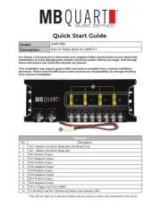
Congratulations on your choice of a MB Quart Auxiliary
Camera. This “Quick Start” Installation guide is meant to
help you complete a basic installation. Visit our website at
MBQuart.com for more detailed information.
Disconnect the negative battery terminal from the negative battery post
Locate your desired switch and camera location. Mount the switch in
an open carling knockout. If you do not have an open carling knockout,
the unit itself requires a 0.83 inch (21mm) wide by 1.4 inch (37mm)
high opening with at least 2.5 inches of clearance behind the mounting
•Route wiring labeled P2,P3,P7 to the switch location.
•Route purple reverse wire and yellow RCA video cables to the
•Route white 4 pin JST connector to the camera
•Route 12v, ACC, and GND wires to the vehicle battery or buss bar.
The camera comes with the ush mount already attached
(shown below). If your install location doesn’t allow for ush mounting,
please see surface mounting instructions on page 2.
To ush mount the camera, use the supplied 18.5mm hole saw to drill
the hole, making sure there is adequate room behind the panel.
Camera/Switch Installation
CAMERA SURFACE/BRACKET MOUNTING
To surface mount the camera, using the supplied bracket, unscrew
the ush mount trim ring that comes on the camera. Next, screw
on the surface mount bracket. Secure the bracket to the mounting
location you have chosen.
Note - may need to attach bracket to vehicle panel prior to attaching to camera.
Connect the white 4pin JST from the camera to the camera harness.
At this time you will connect the yellow RCA to the camera input of
your source unit or GMR7V1. Connect your camera’s reverse wire to
the camera trigger input on the radio. (See wiring diagram on page 4)
After all this is done, you can now connect the +12v, ACC, and GND
wires to the buss bar or battery and reconnect the negative battery
terminal to the negative battery post.
Camera/Switch Installation
Camera/Switch Installation
If using as a reverse camera only - cut the loop (green wire) located
on the camera wiring. Then connect the reverse wire to the reverse
trigger wire of your source unit to activate as a reverse camera.