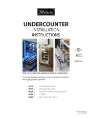
Perlick HP24 Manual


Læs nedenfor 📖 manual på dansk for Perlick HP24 (17 sider) i kategorien Køleskab. Denne guide var nyttig for 10 personer og blev bedømt med 4.5 stjerner i gennemsnit af 2 brugere

Side 1/17
Form No. Z2348
Rev. 04.01.2014
15” SIGNATURE SERIES
24” SIGNATURE SERIES
48” SIGNATURE SERIES
C-SERIES
ADA-COMPLIANT SERIES
18” SHALLOW-DEPTH SERIES
HP15
HP24
HP48
HC24
HA24
HH24
Installation Manual
PERLICK RESIDENTIAL INSTALLATION MANUAL
2perlick.com
TABLE OF CONTENTS
Warranty Information 2 .................................................................
Safety Information 4 .........................................................................
Plumbing, Electrical and General Information 4 .............
Installation Instructions 5 ..............................................................
Toe Kick Installation 7 .......................................................................
Shelving/Drawer Adjustments 8 ...............................................
CONGRATULATIONS
Congratulations on your purchase of a Perlick high quality
residential refrigeration product. Perlick’s innovative
product oering gives you the opportunity to enjoy the
functionality and user friendliness in just about any room of
your home, including kitchens, bedrooms, entertainment
rooms, basements and even bathrooms.
All Perlick products are built with commercial grade
stainless steel, providing you with the beauty and durability
for a lifetime of use. This installation guide will show you
how to properly install your new perlick product.
We dedicate considerable time to ensure that our products
provide the highest level of customer satisfaction. If,
however, service is required, call Perlick at 800.558.5592.
For your own protection, never return merchandise for
credit without our approval.
We thank you again for selecting a high quality Perlick
product. We hope you enjoy using it.
Model Number: _________________________________
Serial Number: _________________________________
Purchase Date: _________________________________
Dealer Name/Address:
______________________________________________
______________________________________________
______________________________________________
Phone Number: ________________________________
IMPORTANT!
Read and understand all information in this manual before attempting the installation. All
plumbing and electrical work must be performed by a qualified technician and conform to all
applicable state and local codes.
C
US
PERLICK RESIDENTIAL PRODUCTS WARRANTY
WARRANTY:
Perlick Corporation (“Perlick”) warrants to the original retail
purchaser that during the Basic Warranty Period, Perlicks
products will be free from free from defects in material and
workmanship, and during the Extended Warranty Period,
the hermetically sealed refrigeration system contained in
Perlicks undercounter refrigerator will be free from defects
in material and workmanship. This system consists entirely
of the compressor, condenser, drier, connecting tubing,
evaporator and hot gas bypass valve.
The Basic Warranty Period is as follows:
For a new product or oor display model, other than
the H50IM Clear Ice Maker: The three (3) year period
commencing on the date of purchase by the original
retail purchaser, except that the Basic Warranty Period
will be the two (2) year period commencing on the
date of purchase by the original retail purchaser if the
purchase of the product is not registered with Perlick
within ninety (90) days of purchase in the manner
described below.
For the H50IM Clear Ice Maker or a factory second (B-Stock)
product: The one (1) year period commencing on the
date of purchase by the original retail purchaser.
The Extended Warranty Period applies only to the
hermetically sealed refrigeration system contained
in Perlicks undercounter refrigerators. The Extended
Warranty Period is the portion of the six (6) year period
commencing on the date of purchase by the original retail
purchaser that is not covered by the Basic Warranty Period.
Door Information 8 ............................................................................
Changing the Door Swing Direction 8 .................................
Handle Installation 11 .........................................................................
Door Lock Installation 11 ..................................................................
Wood Overlay Installation 12 .........................................................
Wine Rack Trim ................................................................................. 12
PERLICK RESIDENTIAL INSTALLATION MANUAL
6perlick.com
PREPARING THE SPACE
If the unit is to be installed under
a countertop, it is recommended
that the countertop be supported by a structure other
than the unit itself to prevent damage to the unit.
Make sure the oor under the
unit is level with the surrounding
nished oor. Protect a nished oor with plywood,
cardboard, or some other suitable material before
moving the unit into place. Failure to do this may
result in damage to the oor.
1). Make sure the space opening is correctly sized for
the unit. See chart below for nished rough opening
requirements:
CAU NTIO
CAU NTIO
HP15 15” Signature Series
Height Depth Width
34-3/8” minimum,
35-1/2” maximum
24” 15”
HP24 24” Signature Series
Height Depth Width
34-3/8” minimum,
35-1/2” maximum
24” 24”
HP48 48” Signature Series
Height Depth Width
34-3/8” minimum,
35-1/2” maximum
24” 48”
HC24 24 C-Series
Height Depth Width
34-3/8” minimum,
35-1/2” maximum
24” 24”
HA24 24” ADA-Compliant Series
Height Depth Width
32-1/2” 24” 24”
HH24 18” Shallow-Depth Series
Height Depth Width
32-1/2” 18” 24”
NOTE: For a cabinet door to open properly, the door must
open a minimum of 90°. Use a minimum 3” ller in corner
installations to assure a full 90° opening. Allow 25” clearance
in front of unit for full door swing and shelf/drawer pull out for
all units.
2). Check that the following are level and square:
Front and interior opening
Installation opening and oor surface
Countertop bottom front edge
NOTE: The oor under the unit must be at the same level as the
surrounding nished oor.
To prevent possible damage to the
countertop, do not place heavy
objects on countertop directly over unit.
INSTALLING THE UNIT
1). Plug the unit into the 15 amp grounded electrical
outlet located within the installation opening. With power
applied to the unit, check that the lighting and cooling
functions operate properly. Turn o the power to the wall
outlet at the circuit breaker.
2). With all surfaces in the installation opening square and
level, refer to Figure 4 on page 7 and perform the following
steps to level the unit:
At the front of the opening, measure from the oor to
the bottom of the front edge of the countertop.
Measure from the oor surface to the top of the unit at
the rear corners.
Adjust the unit legs so these two measurements are
equal. Using an adjustable wrench or pliers, turn legs
clockwise to lower the unit or counterclockwise to raise it.
NOTE: Legs should not extend more than 3/4” from the bottom
of the unit.
3). Slide the unit into position in the opening. Make sure
the rear leveling legs slide under the ant-tip brackets. Push
the unit into the opening until the bottom front edge of
the unit is ush with the surrounding cabinetry, or until the
rear legs are tight against the anti-tip brackets.
4). Shim the front of the unit so the front face is ush
with the surrounding cabinetry. Adjust the front legs to
support the countertop at the shimmed height. Using
an adjustable wrench or pliers, turn the legs clockwise to
lower the unit or counterclockwise to raise it. Countertop
should be resting on top of the unit.
NOTE: Countertop should be resting evenly on entire top of the
unit. Shim if necessary to prevent damage to the countertop.
CAU NTIO
7
perlick.com
PERLICK RESIDENTIAL INSTALLATION MANUAL
5). Check interior door openings to make sure the unit is
level and square. Install shelving and/or drawers. Place
the slide brackets squarely into the bracket grooves.
When installed properly, a click” should be heard from the
slide bracket retaining tabs and the brackets should slide
smoothly. The retaining tabs will stop the shelf/drawer
when pulled out to full extension.
6). Turn on the power to the wall outlet at the circuit
breaker.
NOTE: Improper shelf/drawer installation may not actuate
slide mechanism.
Measure front of opening
from floor surface to bottom
edge of countertop
Measure at both rear corners of
unit from floor surface to bottom
of countertop
TOE PLATE INSTALLATION
Once the unit is secured in place, install the louvered toe
plate. Secure the plate by snapping the latch into the latch
catch on the unit (Figure 5).
The toe plate must be removed to
service the unit. The oor cannot
interfere with removal, and the louvered sections
must not be covered or obstructed. Obstructions could
prevent proper air circulation, which may damage the
unit.
NOTE: To achieve maximum performance, interior louver
openings and fan guard openings should never be obstructed.
CAU NTIO
Latch
Strike
Latch
Figure 4. Leveling the Unit
Figure 5. Toe Plate Installation
PERLICK RESIDENTIAL INSTALLATION MANUAL
8perlick.com
SHELVING/DRAWER ADJUSTMENTS
Completely empty shelf or drawer
before removing.
1. Pull the shelf/drawer out to its furthest position. Locate
the tabs in the middle of both extenders. Lift one tab up
while pushing the opposite tab down, and pull shelf/
drawer out (Figure 6).
2. Position each bracket separately. Grasp the middle of
the bracket, pull the front end up and out, then forward
to remove it.
3. Place bracket at desired location. Push the bracket rear
hook into the rear mounting slot, then set front of the
bracket in the front slot.
4. Repeat for other brackets.
5. Push extenders completely into brackets. Align the
shelf/drawer grooves with the extenders and slide
completely into the unit.
CAU NTIO
Lift one tab on extender UP while
pushing tab on opposite extender DOWN
and pull out to remove.
To remove brackets,
remove shelf, lift front
of bracket to disengage
the front key slot, then
pull forward to disengage
the rear key slot.
DOOR OPTIONS
Perlick residential units oer a variety of door panel design
alternatives; solid stainless steel, solid wood overlay, glass
with stainless steel trim and glass with wood overlay trim.
Solid stainless steel and stainless steel glass doors are
shipped from the factory with decorative stainless steel
panels and handles in place on the unit. Solid wood overlay
and glass wood overlay doors are designed to accept a
decorative front panel to match surrounding cabinetry
and door handles.
NOTE: Wood overlay models are designed to accept wood
overlay panels from your cabinetry supplier. They do not
include a wood overlay. Templates are available on www.
perlick.com/residential-products. Click on Service & Support,
and then choose Wood Overlay Templates from the menu.
Take care in choosing the correct template for your specic
model. The handle is supplied by the customer.
All Perlick units (excluding beer dispenser and ice maker
models) accept any of the above door congurations and
are fully interchangeable. Glass door congurations are not
available on beer dispenser or ice maker models.
NOTE: Glass with stainless steel trim and glass with wood trim
may sweat in conditions with relative humidity over 75%.
CHANGING DOOR SWING DIRECTION
NOTE: Changing the door mount is not advisable if the door is
equipped with a custom wood overlay. Doing so may result in
an undesirable handle position.
To change the door swing direction, a hinge kit is required:
Part No. 67439R - Right hinge kit
Part No. 67439L - Left hinge kit
In addition to the hinge kit, the following tools are required:
Large at head screwdriver
Regular Phillips head screwdriver
Plastic putty knife
1). Support the door in the open position as shown in
Fig. 7 on page 9. Remove the hinge pin.
2.) Pull door to the side and then lower door.
3.) Remove top and bottom hinge brackets. Retain screws
for later use. See Fig. 8 on page 9.
4). Remove the hole plugs from the top and bottom hinge
bracket mounting holes (see Fig. 8 on page 9). Place the
plugs in the holes on the opposite side made vacant by
removing the hinges in step 3.
Figure 5. Shelving/Drawer Adjustment


Produkt Specifikationer

Mærke: Perlick
Kategori: Køleskab
Model: HP24

Har du brug for hjælp?

Hvis du har brug for hjælp til Perlick HP24 stil et spørgsmål nedenfor, og andre brugere vil svare dig


Køleskab Perlick Manualer

Perlick

Perlick CR30R-1 Manual

10 December 2024
Perlick

Perlick CR24R-1 Manual

10 December 2024
Perlick

Perlick HP15BM-4 Manual

5 September 2024
Perlick

Perlick HP24ZS-4 Manual

5 September 2024
Perlick

Perlick HP24ZM-4 Manual

5 September 2024
Perlick

Perlick HP24CO-4 Manual

5 September 2024
Perlick

Perlick HH24RS-4 Manual

5 September 2024
Perlick

Perlick HP15RO-4 Manual

5 September 2024
Perlick

Perlick HP24RO-4 Manual

5 September 2024

Køleskab Manualer

Nyeste Køleskab Manualer