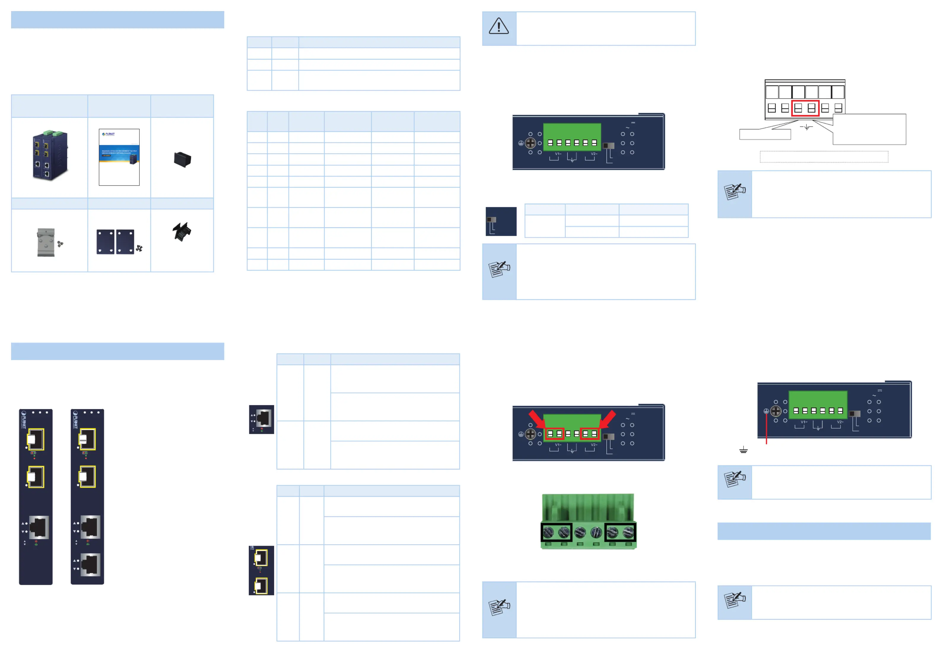
Planet IGT-2205AT Manual


Læs gratis den danske manual til Planet IGT-2205AT (2 sider) i kategorien Ikke kategoriseret. Denne vejledning er vurderet som hjælpsom af 87 personer og har en gennemsnitlig bedømmelse på 4.5 stjerner ud af 44 anmeldelser. Har du et spørgsmål om Planet IGT-2205AT, eller vil du spørge andre brugere om produktet?

Side 1/2
- 1 -
- 2 -
- 3 -
- 4 -
- 5 -
- 6 -
- 7 -
- 8 -
1. Package Contents
Thank you for purchasing PLANET industrial Gigabit Media Converter,
IGT-1205AT or IGT-2205AT. In the following sections, the term
Industrial Gigabit Media Converter mentioned in this users
manual also means the IGT-x205AT.
Open the box of the Industrial Gigabit Media Converter and carefully
unpack it. The box should contain the following items:
Converterx 1
Users Manual x 1 SFP Dust Cap x 2
DIN-rail Kit x 1 Wall-mount Kit x 1 RJ45 Dust Cap
IGT-1205AT x 1
IGT-2205AT x 2
If any of these are missing or damaged, please contact your dealer
immediately; if possible, retain the carton including the original packing
material, and use them again to repack the product in case there is a
need to return it to us for repair.
2.2 LED Indicators
System
LED Color Function
P1 Green Lit: Indicates power 1 has power.
P2 Green Lit: Indicates power 2 has power.
Alarm Red
Lit: Indicates one or more of the following events
are triggering the alarm (LED).
Alarm LED denition
PWR1 PWR2 DIP
Fiber Port
Link Status
Alarm LED
FAULT Alarm
OUTPUT
NO NO NO- - -
YES YES Switch - O Normal Close
YES Switch OnNO - Fault Open
NO YES Switch On- Fault Open
YES YES Redundant Primary ON O Normal Close
YES YES Redundant
Primary
DOWN
Slow blink
for 2 seconds
Fault Open
YES RedundantNO
Primary
DOWN
Blink rapidly Fault Open
NO YES Redundant
Primary
DOWN
Blink rapidly Fault Open
YES Redundant OnNO Primary ON Fault Open
NO YES Redundant OnPrimary ON Fault Open
2.5 Wiring the Fault Alarm Contact
The fault alarm contacts are in the middle of the terminal block
connector as the picture shows below. When inserting the wires, the
Industrial Gigabit Media Converter will detect the fault status of the
power failure and then forms an open circuit. The following illustration
shows an application example for wiring the fault alarm contacts.
Fault Alarm Contacts
The Fault Alarm Contacts are
energized (CLOSE) for normal
operation and will OPEN when
failure occurs
Alarm
1 2 3 4 5 6
Insert the wires into the fault alarm contacts
Note
1. The wire gauge for the terminal block should be in the
range between 12 and 24 AWG
2. Alarm relay circuit accepts up to 24V DC, max. 1A
currents.
Caution
Although 2.5G LED is a bi-color light, the actual color is
close to Amber.
2.3 Converter Upper Panel
The upper panels of the IGT-x205AT consist of one terminal block
connector within two DC power inputs, and the IGT-x205AT also
provides one DIP switch for ber redundant function. Figure 2-3 shows
the upper panel of the IGT-x205AT.
DC Input: 12-48V
, 0.6A
AC Input: 24V
, 0.6A
Switch
Redundant
Fiber
Mode
V1+
V2+
PWR1
PWR2Alarm
Max. Fault Alarm Loading: 24V, 1A
1 2 3 4 5 6
Figure 2-3: IGT-x205AT Upper Panel
The DIP switch settings and descriptions of the IGT-x205AT
Switch
Redundant
Fiber
Mode
DIP Position Function
Fiber Mode
ON Fiber Redundancy
OFF (default) Switch Mode
Note
1. If using the Switch mode, the IGT-x205AT can use 3
or 4 ports.
2. If using the , one of the two Fiber Redundant mode
ports will be redundant while the other 1 or 2 copper
ports are in operation.
2. Hardware Introduction
2.1 Converter Front Panel
Figures 2-1 and 2-2 show the front panels of the Industrial Gigabit
Media Converters.
LNK/ACT
LNK/ACT
10/100
1000
LNK /
ACT
LNK /
ACT
SFP
P1 P2 Alarm
100/1G/2.5G
100/1G/2.5G
SFP
2
1
2.5G
1000
100
IGT-1205AT
10/100/1000T
3
LNK /
ACT
LNK /
ACT
SFP
P1 P2 Alarm
100/1G/2.5G
100/1G/2.5G
SFP
2
1
2.5G
1000
100
IGT-2205AT
10/100/1000T
3
4
LNK/ACT
LNK/ACT
10/100
1000
SFP Port
100/1000/2500BASE-X SFP port
for transceiver module, enables
to have a networking distance of
300 meters to 2km (multi-mode
ber) and 10/20/40/60/80/120
kilometers (single-mode ber)
Gigabit TP Interface
10/100/1000BASE-T copper RJ45
twisted-pair with up to 100 meters
in distance.
Figure 2-1:
IGT-1205AT
Front Panel
Figure 2-2:
IGT-2205AT
Front Panel
Per 10/100/1000T Port
LNK/ACT
LNK/ACT
10/100
1000
10/100/1000T
3
LED Color Function
10/100
LNK/
ACT
Amber
Lit: Indicates the link through that port
is successfully established at 10Mbps or
100Mbps.
Blinking: Indicates that the Media
Converter is actively sending or receiving
data over that port.
1000
LNK/
ACT
Green
Lit: Indicates the link through that port
is successfully established at 1000Mbps.
Blinking: Indicates that the Media
Converter is actively sending or receiving
data over that port.
Per 100/1000/2500X SFP Port
LNK /
ACT
LNK /
ACT
SFP
100/1G/2.5G
100/1G/2.5G
SFP
2
1
2.5G
1000
100
LED Color Function
100
LNK/
ACT
Amber
Lit: Indicates the link through that port is
successfully established at 100Mbps.
Blinking: Indicates that the Media
Converter is actively sending or receiving
data over that port.
1000
LNK/
ACT
Green
Lit: Indicates the link through that port is
successfully established at 1000Mbps.
Blinking: Indicates that the Media
Converter is actively sending or receiving
data over that port.
2500
LNK/
ACT
Amber
+
Green
Lit: Indicates the link through that port is
successfully established at 2500Mbps.
Blinking: Indicates that the Media
Converter is actively sending or receiving
data over that port.
2.4 Wiring the Power Inputs
The 6-contact terminal block connector on the top panel of Industrial
Gigabit Media Converter is used for two DC redundant power inputs.
Please follow the steps below to insert the power wire.
1. Insert positive / negative DC power wires into contacts 1 and 2 for
POWER 1, or 5 and 6 for POWER 2.
DC I put: 12-48V
, 0.6A
A nput: 24V
, 0.6A
Switch
Redundant
Fiber
Mode
V1+
V2+
PWR1
PWR2Alarm
Max. Fault Alarm Loading: 24V, 1A
1 2 3 4 5 6
2. Tighten the wire-clamp screws for preventing the wires from loos-
ening.
1 2 4 53 6
Power 1 Power 2Alarm
+ - + -
Note
1. The wire gauge for the terminal block should be in the
range between 12 and 24 AWG.
2. The DC power input range is 12V ~ 48V DC and
supports 24V AC.
3. Use one power input when using 24V AC.
2.6 Grounding the Device
Users MUST complete grounding wired with the device; otherwise, a
sudden lightning could cause fatal damage to the device.
DC Input: 12-48V
, 0.6A
AC Input: 24V
, 0.6A
Switch
Redundant
Fiber
Mode
V1+
V2+
PWR1
PWR2Alarm
Max. Fault Alarm Loading: 24V, 1A
1 2 3 4 5 6
Earth Ground
Note
EMD (Lightning) DAMAGE IS NOT CONVERED UNDER
WARRANTY.
3. Installation
This section describes the functionalities of the Industrial Gigabit Media
Converters components and guides how to install it on the DIN-rail
and wall. Basic knowledge of networking is assumed. Please read this
chapter completely before continuing.
Note
This following pictures show the user how to install the
device, and the device is not IGT-x205AT.
- 9 -
- 10 -
- 11 -
- 12 - - 13 - - 14 -
3.1 DIN-rail Mounting Installation
1
2
3.2 Wall-mount Plate Mounting
3.3 Side Wall-mount Plate Mounting
Caution
You must use the screws supplied with the wall-
mounting brackets. Damage caused to the parts by
using incorrect screws would invalidate your warranty.
3.3 Installing the SFP Transceiver
The sections describe how to insert an SFP transceiver into an SFP
port.
The SFP transceivers are hot-pluggable and hot-swappable. You can
plug in and out the transceiver to/from any SFP port without having
to power down the Industrial Gigabit Media Converter as Figure 3-1
shows.
MGB / MFB
Series Module
Figure 3-1: Inserting the SFP Transceiver
Note
It is recommended to use PLANET SFP transceiver on
the Industrial Gigabit Media Converter. If you insert an
SFP transceiver that is not supported, the Industrial
Gigabit Media Converter will not recognize it.
4. Product Specications
Model IGT-1205AT IGT-2205AT
Hardware Specications
Copper Interface
1 x 10/100/1000BASE-T
RJ45
2 x 10/100/1000BASE-T
RJ45
Fiber Optic
Interfaces
2 x 100/1G/2.5GBASE-X SFP interfaces
(Port-1 and Port-2)
Supports auto detection
Connector
Removable 6-pin terminal block
Pin 1/2 for Power 1;
Pin 3/4 for fault alarm;
Pin 5/6 for Power 2
DIP Switch
DIP Position Function
Fiber
Mode
ON Fiber Redundancy
OFF (default) Switch Mode
Alarm
Provides one relay output for power failure
Alarm Relay current carry ability: 1A @ DC 24V
Power
Requirements
DC 12~48V or AC 24V
Redundant power with reverse polarity protection
Power
Consumption /
Dissipation
4.8 watts/16BTU 4.92 watts/16.9BTU
Dimensions
(W x D x H)
32 x 87 x 135mm 32 x 87 x 135mm
Weight 412g 419g
Enclosure IP30 type metal case
Installation DIN-rail kit and wall mount ear
ESD Protection 6KV DC
Converter Specications
Processing
Scheme
Store-and-Forward
Fabric 12Gbps 14Gbps
Throughput
(packet per
second)
8.93Mpps@64bytes 10.42Mpps@64bytes
Flow Control
Back pressure for half duplex.
IEEE 802.3x pause frame for full duplex
Address Table 4K entries
Jumbo Frame 9216bytes
Standards Conformance
Standards
Compliance
IEEE 802.3 Ethernet
IEEE 802.3u Fast Ethernet
IEEE 802.3ab Gigabit Ethernet
IEEE 802.3z Gigabit Ethernet 1000BASE-SX/LX
IEEE 802.3x Full-Duplex Flow Control
IEEE 802.1p Class of Service
Regulatory
Compliance
FCC Part 15 Class A, CE
Stability Testing
IEC60068-2-32 (free fall)
IEC60068-2-27 (shock)
IEC60068-2-6 (vibration)
Environment
Temperature
Operating: -40~75 degrees C
Storage: -40~75 degrees C
Humidity
Operating: 5~95% (non-condensing)
Storage: 5~95% (non-condensing)
PLANET Industrial Gigabit Media Converter supports 100/1000/2500X
with both single mode and multi-mode SFP transceivers. Before we
connect Industrial Gigabit Media Converter to the other network device,
please do the following:
1. Set the DIP Switch of SFP Port 1 or Port 2 to the position OFF
with ber speed auto detection.
DIP Position Function
Fiber Mode
ON Fiber Redundancy
OFF (default) Switch Mode
2. Make sure both sides of the SFP transceivers are with the same
media type, for example, 1000BASE-SX to 1000BASE-SX, and
1000BASE-LX to 1000BASE-LX.
Note
Never pull out the module without pulling the lever or
the push bolts on the module. Directly pulling out the
module with force could damage the module and the
SFP port of the Industrial Gigabit Media Converter.
5. Customer Support
Thank you for purchasing PLANET products. You can browse our online
FAQ resource on PLANET web site rst to check if it could solve your
issue. If you need more support information, please contact PLANET
switch support team.
PLANET online FAQs:
http://www.planet.com.tw/en/support/faq
Switch support team mail address:
support@planet.com.tw
Copyright © PLANET Technology Corp. 2022.
Contents are subject to revision without prior notice.
PLANET is a registered trademark of PLANET Technology Corp.
All other trademarks belong to their respective owners.


Produkt Specifikationer

Mærke: Planet
Kategori: Ikke kategoriseret
Model: IGT-2205AT
Kode for international beskyttelse (IP): IP30
Bredde: 32 mm
Dybde: 87 mm
Højde: 135 mm
Vægt: 419 g
Produktfarve: Blå
Opbevaringstemperatur (T-T): -40 - 75 °C
Relativ luftfugtighed ved drift (H-H): 5 - 95 %
Relativ luftfugtighed ved opbevaring (H-H): 5 - 95 %
Ethernet LAN-porte (RJ-45): 2
Driftstemperatur (T-T): -40 - 75 °C
Husmateriale: Metal
Certificering: FCC Part 15 Class A, CE
Netværksstandarder: IEEE 802.1p, IEEE 802.3, IEEE 802.3ab, IEEE 802.3u, IEEE 802.3x, IEEE 802.3z
LED-indikatorer: Ja
Fiber optisk strømstik: SFP
Auto MDI/MDI-X: Ja
Opbevar-og-frem: Ja
Jumbo Frames support: Ja
Jumbo rammer: 9000
DIN-skinne montering: Ja
Auto-forhandling: Ja
Fiberkanal porte: 2

Har du brug for hjælp?

Hvis du har brug for hjælp til Planet IGT-2205AT stil et spørgsmål nedenfor, og andre brugere vil svare dig


Ikke kategoriseret Planet Manualer

Ikke kategoriseret Manualer

Nyeste Ikke kategoriseret Manualer

JILONG

JILONG JL097205NPF Manual

14 September 2025
Brandson

Brandson 306570 Manual

14 September 2025
Nedis

Nedis PIM30012EGY Manual

14 September 2025
Neutrik

Neutrik SCD-W Manual

14 September 2025
BSS Audio

BSS Audio FCS-926 Manual

14 September 2025
Brandson

Brandson 303842 Manual

14 September 2025
AMX

AMX DGX-O-DXF-MMS Manual

14 September 2025
Brandson

Brandson 304024 Manual

14 September 2025
JILONG

JILONG JL097109NPF Manual

14 September 2025
Brandson

Brandson 303403 Manual

14 September 2025