Planet LN1152 Manual


Læs gratis den danske manual til Planet LN1152 (2 sider) i kategorien Ikke kategoriseret. Denne vejledning er vurderet som hjælpsom af 21 personer og har en gennemsnitlig bedømmelse på 4.3 stjerner ud af 11 anmeldelser. Har du et spørgsmål om Planet LN1152, eller vil du spørge andre brugere om produktet?

Side 1/2
- 1 -
- 2 -
- 3 -
- 4 -
- 5 -
- 6 -
- 7 -
- 8 -
1. Package Contents
Thank you for purchasing PLANET Industrial LoRa Node Controller,
LN series. The descriptions of these models are as follows:
LN501 Outdoor IP67 LoRa Node Controller with Solar Panel
LN1152 Indoor IP30 LoRa Node Controller
LoRa Node is used as an alternative name in this Quick
Open the box of the and carefully unpack it. The box LoRa Node
should contain the following items:
LN501 LN1152
LoRa Node Controller x 1
Quick Installation Guide x 1
Data Cables x 2
Mounting Bracket x 1
Wall Mounting Kits x 1
Hose Clamps x 2
2550 mAh Battery x 2
LoRa Node Controller x 1
Quick Installation Guide x 1
LoRa Antenna x 1
12-Pin Terminal Block x 1
Wall Mounting Screws x 2
Power Adapter x 1
If any item is found missing or damaged, please contact your local
reseller for replacement.
Caution
1. Never put batteries in mouth. If swallowed, contact
your physician or local poison control center.
2. Do not short circuit; may cause burns or catch fire.
3. Batteries should not be exposed to excessive heat
such as sunshine, fire or the like.
3. Hardware Installation
Refer to the illustration and follow the simple steps below to
quickly install your LoRa Node.
3.1 LN501
3.1.1 Remove cover for setting analog input or power
output
When changing the analog input or power output of LN501 via DIP
switch, follow the steps below:
Step 1: Removethescrewcapsandtakeotheroofcover.
3.1.3 Wall Mounting
Make sure you have a wall mounting bracket, bracket mounting
screws, wall plugs, wall mounting screws and other required tools.
Step 1: Mark the four holes on the wall you prefer to place the
device and drill the marked four holes for the wall plugs
(anchors). Then place the mounting bracket over the
holes with the wall plugs inside, and tighten it with the
screws.
Step 2: Place the device on the mounting bracket and put the
small screw into the hole found on the bottom of the
deviceandthentightenthescrewtonishthejob.
3.1.4 Pole Mounting
Step 1: Straighten out the clamp and slide it through the
rectangular rings in the mounting bracket, and wrap the
clamp around the pole. Then use a screwdriver to tighten
the clamp by turning it clockwise.
Power Button:
Function Action LED Indication
Turn On
Press and hold the button
for more than 3s.
O On
TurnO
Press and hold the button
for more than 3s.
On O
Reset
Press and hold the button
for more than 10s.
Blinks.
CheckOn/O
Status
Quickly press the power
button.
Light On: Device is on.
LightO:Deviceiso.
Note
Please turn off the device before changing DIP
switches.
Step 3: Put back the roof cover and screw the screws.
Note
1. Analog input is set to 4-20mA by default; power
output is set to 12V by default.
2. Power output on interface 1 is used for powering
serial port devices and power output on interface 2
is used for powering analog devices.
2. Requirements
Workstations running Windows 10/XP/2003/Vista/7/8/2008.
Type C USB cable for LN501.
Micro USB cable for LN1152.
Step 2: Choose or change an analog input and power output via
DIP switch.
DIP Switch:
Interface DIP Switch
Power
Output
12V:1on2o3o(default)
9V:1o2on3o
5V:1o2o3on
Analog
Input
Disable:1o2o3o
4-20mAADC:1o2on3on(default)
0-10VADC:1on2o3o
RS485
Disable:1o2o3o(default)
Add120ΩresistorbetweenAandB:1on2o3o
Add1kΩpull-upresistoronA:1o2on3o
Add1kΩpull-downresistoronB:1o2o3on
3.1.2 Data Interface
Data Interface 1
Pin Description
1 5V/9V/12V OUT (Switchable)
2 3.3V OUT
3 GND
4 Analog Input 1
5 Analog Input 2
6 5-24V DC IN
Data Interface 2
Pin Description
1 5V/9V/12V OUT (Switchable)
2 3.3V OUT
3 GND
4 GPIO1
5 GPIO2
6
RS232/RS485 (Switchable)
7
8 Reserved
PIN RS232 RS485
6 ATx
7 BRx
Step 2: Place the device on the mounting bracket and put the
small screw into the hole found on the bottom of the
deviceandthentightenthescrewtonishthejob.
Note
Please make sure the screws are tightly fixed.
3.2 LN1152
3.2.1 Antenna Installation
Step 1: Rotate the antenna into the antenna connector
accordingly.
Step 2: The external LoRa antenna should be installed vertically
for a good signal.


Produkt Specifikationer

Mærke: Planet
Kategori: Ikke kategoriseret
Model: LN1152
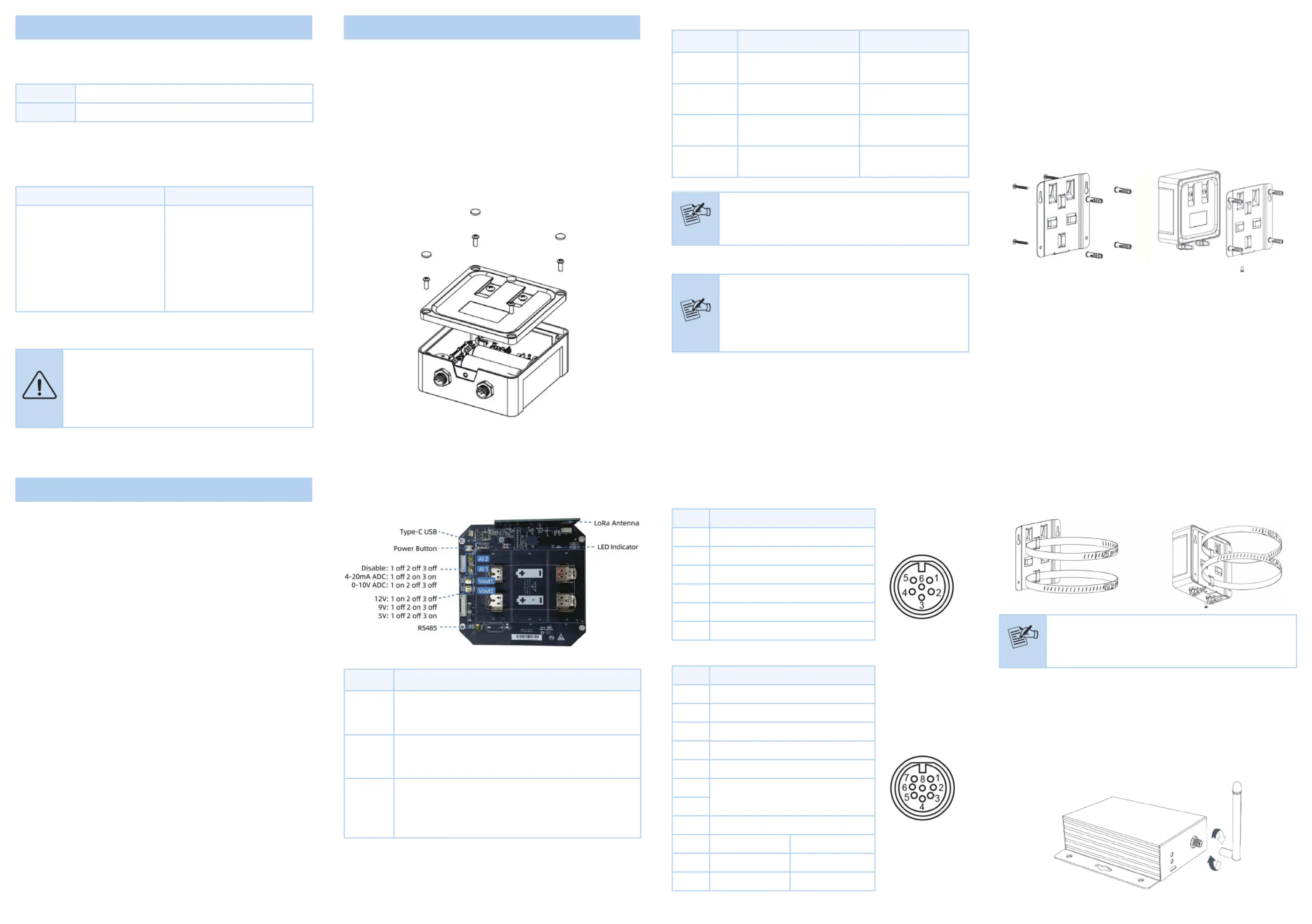
Kode for international beskyttelse (IP): IP30
Bredde: 79 mm
Dybde: 60 mm
Højde: 24 mm
Brugervejledning: Ja
Produktfarve: Sort
Driftstemperatur (T-T): -40 - 70 °C
Hurtig start guide: Ja
Certificering: CE, FCC
Antenner, antal: 1
LED-indikatorer: Activity, System
Udgangsspænding: 30 V
Monteringstype: Skrivebords-/vægmontering
Bæredygtighedscertifikater: CE, Federal Communications Commission (FCC)
DC indgangsspænding: 3 - 24 V
Antenne type: Ekstern
Indgangsstrøm: 3 A
RS-232-porte: 1
Understøttede protokoller: Transparent (RS232), Modbus RTU (RS485)
Relativ luftfugtighed: 0 - 95 %
Antennestik type: SMA
Administrationsplatform: IN865, EU868, RU864

Har du brug for hjælp?

Hvis du har brug for hjælp til Planet LN1152 stil et spørgsmål nedenfor, og andre brugere vil svare dig


Ikke kategoriseret Planet Manualer

Ikke kategoriseret Manualer

Nyeste Ikke kategoriseret Manualer

DS18

DS18 VOC8PRO Manual

5 November 2025
Icron

Icron Rover 2850 Manual

5 November 2025
Amaran

Amaran Peak Manual

5 November 2025
WesAudio

WesAudio Timbre Manual

5 November 2025
MuxLab

MuxLab 500800-TX Manual

5 November 2025
MSI

MSI MS-ND82 Manual

5 November 2025