1. Read these instructions.
2. Keep these instructions.
3. Heed all warnings.
4. Follow all instructions.
5. Do not use this apparatus near water.
6. Clean only with dry cloth.
7. Do not block any ventilation openings. Install in accordance with
the manufacturer’s instructions.
8. Do not install near any heat sources such as radiators, heat registers,
stoves, or other apparatus (including amplifiers) that produce heat.
9. Do not defeat the safety purpose of the polarized or grounding-type
plug. A polarized plug has two blades with one wider than the other.
A grounding-type plug has two blades and a third grounding prong.
The wide blade or the third prong are provided for your safety. If the
provided plug does not fit fully into your outlet, consult an electrician
for replacement of the obsolete outlet.
10. Protect the power cord from being walked on or pinched particu-
larly at plugs, convenience receptacles, and the point where they
exit from the apparatus.
11. Only use attachments/accessories specified by the
manufacturer.
12. Use only with the cart, stand, tripod, bracket, or table specified by
the manufacturer, or sold with the apparatus.
When a cart is used, use caution when moving
the cart/apparatus combination to avoid injury
from tip-over.
13. Unplug this apparatus during lightning storms
or when unused for long periods of time.
14. Refer all servicing to qualified service personnel. Servicing is
required when the apparatus has been damaged in any way, such
as power-supply cord or plug is damaged, liquid has been spilled
or objects have fallen into the apparatus, the apparatus has been
exposed to rain or moisture, does not operate normally, or has
been dropped.
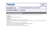
15. If an outside antenna is connected to the television equipment, be
sure the antenna system is grounded so as to provide some protec-
tion against voltage surges and built up static charges. In the U.S.
Selection 810-21 of the National Electrical Code provides informa-
tion with respect to proper grounding of the mast and supporting
structure, grounding of the lead-in wire to an antenna discharge
unit, size of grounding conductors, location of antenna discharge
unit, connection to grounding electrodes, and requirements for the
grounding electrodes.
16. An outside antenna system should not be located in the vicinity of
overhead power lines or other electrical light or power circuits, or
where it can fall into such lines or circuits. When installing an outside
antenna system, extreme care should be taken to keep from touching
such power lines or circuits as contact with them might be fatal.
EXAMPLE OF ANTENNA GROUNDING ACCORDING
TO NATIONAL ELECTRICAL CODE, ANSI/NFPA 70
“Note to CATV system installer:
This reminder is provided to call the CATV system installer’s attention
to Article 820-40 of the NEC that provides guidelines for proper
grounding and, in particular, specifies that the cable ground shall be
connected to the grounding system of the building, as close to the
point of cable entry as practical.”
17. Wall or Ceiling Mounting—The product should be mounted to a
wall or ceiling only as recommended by the manufacturer.
18. Apparatus shall not be exposed to dripping or splashing, and no
objects filled with liquids, such as vases, shall be placed on it.
19. When the MAINS plug is used as the disconnect device, the dis-
connect device shall remain readily operable.
RISK OF ELECTRIC SHOCK DO NOT OPEN!
CAUTION: TO REDUCE RISK OF ELECTRIC SHOCK, DO NOT RE OVE COVER (OR BACK). NOM
USER-SERVICEABLE PARTS INSIDE. REFER SERVICING TO QUALIFIED SERVICE PERSONNEL.
THIS SYMBOL INDICATES THAT DANGEROUS VOLTAGE CONSTITUTING A RISK
OF ELECTRIC SHOCK IS PRESENT WITHIN THIS UNIT.
THIS SYMBOL INDICATES THAT THERE ARE IMPORTANT OPERATING AND MAINTE-
NANCE INSTRUCTIONS IN THE LITERATURE ACCOMPANYING THIS UNIT.
WARNING: TO REDUCE THE RISK OF FIRE OR ELECTRIC SHOCK, DO NOT EXPOSE THIS APPLIANCE TO RAIN OR MOISTURE.
IMPORTANT SAFETY INSTRUCTIONS
CAUTION
FCC INFORMATION ________________________________________________
This equipment has been tested and found to comply with the limits for a Class B digital device, pursuant to Part 15 of the FCC Rules. These
limits are designed to provide reasonable protection against harmful interference in a residential installation. This equipment generates,
uses and can radiate radio frequency energy and, if not installed and used in accordance with the instructions, may cause harmful interfer-
ence to radio communications. However, there is no guarantee that interference will not occur in a particular installation. If this equipment
does cause harmful interference to radio or television reception, which can be determined by turning the equipment off and on, the user is
encouraged to try to correct the interference by one or more of the following measures:
– Reorient or relocate the receiving antenna.
– Increase the separation between the equipment and receiver.
– Connect the equipment into an outlet on a circuit different from that to which the receiver is connected.
– Consult the dealer or an experienced radio/TV technician for help.
CAUTION: FCC Regulations state that improper modifications or unauthorized changes to this unit may void the user’s authority to
operate the unit.
Please read before operating your HDTV!
PROTECTING THE LCD
SCREEN
CAUTION: The screen can be damaged if
it is not maintained properly.
•Do not use hard objects such as hard
cloth or paper to clean the screen.
•Do not use excessive pressure when
cleaning the screen; excessive pressure
can cause permanent discoloration or
dark spots.
•NEVER spray liquids on the screen.
HANDLING PRECAUTIONS
•Handle by the cabinet only.
•Handling by two or more people is
recommended.
•Never touch the screen when handling.
•Handling damage is covered undernot
warranty.
•Do not remove the protective film
covering the front cabinet while
handling the HDTV.
POSITIONING THE HDTV
•Always use a firm and flat surface when
positioning your HDTV.
•Do not position the unit in a confined
area.
•Allow adequate space for proper venti-
lation.
•Do not position the HDTV where it is
easily reachable by small children and
may present risk of injury.
•Once HDTV is positioned, remove the
protective film covering front cabinet.
WALL OUNTINGM(OPTIONAL)
NOTE: Skip these steps if using a wall
mounting kit (not included).
1Place HDTV face down on a
padded or cushioned flat surface
to protect the screen and finish.
2Carefully insert the stand base to
the bottom of the HDTV and secure
it by inserting four (4) screws as
indicated in the diagram below.
NOTE: Stand base screws are located
in the literature package.
3Position the HDTV on a firm and
flat surface with adequate space
for proper ventilation.
STAND ASSEMBLY ______
GETTING STARTED
Install two (2) “AA” batteries in the
remote control. (Not included)
PRECAUTIONS:
• Replace both batteries at the same
time. Do not use a new battery with
an old used battery.
• There’s a risk of explosion if a battery
is replaced by an incorrect type.
• Keep away from moisture.
• Be sure to match the “+” and “–”
signs on the batteries with marks
inside the remote control.
• Please properly dispose of used up
batteries.
WARNING: The batteries (or battery
pack) shall not be exposed to excessive
heat such as sunshine, fire or the like.
BATTERY INSTALLATION
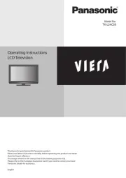
Hook up your antenna or your cable
service to the HDTV’s ANT terminal
with the use of a 75 OHM coaxial cable.
NOTE: Keep your indoor antenna at
least 3 ft. away from the televi-
sion set and any other electron-
ic equipment.
The tuner in this HDTV can receive:
• Digital and Analog off air signals
from an antenna
• Analog or ClearQAM cable channels
from a direct Cable TV connection.
ANTENNA CONNECTION FOR
OFF-AIR SIGNALS OR CABLE
ANTENNA
CABLE
ANALOG / DIGITAL
ANTENNA IN
AV INPUT SELECTION
Press the key to select the INPUT
correct AV input for the video source
you wish to watch.
NOTE: Unused AV inputs may be dis-
abled with the Input Setting feature.
HDTV LCD
Owner’s
Manual
(English)
Model No.:
DP46812
Sanyo Manufacturing Corp. 3333
Sanyo Road, Forrest City, AR 72335
This equipment is a Class II or double insulated electrical appliance. It has been designed in such a way that it does not require
a safety connection to electrical earth.
The American Academy of Pediatrics dis-
courages media use by children younger
than two years. For more information,
visit www.aap.org.
SPECIFICATIONS
Power Requirement:
Source: AC 120V, 60Hz
AC Power Consumption: 178 watts
Weight (w/stand) - 41 lbs.
Dimensions _________________________
WIDTH HEIGHT DEPTH
DP46812 43.9 29.4 10.6
w/out stand 43.9 26.6 4.4
NOTE: Dimensions are in inches
SANYO television customers
should contact MRM Recycling at
888-769-0149 or visit their website
at www.mrmrecycling.com regar-
ding SANYO’s waste manage-
ment plan.
CONTAINS ERCURYM
LAMPS, DISPOSE OF
PROPERLY
As an Energy Star®Partner,
Sanyo Manufacturing Corporation
has determined that this product
meets the Energy Star®guide-
lines for energy efficiency.
ENERGY STAR
TRADE ARKSM________
Manufactured under license from Dolby
Laboratories. “Dolby” is a trademark of
Dolby Laboratories.
HDMI, the HDMI Logo and High-Definition
Multimedia Interface are trademarks or regis-
tered trademarks of HDMI Licensing LLC in
the United States and other countries.
Manufactured under license from Audyssey
Laboratories
TM . U.S. and foreign patents pend-
ing. Audyssey Dynamic Volume®is a registered
trademark of Audyssey Laboratories.
ENERGY STAR is a set of power-saving guidelines issued by the U.S. Environmental Protection
Agency (EPA). ENERGY STAR is a joint program of the U.S. Environmental Protection Agency
and the U.S. Department of Energy helping us all save money and protect the environment
through energy efficient products and practices.
Changes to default as-shipped television configuration and settings or enabling certain optional
features and functionalities will change the energy consumption of the television, this may
increase energy consumption beyond the limits required for ENERGY STAR qualification.
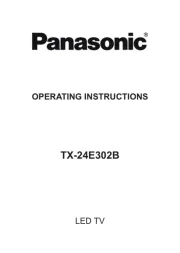
HDTV INPUT/OUTPUT REFERENCE ________________________________________
HDTV BACK PANEL
HDTV SIDE PANEL
3
HDMI (INPUT1 or INPUT2)
Use HDMI INPUT1 & 2 to hookup HD digital devices such as
a Blu-ray player, HD Cable Box, HD Satellite Receiver or
Video-game System.
Connect your digital device’s HDMI output to any of the two
(2) HDMI inputs on your HDTV with the use of an HDMI cable.
USB
USB input jack is used to connect a USB mass storage
device to watch digital images stored in JPEG format.
Digital Audio Output (Coaxial)
Hookup a multichannel receiver with the use of a phono-
type digital audio cable.
Analog / Digital Antenna Input
Hook up your indoor or outdoor digital antenna, or a direct
Cable service (Analog or ClearQAM).
VIDEO INPUT (CO POSITE combo)MPONENT/COM
COMPOSITE Connection
A Composite connection is used to hookup your analog
equipment such as a VCR or an older DVD player.
Match the YELLOW connector from your external device to
the GREEN Y-VIDEO jack on the HDTV.
NOTE: Use the WHITE and RED (L and R) jacks for AUDIO
signal.
COMPONENT Connection
A Component connection will accept SDTV, EDTV and
HDTV video signals. Use it for great image quality from di-
gital devices such as a DVD player or Video Game system.
Match your digital device’s Component output jacks to the
Component input jack set on your HDTV.
NOTE: Use the GREEN (Y), BLUE (Pb) and RED (Pr) jacks for the
VIDEO signal and the WHITE and RED (L and R) jacks for
the AUDIO signal.
1
2
3
4
5
Printed in Mexico, August 2012
US2R / 46-Z5WPP / GXFA
2
This device complies with Part 15 of the FCC Rules. Operation is subject to the following two conditions: (1) this device may not cause
harmful interference, and (2) this device must accept any interference received, including interference that may cause undesired operation.
Shielded cables must be used with this unit to ensure compliance with the Class B FCC limits.
Wall mounting of the HDTV must be
performed by a skilled person.
If stand base disassembly is required:
•Place HDTV face down on a padded or
cushioned flat surface to protect the
screen and finish.
•Remove the four (4) screws securing
the foot stand. Hold theCAUTION:
stand firmly as you remove the last
screw.
Use the four (4) screws included in the
literature package (or removed from
the foot stand) to secure the HDTV to a
wall mounting kit.
IMPORTANT: Wall mount kit must
comply with VESA standard 400 x
400. All four (4) screws must be
threaded to the wall mount and
HDTV’s back cabinet
Mounting screws measurements:
M6 (6mm) Diameter, Length—12mm
(maximum)
1
4
5