Thames & Kosmos Physics Simple Machines Manual
Thames & Kosmos
Ikke kategoriseret
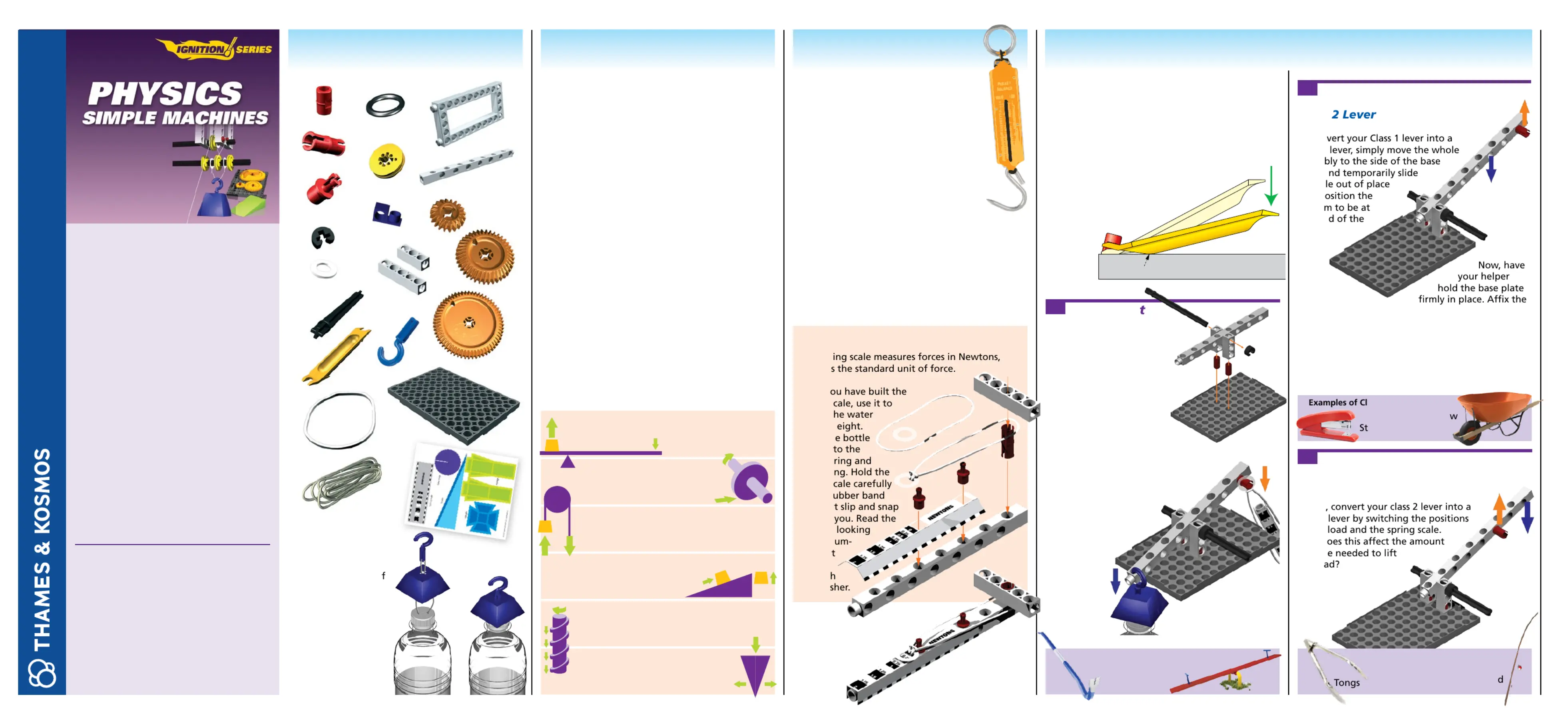
Physics Simple Machines
| Mærke: | Thames & Kosmos |
| Kategori: | Ikke kategoriseret |
| Model: | Physics Simple Machines |
Har du brug for hjælp?
Hvis du har brug for hjælp til Thames & Kosmos Physics Simple Machines stil et spørgsmål nedenfor, og andre brugere vil svare dig
Ikke kategoriseret Thames & Kosmos Manualer


2 Oktober 2025

2 Oktober 2025


7 August 2025

6 August 2025
6 August 2025
Ikke kategoriseret Manualer
- Elkay
- Faber
- Accu-Chek
- GMB Audio
- Techni Mobili
- Rocstor
- Horizon Fitness
- EMSA
- Tsakalis AudioWorks
- Lamar
- Lumens
- Kubota
- Wëasy
- Burgwachter
- Verbatim
Nyeste Ikke kategoriseret Manualer

15 December 2025

15 December 2025

15 December 2025

15 December 2025

15 December 2025

15 December 2025

15 December 2025

15 December 2025

15 December 2025

15 December 2025