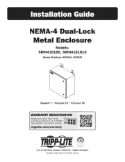
Tripp Lite DMCSD3545M Manual


Læs gratis den danske manual til Tripp Lite DMCSD3545M (80 sider) i kategorien Ikke kategoriseret. Denne vejledning er vurderet som hjælpsom af 13 personer og har en gennemsnitlig bedømmelse på 5.0 stjerner ud af 7 anmeldelser. Har du et spørgsmål om Tripp Lite DMCSD3545M, eller vil du spørge andre brugere om produktet?

Side 1/80
1111 W. 35th Street, Chicago, IL 60609 USA • www.tripplite.com/support
Copyright © 2019 Tripp Lite. All rights reserved.
Owner’s Manual
Dual Flat-Panel
Mobile Cart
Model: DMCSD3545M
200x200 / 300x200
300x300 / 400x200
400x300 / 400x400
45"
MAX 88 lb. x 2
(40 kg x 2)
TV
11 lb.
(5 kg)
DVD
11 lb.
(5 kg)
WEBCAM
Español 17 • Français 33 • Русский 49 • Deutsch 65
WARRANTY REGISTRATION
Register your product today and be
automatically entered to win an ISOBAR
surge protector in our monthly drawing!
www.tripplite.com/warranty
19-04-453-933909.indb 1 5/6/2019 11:33:25 AM
2
NOTE: Read the entire instruction manual before you start assembly and
installation.
Warranty and Product Registration
WARNING
Do not begin the installation until you have read and understood
the instructions and warnings contained in this manual. If you have
questions regarding any of the instructions or warnings, please visit
www.tripplite.com/support.
This product was designed to be installed and utilized ONLY as specified
in this manual. Improper installation of this product may cause damage
or serious injury.
This product should only be installed by someone of good mechanical
ability, with basic building experience and a full understanding of this
instruction manual.
Make sure the unit can safely support the combined load of the
equipment and all attached hardware and components.
Always use an assistant or mechanical lifting equipment to safely lift
and position equipment.
This product is intended for indoor use only. Using this product outdoors
could lead to product failure and/or personal injury.
5-Year Limited Warranty
Seller warrants this product, if used in accordance with all applicable instructions, to be free from original
defects in material and workmanship for a period of 5 years from the date of initial purchase. If the product
should prove defective in material or workmanship within that period, Seller will repair or replace the
product, in its sole discretion.
THIS WARRANTY DOES NOT APPLY TO NORMAL WEAR OR TO DAMAGE RESULTING FROM ACCIDENT,
MISUSE, ABUSE OR NEGLECT. SELLER MAKES NO EXPRESS WARRANTIES OTHER THAN THE WARRANTY
EXPRESSLY SET FORTH HEREIN. EXCEPT TO THE EXTENT PROHIBITED BY APPLICABLE LAW, ALL IMPLIED
WARRANTIES, INCLUDING ALL WARRANTIES OF MERCHANTABILITY OR FITNESS, ARE LIMITED IN DURATION
TO THE WARRANTY PERIOD SET FORTH ABOVE; AND THIS WARRANTY EXPRESSLY EXCLUDES ALL
INCIDENTAL AND CONSEQUENTIAL DAMAGES. (Some states do not allow limitations on how long an implied
warranty lasts, and some states do not allow the exclusion or limitation of incidental or consequential
damages, so the above limitations or exclusions may not apply to you. This warranty gives you specific legal
rights, and you may have other rights which vary from jurisdiction to jurisdiction).
WARNING: The individual user should take care to determine prior to use whether this device is suitable,
adequate or safe for the use intended. Since individual applications are subject to great variation, the
manufacturer makes no representation or warranty as to the suitability or fitness of these devices for any
specic application.
PRODUCT REGISTRATION
Visit www.tripplite.com/warranty today to register your new Tripp Lite product. You’ll be automatically entered
into a drawing for a chance to win a FREE Tripp Lite product!*
* No purchase necessary. Void where prohibited. Some restrictions apply. See website for details.
Tripp Lite has a policy of continuous improvement. Specications are subject to change without notice.
Photos and illustrations may differ slightly from actual products.
19-04-453-933909.indb 2 5/6/2019 11:33:25 AM
3
Component Checklist
IMPORTANT: Ensure you have received all parts according to the component
checklist prior to installing. If any parts are missing or faulty,
visit www.tripplite.com/support for service.
A
Left Plastic Cover
E
Universal Plate
H
Left Column
J
Left Adapter Brackets
L
Camera Shelf
P
Left Base
Q
Right Base
M
Connecting Plate
N
Crossbar
O
Support Bar
I
Right Column
K
Right Adapter Brackets
F
Top Covers
G
Cable Covers
B
Right Plastic Cover
C
Middle Base
D
DVD Shelf
19-04-453-933909.indb 3 5/6/2019 11:33:25 AM
4
Component Checklist
Package M
Package P
M-A
M5x14
M-B
M6x14
M-C
M8x20
M-D
M6x30
M-E
M8x30
M-F
Washer
M-G
Small Spacer
M-H
Big Spacer
P-I
M8x65
P-N
5 mm Hex Key
P-O
Wrench
P-J
M4x6
P-K
M4x6
P-L
D8 Washers
P-M
D6 Washers
P-C
M8x30
P-D
M8x40
P-E
M6x14
P-F
M6x25
P-G
M6x8
P-H
M6x14
P-A
Butterfly Nuts
P-B
Butterfly Nuts
19-04-453-933909.indb 4 5/6/2019 11:33:25 AM
5
Assembly
1Assemble the Base
Using M8x40 screws ( ) and the 5 mm hex key ( ), attach the right base to the P-D P-N
middle base. Repeat this step for the left base.
Note: Lock the brakes on the casters to avoid any sudden movements during installation.
Each caster can be adjusted independently for fine adjustments. Slightly turn each caster
nut to lower or raise the base.
P
C
Q
P-N
P-D
A
B
P-O
19-04-453-933909.indb 5 5/6/2019 11:33:26 AM
6
Assembly
2Attach the Columns to the Base
H
H
P-C
Pin
Pin
I
I
Inner
Column
V
Pull the pin outward and lift the inner column upward at the same time until the inner
column is at the desired height. Release the pin to secure.
Using M8x30 screws ( ), P-C
attach the columns to the base.
Tighten
the Safety
Screw.
19-04-453-933909.indb 6 5/6/2019 11:33:27 AM
7
Assembly
3
4
Install the Crossbar
Install the Cable Covers
Using M6x14
screws ( ), P-H
attach the crossbar
to the columns.
Once the crossbar
installation is
completed, use
the 5 mm hex key
( ) to tighten the P-N
bottom screws on
the base.
H
P-H
G
19-04-453-933909.indb 7 5/6/2019 11:33:28 AM
8
Assembly
5Install the Universal Plate
P-B P-L
P-I E
Using M8x65 screws ( ), P-I
D8 washers ( ) and buttery P-L
nuts ( ), attach the universal P-B
plate to the columns.
19-04-453-933909.indb 8 5/6/2019 11:33:29 AM
9
Assembly
6a
6Install the Adapter Brackets
Install the Adapter Brackets
For Flat-Back Screen
Note: Choose appropriate screws and washers according to the type of screen.
• Screw the adapter brackets onto the display.
Tighten all screws, but do not over-tighten.
Top of the
display.
J K
M-A
M-F
M-F
M-B
M-C
19-04-453-933909.indb 9 5/6/2019 11:33:30 AM
10
Assembly
6b Install the Adapter Brackets
For Recessed-Back Screen or to Access A/V Inputs
Note: Choose appropriate screws, washers and spacers (if necessary) according to the type
of screen.
• Screw the adapter brackets onto the display.
Tighten all screws, but do not over-tighten.
M-C
M-D
M-E
M-D
M-E
M-D
M-E
M-F
M-G M-G M-G
M-H
M-H
M-C
M-F M-F M-F
19-04-453-933909.indb 10 5/6/2019 11:33:31 AM
12
Assembly
8
Using M4x6 screws ( ) and ( ), attach the camera shelf to the connecting plate. P-J P-K
Using M6x25 screws ( ) and D6 washers ( ), attach the connecting plate to the P-F P-M
universal plate.
M
L
P-J
P-M P-F
P-K
Install the Camera Shelf
19-04-453-933909.indb 12 5/6/2019 11:33:33 AM
13
Assembly
9Install the DVD Shelf
O
P-G
D
P-A
P-H
P-F
P-A
Using M6x8 screws ( ), attach the support bar to the columns at the desired position. P-G
Using M6x25 screws ( ), M6x8 screws ( ) and buttery nuts ( ), attach the DVD P-F P-H P-A
shelf to the support bar.
19-04-453-933909.indb 13 5/6/2019 11:33:34 AM
14
Assembly
10 Cable Management
Route the cables through
the cable covers.
19-04-453-933909.indb 14 5/6/2019 11:33:35 AM
15
Assembly
11 Adjustment
+10°
–10° TV height is measured
from the oor to the TV
center.
Adjust the columns to the desired height before installing the display.
If adjusting the column height after completing the display installation,
rst remove the DVD shelf, then adjust the columns to the desired
height.
19-04-453-933909.indb 15 5/6/2019 11:33:36 AM
16
1111 W. 35th Street, Chicago, IL 60609 USA • www.tripplite.com/support
19-04-453 93-3909_RevB
Maintenance
Check that the bracket is secure and safe to use at regular intervals (at
least every three months).
Please visit www.tripplite.com/support if you have any questions.
19-04-453-933909.indb 16 5/6/2019 11:33:36 AM
17
1111 W. 35th Street, Chicago, IL 60609 EE UU • www.tripplite.com/support
Copyright © 2019 Tripp Lite. Todos los derechos reservados.
Manual del Propietario
Carro Móvil para
Dos Pantallas
Planas
Modelo: DMCSD3545M
200x200 / 300x200
300x300 / 400x200
400x300 / 400x400
1143 mm
[45"] MÁX. 40 kg x 2
[88 lb x 2]
TV
5 kg
[11 lb]
DVD
CÁMARA
WEB DE
5 kg
[11 lb]
English 1 • Françaís 33 • Русский 49 • Deutsch 65
19-04-453-933909.indb 17 5/6/2019 11:33:36 AM
18
NOTA: Lea todo el manual de instrucciones antes de iniciar la instalación y
ensamble.
Garantía
ADVERTENCIA
No inicie la instalación hasta que haya leído y entendido las
instrucciones y advertencias contenidas en este manual. Si
tiene preguntas con respecto a cualquiera de las instrucciones o
advertencias, visite www.tripplite.com/support.
Este producto fue diseñado para ser instalado y utilizado SOLAMENTE
como se especifica en este manual. La instalación incorrecta de este
producto puede causar daños o lesiones severas.
Este producto debe ser instalado únicamente por alguien con una
buena habilidad mecánica, experiencia básica de construcción y un
entendimiento completo de este manual de instrucciones.
Cerciórese que la unidad pueda soportar con seguridad la carga
combinada de todo el hardware y componentes instalados.
Utilice siempre un ayudante o equipo de elevación mecánico para
levantar y colocar el equipo con seguridad.
Este producto está diseñado para usarse sólo en interiores. Usar este
producto en exteriores podría derivar en fallas del producto y/o lesiones
personales.
Garantía Limitada por 5 Años
El vendedor garantiza este producto, si se usa de acuerdo con todas las instrucciones aplicables, de que
está libre de defectos en material y mano de obra por un período de 5 años a partir de la fecha de compra
inicial. Si el producto resultara defectuoso en material o mano de obra dentro de ese período, el vendedor
reparará o reemplazará el producto a su entera discreción.
ESTA GARANTÍA NO SE APLICA AL DESGASTE NORMAL O A LOS DAÑOS QUE RESULTEN DE ACCIDENTES,
USO INCORRECTO, USO INDEBIDO O NEGLIGENCIA. EL VENDEDOR NO OTORGA GARANTÍAS EXPRESAS
DISTINTAS A LA ESTIPULADA EN EL PRESENTE. SALVO EN LA MEDIDA EN QUE LO PROHÍBAN LAS
LEYES APLICABLES, TODAS LAS GARANTÍAS IMPLÍCITAS, INCLUYENDO TODAS LAS GARANTÍAS DE
COMERCIALIZACIÓN O IDONEIDAD, ESTÁN LIMITADAS EN DURACIÓN AL PERÍODO DE GARANTÍA
ESTABLECIDO; ASIMISMO, ESTA GARANTÍA EXCLUYE EXPRESAMENTE TODOS LOS DAÑOS INCIDENTALES
E INDIRECTOS. (Algunos estados no permiten limitaciones en cuanto a la duración de una garantía y
algunos estados no permiten la exclusión o limitación de daños incidentales o indirectos, de modo que las
limitaciones anteriores pueden no aplicar para usted. Esta garantía le otorga derechos legales especos y
usted puede tener otros derechos que pueden variar de una jurisdicción a otra).
ADVERTENCIA: antes de usarlo, cada usuario debe tener cuidado al determinar si este dispositivo es
adecuado o seguro para el uso previsto. Ya que las aplicaciones individuales están sujetas a gran variación,
el fabricante no garantiza la adecuación de estos dispositivos para alguna aplicación específica.
19-04-453-933909.indb 18 5/6/2019 11:33:36 AM
19
Accesorios y Partes Incluidas en el Empaque
IMPORTANTE: Asegúrese antes de instalar, de haber recibido todas las piezas de
acuerdo a la lista de comprobación de componentes. Si faltase cualquier parte
o estuviese dañada, visite www.tripplite.com/support para solicitar servicio.
A
Tapa de Plástico
Izquierda
E
Placa Universal
H
Columna Izquierda
J
Soportes Adaptadores Izquierdos
L
Repisa para Cámara
P
Base Izquierda
Q
Base Derecha
M
Placa de Conexión
N
Travesaño
O
Barra de Soporte
I
Columna Derecha
K
Soportes Adaptadores Derechos
F
Tapas Superiores
G
Tapas para
Cables
B
Tapa de Plástico
Derecha
C
Base Central
D
Repisa para DVD
19-04-453-933909.indb 19 5/6/2019 11:33:36 AM
20
Lista de Comprobación de Componentes
de 5 mm
Paquete M
Paquete P
M-A
M5x14
M-B
M6x14
M-C
M8x20
M-D
M6x30
M-E
M8x30
M-F
Arandela
M-G
Espaciador
Pequeño
M-H
Espaciador
Grande
P-I
M8x65
P-N
Llave Hexagonal
P-O
Llave
P-J
M4x6
P-K
M4x6
P-L
Arandelas
D8
P-M
Arandelas
D6
P-C
M8x30
P-D
M8x40
P-E
M6x14
P-F
M6x25
P-G
M6x8
P-H
M6x14
P-A
Tuercas de
Mariposa
P-B
Tuercas de
Mariposa
19-04-453-933909.indb 20 5/6/2019 11:33:36 AM
22
Ensamble
2Fije las Columnas a la base
H
H
P-C
Perno
Perno
I
I
Columna
Interna
V
Jale la clavija hacia afuera y levante la columna interna hacia arriba al mismo tiempo hasta
la columna interna esté a la altura deseada. Suelte el pasador para asegurar.
Usando tornillos M8x30 de
( ), coloque las columnas a P-C
la base.
Apriete el
Tornillo de
Seguridad.
19-04-453-933909.indb 22 5/6/2019 11:33:38 AM
23
Ensamble
3
4
Instale el Travesaño
Instale las Tapas de Cable
Usando tornillos
M6x14 de ( ), P-H
coloque el travesaño
a las columnas.
Cuando se complete
la instalación del
travesaño, utilice la
llave hexagonal de
5 mm ( ) para P-N
apretar los tornillos
inferiores en la base.
H
P-H
G
19-04-453-933909.indb 23 5/6/2019 11:33:39 AM
25
Ensamble
6a
6Instale los Soportes Adaptadores
Instale los Soportes Adaptadores
Para pantalla con la Parte Posterior Plana
Nota: Elija los tornillos y arandelas apropiados de acuerdo al tipo de pantalla.
• Atornille los soportes adaptadores a la pantalla.
Apriete todos los tornillos pero no en exceso.
Parte
superior de
la pantalla.
J K
M-A
M-F
M-F
M-B
M-C
19-04-453-933909.indb 25 5/6/2019 11:33:41 AM
26
Ensamble
6b Instale los Soportes Adaptadores
Para Pantalla con Parte Posterior Cóncava o para
Acceder a las Entradas de Audio y Video
Note: Elija los tornillos, arandelas y espaciadores (si fueran necesarios) apropiados de
acuerdo al tipo de pantalla.
• Atornille los soportes adaptadores a la pantalla.
Apriete todos los tornillos pero no en exceso.
M-C
M-D
M-E
M-D
M-E
M-D
M-E
M-F
M-G M-G M-G
M-H
M-H
M-C
M-F M-F M-F
19-04-453-933909.indb 26 5/6/2019 11:33:42 AM
27
Ensamble
7Fije las Pantallas en la Placa Universal
F
• Enganche las pantallas en la placa universal.
• Apriete los tornillos inferiores para asegurar.
Cerciórese que las pantallas estén correctamente
instaladas y los tornillos estén apretados firmemente
antes de soltar las pantallas.
19-04-453-933909.indb 27 5/6/2019 11:33:42 AM
29
Ensamble
9Instale la Repisa para DVD
O
P-G
D
P-A
P-H
P-F
P-A
Usando tornillos M6x8 ( ), fije la barra de soporte a las columnas en la posición deseada. P-G
Usando tornillos M6x25 ( ), tornillos M6x8 ( ) y tuercas de mariposa ( ), fije la P-F P-H P-A
repisa de DVD a la barra de soporte.
19-04-453-933909.indb 29 5/6/2019 11:33:45 AM
30
Ensamble
10 Administración del Cableado
Pase los cables por las
cubiertas de cable.
19-04-453-933909.indb 30 5/6/2019 11:33:46 AM
31
Ensamble
11 Ajuste
+10°
–10° La altura de la TV se
mide desde el suelo
hasta el centro de la TV
Ajuste las columnas a la altura deseada antes de instalar la pantalla.
Si ajusta la altura de la columna después de completar la instalación de
la pantalla, primero retire la repisa de DVD, a continuación, ajuste las
columnas a la altura deseada.
19-04-453-933909.indb 31 5/6/2019 11:33:46 AM
32
1111 W. 35th Street, Chicago, IL 60609 EE UU • www.tripplite.com/support
Mantenimiento
Compruebe a intervalos regulares (al menos trimestralmente) que el
soporte esté bien instalado y sea seguro para usarse.
Si tiene alguna pregunta, visite por favor www.tripplite.com/support.
19-04-453 93-3909_RevB
19-04-453-933909.indb 32 5/6/2019 11:33:46 AM
33
1111 W. 35th Street, Chicago, IL 60609 USA • www.tripplite.com/support
Droits d'auteur © 2019 Tripp Lite. Tous droits réservés.
Manuel de l'utilisateur
Chariot mobile pour
écran plat double
Modèle : DMCSD3545M
200 x 200/300 x 200
300 x 300/400 x 200
400 x 300/400 x 400
114,3 cm
(45 po)
MAX.
40 kg x 2
(88 lb x 2)
Téléviseur
5 kg
(11 lb)
DVD
5 kg
(11 lb)
WEBCAM
English 1 • Español 17 • Русский 49 • Deutsch 65
19-04-453-933909.indb 33 5/6/2019 11:33:47 AM
34
REMARQUE : Lire le manuel d'instructions dans son intégralité avant de
commencer l'assemblage et l'installation.
Garantie
AVERTISSEMENT
Ne pas commencer l'installation avant d'avoir lu et compris les
instructions et les avertissements contenus dans le présent manuel.
Pour toute question concernant les instructions ou les avertissements,
visiter www.tripplite.com/support.
Ce produit a été conçu pour être installé et utilisé UNIQUEMENT comme
spécifié dans le présent manuel. Une mauvaise installation risque de
causer des dommages ou des blessures graves.
Ce produit ne devrait être installé que par une personne ayant
de bonnes aptitudes en mécanique et une expérience de base en
construction de même qu'une pleine connaissance du présent manuel
d'instructions.
S'assurer que le produit peut supporter sans risque la charge combinée
de l'équipement et de tout le matériel et les composants attachés.
Toujours faire appel à un assistant ou utiliser de l'équipement de levage
mécanique pour soulever et mettre en place l'équipement.
Ce produit est prévu pour être utilisé à l'intérieur uniquement.
L'utilisation de ce produit à l'extérieur pourrait entraîner une défaillance
du produit et/ou des lésions corporelles.
Garantie limitée de 5 ans
Le vendeur garantit ce produit, s'il est utili conformément à toutes les instructions applicables, est exempt
de tous défauts de matériaux et de fabrication pour une période de 5 ans à partir de la date d'achat initiale.
Si le produit s'avère défectueux en raison d'un vice de matériaux ou de fabrication au cours de cette période,
le vendeur s'engage à réparer ou remplacer le produit, à sa seule discrétion.
CETTE GARANTIE NE S'APPLIQUE PAS À L'USURE NORMALE OU AUX DOMMAGES RÉSULTANT D'UNE
MAUVAISE UTILISATION, D'UN ABUS OU D'UNE NÉGLIGENCE. LE VENDEUR N'ACCORDE AUCUNE GARANTIE
EXPRESSE AUTRE QUE LA GARANTIE EXPRESSÉMENT DÉCRITE DANS LE PRÉSENT DOCUMENT. SAUF DANS
LA MESURE OÙ CELA EST INTERDIT PAR LA LOI EN VIGUEUR, TOUTE GARANTIE IMPLICITE, Y COMPRIS
TOUTES LES GARANTIES DE QUALITÉ MARCHANDE OU D'ADAPTATION, SONT LIMITÉES À LA PÉRIODE
DE GARANTIE CI-DESSUS ET CETTE GARANTIE EXCLUT EXPRESSÉMENT TOUS DOMMAGES DIRECTS ET
INDIRECTS. (Certains États ne permettent pas de limitations sur la durée d'une garantie implicite, et certains
États ne permettent pas l'exclusion ou la limitation des dommages fortuits ou consécutifs, de sorte que les
limitations ou exclusions susmentionnées peuvent ne pas s'appliquer à vous. Cette garantie vous accorde
des droits légaux spéciques, et vous pouvez avoir d'autres droits qui varient d'une compétence à l'autre).
AVERTISSEMENT : L'utilisateur individuel doit prendre soin de déterminer avant l'utilisation si cet appareil
est approprié, adéquat et sûr pour l'usage prévu. Puisque les utilisations individuelles sont sujettes à des
variations importantes, le fabricant ne fait aucune déclaration ou garantie quant à l'aptitude ou l'adaptation
de ces dispositifs pour une application spécique.
19-04-453-933909.indb 34 5/6/2019 11:33:47 AM
35
Liste de vérification des composants
IMPORTANT : S'assurer d'avoir reçu toutes les pièces conformément à la
liste de vérification des composants avant de procéder à l'installation. Si des
pièces sont manquantes ou défectueuses, visiter www.tripplite.com/support
pour obtenir de l'aide.
A
Couvercle en
plastique gauche
E
Plaque universelle
H
Colonne de gauche
J
Supports d'adaptateur gauche
L
Étagère pour caméra
P
Base gauche
Q
Base droite
M
Plaque de connexion
N
Traverse
O
Barre de support
I
Colonne de droite
K
Supports d'adaptateur de droite
F
Couvercles
supérieurs
G
Couvercles de
câble
B
Couvercle en plastique
de droite
C
Base du milieu
D
Étagère pour DVD
19-04-453-933909.indb 35 5/6/2019 11:33:47 AM
36
Liste de vérification des composants
de 5 mm
Emballage M
Emballage P
M-A
M5 x 14
M-B
M6 x 14
M-C
M8 x 20
M-D
M6 x 30
M-E
M8 x 30
M-F
Rondelle
M-G
Petite
entretoise
M-H
Grande
entretoise
P-I
M8 x 65
P-N
Clé hexagonale
P-O
Clé
P-J
M4 x 6
P-K
M4 x 6
P-L
Rondelles
D8
P-M
Rondelles D6
P-C
M8 x 30
P-D
M8 x 40
P-E
M6 x 14
P-F
M6 x 25
P-G
M6 x 8
P-H
M6 x 14
P-A
Écrous à oreilles
P-B
Écrous à oreilles
19-04-453-933909.indb 36 5/6/2019 11:33:47 AM
37
Assemblage
1Assemblage de la base
À l'aide de vis M8 x 40 ( ) et d'une clé hexagonale de 5 mm ( ), fixer la base de P-D P-N
droite à la base du milieu. Répéter cette étape pour la base gauche.
Remarque : Barrer les freins sur les roulettes pour éviter tout mouvement soudain pendant
l'installation. Chaque roulette peut être ajustée indépendamment pour le réglage fin.
Tourner légèrement l'écrou de chaque roulette pour lever ou abaisser la base.
P
C
Q
P-N
P-D
A
B
P-O
19-04-453-933909.indb 37 5/6/2019 11:33:48 AM
38
Assemblage
2Fixation des colonnes à la base
H
H
P-C
Broche
Broche
I
I
Colonne
intérieure
V
Tirer la broche vers l'extérieur tout en soulevant la colonne intérieure jusqu'à ce que la
colonne intérieure se trouve à la hauteur souhaitée. Relâcher la broche pour fixer en place.
À l'aide de vis M8 x 30 ( ), P-C
fixer les colonnes à la base.
Serrer
la vis de
sûreté.
19-04-453-933909.indb 38 5/6/2019 11:33:49 AM
39
Assemblage
3
4
Installation de la traverse
Installation des couvercles de câble
À l'aide de vis
M6x14 ( ), fixer P-H
la traverse aux
colonnes.
Une fois l'installation
de la traverse
terminée, utiliser
la clé hexagonale
de 5 mm (P-N)
pour serrer les vis
inférieures sur la
base.
H
P-H
G
19-04-453-933909.indb 39 5/6/2019 11:33:50 AM
40
Assemblage
5Installation de la plaque universelle
P-B P-L
P-I E
À l'aide de vis M8 x 65 (P-I),
de rondelles D8 ( ) et P-L
d'écrous à oreilles ( ), fixer la P-B
plaque universelle aux colonnes.
19-04-453-933909.indb 40 5/6/2019 11:33:50 AM
41
Assemblage
6a
6Installation des supports d'adaptateur
Installation des supports d'adaptateur
Pour les écrans à dos plat
Remarque : Choisir les vis et les rondelles appropriées en fonction du type d'écran.
• Visser les supports d'adaptateur sur l'écran.
Serrer toutes les vis, mais sans trop serrer.
Dessus de
l'écran
J K
M-A
M-F
M-F
M-B
M-C
19-04-453-933909.indb 41 5/6/2019 11:33:51 AM
42
Assemblage
6b Installation des supports d'adaptateur
Pour les écrans à dos encastré ou pour accéder
aux entrées A/V
Remarque : Choisir les vis, les rondelles et les entretoises appropriées (le cas échéant) en
fonction du type d'écran.
• Visser les supports d'adaptateur sur l'écran.
Serrer toutes les vis, mais sans trop serrer.
M-C
M-D
M-E
M-D
M-E
M-D
M-E
M-F
M-G M-G M-G
M-H
M-H
M-C
M-F M-F M-F
19-04-453-933909.indb 42 5/6/2019 11:33:52 AM
43
Assemblage
7Fixation des écrans à la plaque universelle
F
• Suspendre les écrans à la plaque universelle.
• Serrer les vis inférieures pour retenir en place.
S'assurer que les écrans sont correctement montés et
que les vis sont bien serrées avant de relâcher les écrans.
19-04-453-933909.indb 43 5/6/2019 11:33:52 AM
44
Assemblage
8
À l'aide de vis M4 x 6 ( ) et ( ), fixer l'étagère pour caméra à la plaque de connexion. P-J P-K
À l'aide de vis M6 x 25 ( ) et de rondelles D6 ( ), fixer la plaque de connexion à la P-F P-M
plaque universelle.
M
L
P-J
P-M P-F
P-K
Installation de l'étagère pour caméra
19-04-453-933909.indb 44 5/6/2019 11:33:53 AM
46
Assemblage
10 Gestion des câbles
Acheminer les câbles à
travers les couvercles de
câble.
19-04-453-933909.indb 46 5/6/2019 11:33:55 AM
47
Assemblage
11 Réglage
+10°
–10° La hauteur du téléviseur
est mesurée du plancher
au centre du téléviseur.
Ajuster les colonnes à la hauteur désirée avant d'installer l'écran.
Si la hauteur des colonnes doit être ajustée une fois l'installation de
l'écran terminée, retirer d'abord l'étare pour DVD, puis ajuster les
colonnes à la hauteur désirée.
19-04-453-933909.indb 47 5/6/2019 11:33:56 AM
48
1111 W. 35th Street, Chicago, IL 60609 USA • www.tripplite.com/support
Entretien
Vérifier à intervalles réguliers que le support peut être utilisé de façon
sûre et sécuritaire (au moins tous les trois mois).
Pour toute question, visiter www.tripplite.com/support.
19-04-453 93-3909_RevB
19-04-453-933909.indb 48 5/6/2019 11:33:56 AM
49
1111 W. 35th Street, Chicago, IL 60609 USA • www.tripplite.com/support
Охраняется авторским правом © 2019 Tripp Lite. Перепечатка запрещается.
Руководство пользователя
Передвижная тележка
для двух дисплеев с
плоским экраном
Модель: DMCSD3545M
200x200 / 300x200
300x300 / 400x200
400x300 / 400x400
до
45" (2 х 40 кг)
Телевизор
5 кг
DVD-проигрыватель
5 кг
ВЕБ-КАМЕРА
English 1 • Español 17 • Français 33 • Deutsch 65
19-04-453-933909.indb 49 5/6/2019 11:33:56 AM
51
Перечень комплектации
ВНИМАНИЕ! Перед началом установки убедитесь в наличии всех деталей согласно перечню
комплектации. В случае отсутствия или повреждения каких-либо деталей обратитесь за
помощью на страницу www.tripplite.com/support.
A
Левая пластмассовая
заглушка
E
Универсальная пластина
H
Левая опорная стойка
J
Левые переходные кронштейны
L
Полка для камеры
P
Левое основание
Q
Правое основание
M
Соединительная пластина
N
Поперечная рейка
O
Опорная рейка
I
Правая опорная стойка
K
Правые переходные кронштейны
F
Верхние заглушки
G
Защитные
кабельные каналы
B
Правая пластмассовая
заглушка
C
Среднее основание
D
Полка для
DVD-проигрывателя
19-04-453-933909.indb 51 5/6/2019 11:33:56 AM
52
Перечень комплектации
на 5 мм
Упаковочный комплект M
Упаковочный комплект P
M-A
M5x14
M-B
M6x14
M-C
M8x20
M-D
M6x30
M-E
M8x30
M-F
Шайба
M-G
Малая проставка
M-H
Большая проставка
P-I
M8x65
P-N
Шестигранный ключ
P-O
Гаечный ключ
P-J
M4x6
P-K
M4x6
P-L
Шайбы D8
P-M
Шайбы D6
P-C
M8x30
P-D
M8x40
P-E
M6x14
P-F
M6x25
P-G
M6x8
P-H
M6x14
P-A
Крыльчатые гайки
P-B
Крыльчатые гайки
19-04-453-933909.indb 52 5/6/2019 11:33:56 AM
53
Порядок сборки
1Сборка основания
Прикрепите правое основание к среднему основанию с помощью винтов M8x40 ( ) и шестигранного ключа на 5 мм P-D
( ). Повторите указанное действие для левого основания.P-N
Примечание. Заблокируйте тормозные механизмы роликов во избежание любых непредвиденных перемещений
во время установки. В целях точной настройки предусматривается возможность независимой регулировки каждого
ролика. Для перемещения основания вниз или вверх слегка поверните каждый ролик.
P
C
Q
P-N
P-D
A
B
P-O
19-04-453-933909.indb 53 5/6/2019 11:33:57 AM
54
Порядок сборки
2Крепление опорных стоек к основанию
H
H
P-C
Штифт
Штифт
I
I
Внутренняя
опорная стойка
В
Вытянув штифт наружу, поднимите внутреннюю опорную стойку вверх на желаемую высоту. Отпустите штифт для
фиксации опорной стойки.
Прикрепите опорные стойки к основанию
при помощи винтов M8x30 ( ). P-C
Затяните
предохранительный
винт.
19-04-453-933909.indb 54 5/6/2019 11:33:58 AM
55
Порядок сборки
3
4
Установка поперечной рейки
Установка защитных кабельных каналов
Прикрепите поперечную
рейку к опорным
стойкам с помощью
винтов M6x14 ( ).P-H
После завершения
установки поперечной
рейки затяните нижние
винты основания с
помощью шестигранного
ключа на 5 мм ( ).P-N
HP-H
G
19-04-453-933909.indb 55 5/6/2019 11:33:59 AM
56
Порядок сборки
5Установка универсальной пластины
P-B P-L
P-I E
Прикрепите универсальную пластину
к опорным стойкам с помощью винтов
M8x65 ( ), шайб D8 ( ) и крыльчатых P-I P-L
гаек ( ).P-B
19-04-453-933909.indb 56 5/6/2019 11:34:00 AM
57
Порядок сборки
6a
6Установка переходных кронштейнов
Установка переходных кронштейнов
Для экрана с плоской задней стенкой
Примечание. Выбирайте подходящие винты и шайбы в соответствии с типом экрана.
• Привинтите переходные кронштейны к дисплею.
Затяните все винты, не перетягивая их.
Верх дисплея.
J K
M-A
M-F
M-F
M-B
M-C
19-04-453-933909.indb 57 5/6/2019 11:34:00 AM
58
Порядок сборки
6b Установка переходных кронштейнов
Для экрана, устанавливаемого заподлицо, или для получения
доступа к разъемам аудио-/видеовхода
Примечание. Выбирайте подходящие винты, шайбы и проставки (при необходимости) в соответствии с типом экрана.
• Привинтите переходные кронштейны к дисплею.
Затяните все винты, не перетягивая их.
M-C
M-D
M-E
M-D
M-E
M-D
M-E
M-F
M-G M-G M-G
M-H
M-H
M-C
M-F M-F M-F
19-04-453-933909.indb 58 5/6/2019 11:34:01 AM
59
Порядок сборки
7Крепление дисплеев к универсальной пластине
F
• Навесьте дисплеи на универсальную пластину
• Затяните нижние винты до упора.
Прежде чем выпустить дисплеи из рук, убедитесь в правильности их
монтажа и надежности затяжки винтов.
19-04-453-933909.indb 59 5/6/2019 11:34:01 AM
60
Порядок сборки
8
Прикрепите полку для камеры к соединительной пластине с помощью винтов M4x6 ( ) и ( ). P-J P-K
Прикрепите соединительную пластину к универсальной пластине с помощью винтов M6x25 ( ) и шайб D6 ( ). P-F P-M
M
L
P-J
P-M P-F
P-K
Установка полки для камеры
19-04-453-933909.indb 60 5/6/2019 11:34:02 AM
61
Порядок сборки
9Установка полки для DVD-проигрывателя
O
P-G
D
P-A
P-H
P-F
P-A
Прикрепите опорную рейку к опорным стойкам в нужном положении с помощью винтов M6x8 ( ). P-G
Прикрепите полку для DVD-проигрывателя к опорной рейке с помощью винтов M6x25 ( ), винтов M6x8 ( ) и P-F P-H
крыльчатых гаек ( ).P-A
19-04-453-933909.indb 61 5/6/2019 11:34:04 AM
62
Порядок сборки
10 Кабельная разводка
Протяните кабели через
защитные кабельные каналы.
19-04-453-933909.indb 62 5/6/2019 11:34:04 AM
63
Порядок сборки
11 Регулировка
+10°
–10° Высота размещения телевизора
измеряется от пола до центра
телевизионного экрана.
Перед установкой дисплея отрегулируйте высоту опорных стоек.
При регулировании высоты опорных стоек после завершения процесса установки дисплея
сначала снимите полку для DVD-проигрывателя, а затем отрегулируйте высоту опорных
стоек.
19-04-453-933909.indb 63 5/6/2019 11:34:05 AM
64
1111 W. 35th Street, Chicago, IL 60609 USA • www.tripplite.com/support
Уход за изделием
Регулярно (не реже, чем раз в три месяца) проверяйте надежность крепления кронштейна и
безопасность его использования.
В случае возникновения каких-либо вопросов посетите страницу www.tripplite.com/support.
19-04-453 93-3909_RevB
19-04-453-933909.indb 64 5/6/2019 11:34:05 AM
65
1111 W. 35th Street, Chicago, IL 60609 USA • www.tripplite.com/support
Copyright © 2019 Tripp Lite. Alle Rechte vorbehalten.
Benutzerhandbuch
Dualer Rollständer
für Flachbildschirme
Modell: DMCSD3545M
200x200 / 300x200
300x300 / 400x200
400x300 / 400x400
45"
max. 40 kg x 2
(88 lb. x 2)
TV
5 kg
(11 lb.)
DVD
5 kg
(11 lb.)
WEBCAM
English 1 • Español 17 • Français 33 • Русский 49
19-04-453-933909.indb 65 5/6/2019 11:34:06 AM
66
HINWEIS: Lesen Sie das gesamte Handbuch, bevor Sie mit der Installation
und Montage beginnen.
Garantie
WARNUNG
Beginnen Sie nicht mit dem Einbau, bevor Sie die Anweisungen und
Warnhinweise in diesem Handbuch gelesen und verstanden haben.
Sollten Sie Fragen bezüglich der Anweisungen oder Warnhinweise haben,
besuchen Sie bitte www.tripplite.com/support.
Dieses Produkt wurde so entwickelt, dass es NUR wie in dieser
Bedienungsanleitung angegeben installiert und verwendet werden darf.
Die unsachgemäße Installation dieses Produkts kann zu Schäden und
schweren Verletzungen führen.
Dieses Produkt darf nur von einer Person mit guten Montagefähigkeiten
und Grunderfahrung im Bauwesen montiert werden, die alle Anweisungen
in der vorliegenden Montageanleitung vollständig verstanden hat.
Stellen Sie sicher, dass die Einheit das Gewicht des Geräts sowie das
zugehörige Material und sämtliche zugehörigen Komponenten tragen
kann.
Verwenden Sie eine mechanische Hebevorrichtung, um das Gerät sicher
anzuheben und zu positionieren.
Dieses Produkt ist nur für den Einsatz in geschlossenen Räumen
geeignet. Die Verwendung dieses Produktes im Freien kann zu
Fehlfunktionen und/oder Verletzungen führen.
5 Jahre eingeschränkte Garantie
Der Verkäufer garantiert für einen Zeitraum von fünf Jahren ab Kaufdatum, dass das Produkt weder Material-
noch Herstellungsfehler aufweist, wenn es gemäß aller zutreffenden Anweisungen verwendet wird. Wenn das
Produkt in diesem Zeitraum Material- oder Herstellungsfehler aufweist, kann der Verkäufer diese Fehler nach
eigenem Ermessen beheben oder das Produkt ersetzen.
DIE NORMALE ABNUTZUNG ODER BESCHÄDIGUNGEN AUFGRUND VON UNFÄLLEN, MISSBRAUCH ODER
UNTERLASSUNG WERDEN VON DIESER GARANTIE NICHT GEDECKT. AUSSER DEN NACHSTEHEND
AUSDRÜCKLICH DARGELEGTEN GARANTIEBEDINGUNGEN ÜBERNIMMT DER VERKÄUFER KEINERLEI
GARANTIE. AUSSER WENN VON DEN GÜLTIGEN GESETZEN UNTERSAGT, SIND ALLE IMPLIZIERTEN
GARANTIEN, EINSCHLIESSLICH ALLE GARANTIEN FÜR DIE GEBRAUCHSTAUGLICHKEIT ODER EIGNUNG AUF
DIE OBEN FESTGELEGTE GARANTIEDAUER BESCHRÄNKT. DIESE GARANTIE SCHLIESST AUSDRÜCKLICH
ALLE FOLGESCHÄDEN UND BEILÄUFIG ENTSTANDENEN SCHÄDEN AUS. (Da einige Länder den Ausschluss
oder die Beschränkung von Folgeschäden oder beiläufig entstandenen Schäden sowie den Ausschluss von
implizierten Garantien oder die zeitliche Beschränkung einer implizierten Garantie untersagen, sind die oben
genannten Beschränkungen für Sieglicherweise nicht zutreffend. Diese Garantie gibt Ihnen bestimmte
Rechte. Sie haben jedoch möglicherweise andere Rechte, die abhängig von der Gerichtsbarkeit variieren
können.)
WARNUNG: Der Benutzer muss vor der Verwendung überprüfen, ob das Gerät für den beabsichtigten
Zweck geeignet und angemessen ist und ob der Einsatz sicher ist. Da die Anwendungen variieren können,
übernimmt der Hersteller keine Garantie bezüglich der Eignung dieser Geräte für einen bestimmten
Verwendungszweck.
19-04-453-933909.indb 66 5/6/2019 11:34:06 AM
67
Komponentenliste
WICHTIG: Überprüfen Sie, ob Sie alle in der Komponentenliste aufgeführten
Teile erhalten haben, bevor Sie mit der Installation beginnen. Sollten Teile
beschädigt oder nicht vorhanden sein, besuchen Sie www.tripplite.com/support.
A
Linke
Kunststoffabdeckung
E
Universalplatte
H
Linke Säule
J
Linke Adapterhalterungen
L
Kameraregal
P
Linker Träger
Q
Rechter Träger
M
Verbindungsplatte
N
Querschiene
O
Haltevorrichtung
I
Rechte Säule
K
Rechte Adapterhalterungen
F
Abdeckungen
G
Kabelab-
deckungen
B
Rechte
Kunststoffabdeckung
C
Mittelsockel
D
DVD-Regal
19-04-453-933909.indb 67 5/6/2019 11:34:06 AM
68
Komponentenliste
Paket M
Paket P
M-A
M5x14
M-B
M6x14
M-C
M8x20
M-D
M6x30
M-E
M8x30
M-F
Beilagscheibe
M-G
Kleiner
Abstandhalter
M-H
Großer
Abstandhalter
P-I
M8x65
P-N
5 mm-
Sechskantschlüssel
P-O
Wrench
P-J
M4x6
P-K
M4x6
P-L
D8-Beilagscheiben
P-M
D6-
Beilagscheiben
P-C
M8x30
P-D
M8x40
P-E
M6x14
P-F
M6x25
P-G
M6x8
P-H
M6x14
P-A
Flügelmuttern
P-B
Flügelmuttern
19-04-453-933909.indb 68 5/6/2019 11:34:06 AM
69
Montage
1Montage des Sockels
Befestigen Sie den rechten Träger mit Hilfe von M8x40-Schrauben ( ) und dem 5 mm-P-D
Sechskantschlüssel ( ) am Mittelsockel. Wiederholen Sie diesen Schritt mit dem linken P-N
Träger.
Hinweis: Stellen Sie die Bremsen an den Rollen fest, um plötzliche Bewegungen während der
Montage zu vermeiden. Die Rollen lassen sich zur Feinabstimmung unabhängig voneinander
justieren. Drehen Sie jede Laufrollenmutter leicht, um den Mittelsockel zu senken oder anzuheben.
P
C
Q
P-N
P-D
A
B
P-O
19-04-453-933909.indb 69 5/6/2019 11:34:07 AM
70
Montage
2Montage der Säulen am Sockel
H
H
P-C
Stift
Stift
I
I
Innensäule
V
Ziehen Sie den Stift nach außen und heben Sie gleichzeitig die Innensäule an, bis sich
diese auf der gewünschten Höhe befindet. Lassen Sie den Stift los, um ihn zu sichern.
Montieren Sie die Säulen mit
den M8x30-Schrauben ( ) P-C
am Sockel.
Ziehen
Sie die
Sicherhe-
itsschr-
auben fest.
19-04-453-933909.indb 70 5/6/2019 11:34:08 AM
71
Montage
3
4
Montage der Querschiene
Anbringen der Kabelabdeckungen
Befestigen Sie die
Querschiene mit
M6x14-Schrauben
( ) an den Säulen.P-H
Wenn die
Querschiene montiert
ist, ziehen Sie mit
Hilfe des 5 mm-
Sechskantschlüssels
( ) die unteren P-N
Schrauben am
Sockel fest.
H
P-H
G
19-04-453-933909.indb 71 5/6/2019 11:34:08 AM
72
Montage
5Installation der Universalplatte
P-B P-L
P-I E
Montieren Sie die Universalplatte
mit Hilfe der M8x65-Schrauben
( ) P-I), der D8-Beilagscheiben (P-L
und der Flügelmuttern ( ) an P-B
den Säulen.
19-04-453-933909.indb 72 5/6/2019 11:34:09 AM
73
Montage
6a
6Montage der Adapterhalterungen
Montage der Adapterhalterungen
Für Flachbildschirme
Hinweis: Verwenden Sie für diesen Bildschirmtyp geeignete Schrauben und Beilagscheiben.
• Schrauben Sie die Adapterhalterungen am Bildschirm fest.
Ziehen Sie die Schrauben fest, aber nicht zu fest an.
Oberseite
des
Bildschirms.
J K
M-A
M-F
M-F
M-B
M-C
19-04-453-933909.indb 73 5/6/2019 11:34:10 AM
74
Montage
6b Montage der Adapterhalterungen
Für Bildschirme mit vertiefter Rückseite oder den
Zugriff auf A/V-Eingänge
Hinweis: Verwenden Sie für diesen Bildschirmtyp geeignete Schrauben, Beilagscheiben
und Abstandhalter (falls erforderlich).
• Schrauben Sie die Adapterhalterungen am Bildschirm fest.
Ziehen Sie die Schrauben fest, aber nicht zu fest an.
M-C
M-D
M-E
M-D
M-E
M-D
M-E
M-F
M-G M-G M-G
M-H
M-H
M-C
M-F M-F M-F
19-04-453-933909.indb 74 5/6/2019 11:34:10 AM
75
Montage
7
Bringen Sie den Bildschirm an der Universalplatte an.
F
• Hängen Sie den Bildschirm an die Universalplatte.
• Ziehen Sie die unteren Schrauben fest.
Vergewissern Sie sich, dass die Bildschirme richtig
montiert sind und die Schrauben sicher festgezogen
sind, bevor Sie die Bildschirme loslassen.
19-04-453-933909.indb 75 5/6/2019 11:34:11 AM


Produkt Specifikationer

Mærke: Tripp Lite
Kategori: Ikke kategoriseret
Model: DMCSD3545M
Type: Bærbar gulvstativ til fladpanel
Bredde: 683.3 mm
Dybde: 2159 mm
Højde: 1506.2 mm
Vægt: 35880 g
Brugervejledning: Ja
Produktfarve: Sort
Pakkevægt: 39600 g
Pakkedybde: 1574.8 mm
Pakkebredde: 508 mm
Pakkehøjde: 355.6 mm
Panel montering grænseflade: 200 x 200,300 x 300,300 x 200,400 x 400,400 x 300 mm
Husmateriale: Stål
Monteringstype: Gulv
Harmoniseret systemkode (HS): 85299097
Hovedkassen højde (udvendigt): 386.1 mm
Hovedkassens længde (udvendigt): 386.1 mm
Hovedkassens bruttovægt (udvendigt): 43320 g
Hovedkassens bredde (udvendigt): 530.9 mm
Oprindelsesland: Kina
Højdejustering: Ja
Hældningsvinkelområde: -10 - 10 °
Antal hjul: 4 hjul
Produkter pr. hovedkasse (udvendigt): 1 stk
Monteringssæt: Ja
Hovedkasse (udvendig) GTIN (EAN/UPC): 10037332239430
Maksimal vægtkapacitet: 80 kg
Hjul: Ja
Justerbare hylder: Ja
Hældningsindstilling: Ja
Forbedret kabelstyring: Ja
Maksimal skærmstørrelse kompatibilitet: 45 "
Låsbare hjul: Ja
Antal understøttede skærme: 2
Minimal skærmstørrelse kompatibilitet: 35 "
Montering interface kompatibilitet (min.): 200 x 200 mm
Montering interface kompatibilitet (maks.): 400 x 400 mm
Indeholdt antal hylder: 2
Basistype: H-formet

Har du brug for hjælp?

Hvis du har brug for hjælp til Tripp Lite DMCSD3545M stil et spørgsmål nedenfor, og andre brugere vil svare dig