Current
Danger of possible electric shock
Double insulation or reinforced insulation
DC
AC
Grounding
0.05Ω ~ 1.99Ω
2.0Ω ~ 19.9Ω
20Ω ~ 2000Ω
20Hz~100Hz
1Hz
Only for reference
Measuring Range
Resolution
Accuracy
Three-phase AC voltage 100V~440V, frequency: 45Hz~65Hz;
Phase sequence: L1 L2 L3 forward rotation;
L1 L3 L2 reversed rotation
Any open phase among L1, L2, L3 will be displayed on LCD
Operating Voltage
Test Result
Detect Open Phase
Figure 1
Figure 2
Figure 3
VI. Rotary Switch
VII. Preparations before Measurement
Low Battery Indicator Battery Voltage
≤7V
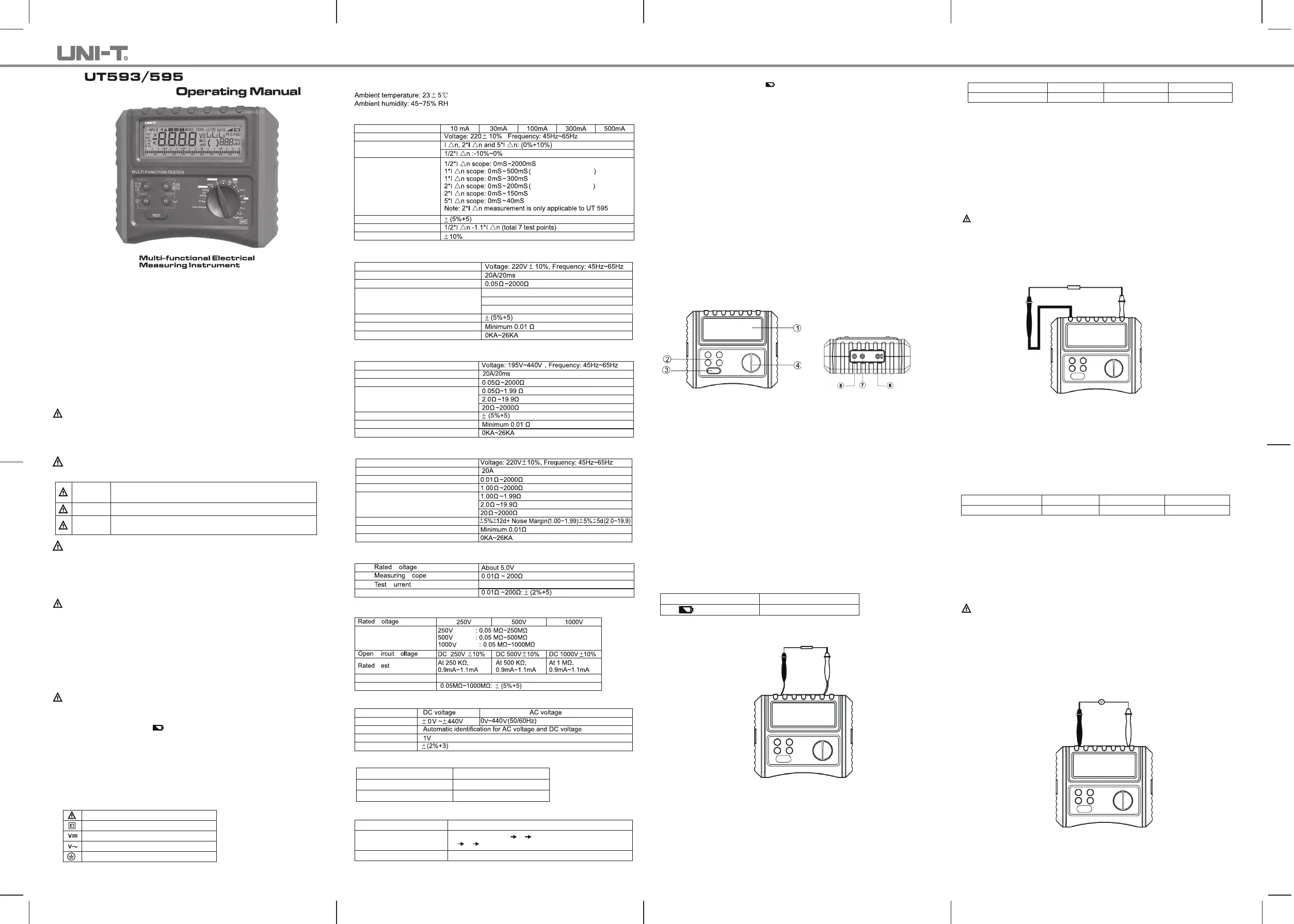
VIII. Testing for Continuity (See Figure 3)
Understanding F1-F4 Buttons:
F1 F2
F3
F4
Buzzer and backlight
Test lock
ZERO
Invalid
Figure 4
F1 F2
F3
F4
Buzzer and backlight
Test lock Invalid Invalid
Figure 5
I. Overview
UT593/UT595 is a multifunction digital safety testing instrument, designed with combin
-ation of large-scale integrated analog & digital circuits and micro-processor chip. It mai
-nly measures RCD, line/loop impedance, continuity, insulation resistance, DC and AC
voltage, phase sequence, featuring versatile functionality, higher accuracy, stable perfor
-mance and ease of use. The instrument is widely used to measure RCD, insulation and
earth connections for various equipments, and an ideal tool for testing, inspection and
maintenance badly needed for various electric devices and RCDs.
II. Safety Information
The Tester is designed, manufactured and tested according to IEC61010 safety standard.
The manual include safety information related to safe use of the Tester. Please strictly
follow the safety items and read the following instructions before use.
Warning
Warning
● Please read and understand the manual before using the Tester.
● Use the Tester as specified in the manual and keep it for future reference.
● Please note that misuse during tests might cause personal injury or damage to the
Tester.
on the Tester alerts users to use the Tester properly, please refer to the manual for
details.
Danger
Warning
Caution
Specifies conditions and actions that may cause severe or
fatal hazards.
Alerts users to avoid electric shock.
Specifies conditions and actions that may damage the Tester
or affect accurate measurement.
Danger
● Do not measure around any inflammables, sparkle may cause potential explosion.
● Do not operate the Tester if its surface is wet or the operator’s hands are wet.
● Do not touch conductive part of test leads during measurement.
● Do not measure with the battery cover opened.
● Do not touch the circuits under test when measuring insulation resistance and RCD.
● Stop using the Tester if any anomaly happens. E.g. the Tester is damaged or shows
exposed metal.
● Take extreme caution when working with voltages higher than 33Vrms, 46.7acrms or
70Vdc, for it may pose electric shock.
● The electric storage present in tested circuits must be released after finishing high-
resistance measurement.
● Do not replace the battery if the Tester is under wet status.
● Make sure all test leads are firmly secured to input terminals of the Tester.
● Turn off the Tester before opening the battery cover.
Caution
● If it is necessary to replace test leads or power adaptor, use only the same model
with same electrical specifications.
● When low battery indicator( ) shows, do not use the Tester. Take the batt
-ery if not used for a long time.
● Do not store or use the Tester around high-temperature, high humidity, flammables,
explosives and electromagnetic environments.
● Clean the Tester’s casing with soft cloth dampened with water or mild detergent. No
abrasives or solvents are allowed.
● Dry the Tester before storing it if it is wet.
III. Electrical Symbols
VI. Technical Specifications
Accuracy: ±(a% of reading + b digits), calibration per year.
1. RCD Test
Test Current
Operational Voltage
Test Current Accuracy
Trip Time
Trip Time Accuracy
Trip Current Range
Trip Current Accuracy
Select Timer Function
Select Timer Function
2.Loop Impedance Measurement
Operating Voltage (L - E)
Test Current& Time
Measuring Scope
Measuring Ranges
Accuracy
Resolution
Prospective Fault Current
3. Line Impedance Measurement
Operating Voltage (L - N)
Test Current& Time
Measuring Scope
Measuring Ranges
Accuracy
Resolution
Prospective Short Current
4. Non-Trip Loop Impedance Measurement
Operating Voltage (L - E)
Test Current
Display Range
Measuring Scope
Measuring Ranges
Accuracy
Resolution
Prospective Fault Current
5. Continuity Test
V
V
V
S
C
Accuracy
0.00~2.00Ω:>200mA
6. Insulation Resistance Measurement
Measuring Ranges
Short-Circuit Current
Accuracy
C
T
Range
Range
Range
<1.8mA
7. Voltage Measurement
Measuring Range
Special Function
Resolution
Accuracy
<10V: for reference only.
8. Frequency Measurement
9. Phase Rotation Test
● Display: LCD, display count: 9999
● Low Battery Indication: displays
● Over-Load Indication: “>over-limited value”(e.g.: >500MΩ)
● Auto Ranging
● Unit Display: Simultaneously display function and electrical units symbols
● Release Voltage Automatically
● Working Conditions: 0℃~40℃/Humidity:≤85%
● Storage Conditions: -20℃~60℃/Humidity:≤90%
● Current Consumption: around 50mA (at Max.1000V output voltage)(normally status
at 10mA)
● Safety: CATIII 300V, Pollution Degree 2 as per IEC61010
● Dimensions: 210mm(L)×175mm(W)×90mm(D)
● Weight: 1kg (including battery)
● Power: Alkaline battery 1.5V (AA) ×8pcs
● Accessories: Test leads, alkaline battery 1.5V (AA) ×8pcs, operating manual, carrying
bag
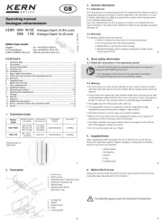
V. Tester Description (See Figure 1&2)
1. LCD Display
2. Function Buttons F1, F2, F3, F4
3. TEST Button
4. Rotary Switch
5. Input Terminal to Test Lead (Black)
6. Input Terminal to Test Lead (Red)
Or to specified test lead
7. Input Terminal to Test Lead (Green)
1. Phase Rotation: Detest Phase sequence
2. Volts: Measure Voltage/Frequency
3. 250V: Measure Insulation Resistance
4. 500V: Measure Insulation Resistance
5. 1000V: Measure Insulation Resistance
6.Ω: Continuity with Test Current up to 200mA;
7. OFF;
8. Loop/PSC/Zs/Ze:Measure Loop/Line Impedance, Prospective Fault current, Prospec
-tive Short Current.
9. Auto: Automatically Test RCD;
10.×1/2: Measure RCD Trip Time at ×1/2 Rated Current
11. ×1: Measure RCD Trip Time at ×1 Rated Current
12. ×2: Measure RCD Trip Time at ×2 Rated Current(for UT595 Only)
13. ×5: Measure RCD Trip Time at ×5 Rated Current
14. Ramp: Measure RCD Trip Current
If low battery indicator shows on the upper left part of LCD after turning on the Tester,
it indicates the battery falls low, please replace the battery time.
To test for continuity:
(1) Discharge totally the tested circuits and keep them completely separated from the
power supply before test.
(2) Insert red lead or specific TEST-marked test lead into red input terminal and black
test lead to black terminal.
(3) Connect red and black alligators or test probes to the circuit under test.
(4) Turn the rotary switch to Ω position, then press TEST button to begin. Refer to
Figure 3 for details.
F1: Long press F1 for about 2 seconds to turn on/off the backlight; short press to turn
on/off 20 Ω compare function and LCD will show buzzer indicator, the buzzer will
alarm if the measured resistance is <20Ω.
F2: Press to turn on/off TEST LOCKED function. When it is necessary to take a long
-time measurement, press F2 to enable the function, lock indicator shows on LCD,
you then just need to press TEST down once, release it and the Tester will take
measurements continuously.
Press TEST again to stop the measurements. To disable the function, press F2 again
or turn the rotary switch to other functions.
F3: Press to zero the test leads. First short-circuit two test leads, and then long press
F3 to reset the display to 0.00Ω, “ZERO” will show on LCD, indicating the operation
completes.
Caution:
● To ensure an accurate test, please perform the zeroing before test
● Do not test on live objects
● Before the test starts, the Tester will automatically display the voltage between two
input terminals if this voltage is >30V, and TEST button will be inhibited.
IX. Measuring Insulation Resistance (See Figure 4)
To measure insulation resistance:
(1) Discharge totally the tested circuits and keep them completely separated from the
power supply before test.
(2) Insert red lead or specific TEST-marked test lead into red input terminal and black
test lead to black terminal.
(3) Connect red and black alligators or test probes to the circuit under test.
(4) Turn the rotary switch to “Insulation” position and select proper test voltage, then
press TEST button to start.
Caution
● Make sure the test circuits are de-energized before measurement. Do not measure
any live electrical devices or lines.
● Before the test starts, the Tester will automatically display the voltage between two
input terminals if this voltage is >30V, and TEST button will be inhibited.
● Do not measure with the battery cover opened.
● Do not short-circuit two test leads under high- voltage output status or measure insu
-lation resistance after the high-voltage has already been output.
Understanding F1-F4 Buttons:
F1: Long press F1 for about 2 seconds to turn on/off the backlight; short press to turn
on/off 2 MΩ compare function. The buzzer will alarm if the measured resistance is
<2MΩ.
F2: Press to turn on/off TEST LOCKED function. When it is necessary to take a long-
time measurement, press F2 to enable the function, lock indicator shows on LCD,
you then just need to press TEST down once, release it and the Tester will take
measurements continuously.
Press TEST again to stop the measurements. To disable the function, press F2 again
or turn the rotary switch to other functions.
X. Measuring Voltage/Frequency (See Figure 5)
To measure voltage/frequency:
1) Set the rotary switch to Volts
Connect as shown in Figure 5: