PYMCORE SFX 750 GOLD SPECIFICATION
SPEC Label & Safety Instructions
Packaging content is as follows:
* XPG PYMCORE SFX Gold Modular Power Supply Unit
* SFX to ATX Adapter Bracket
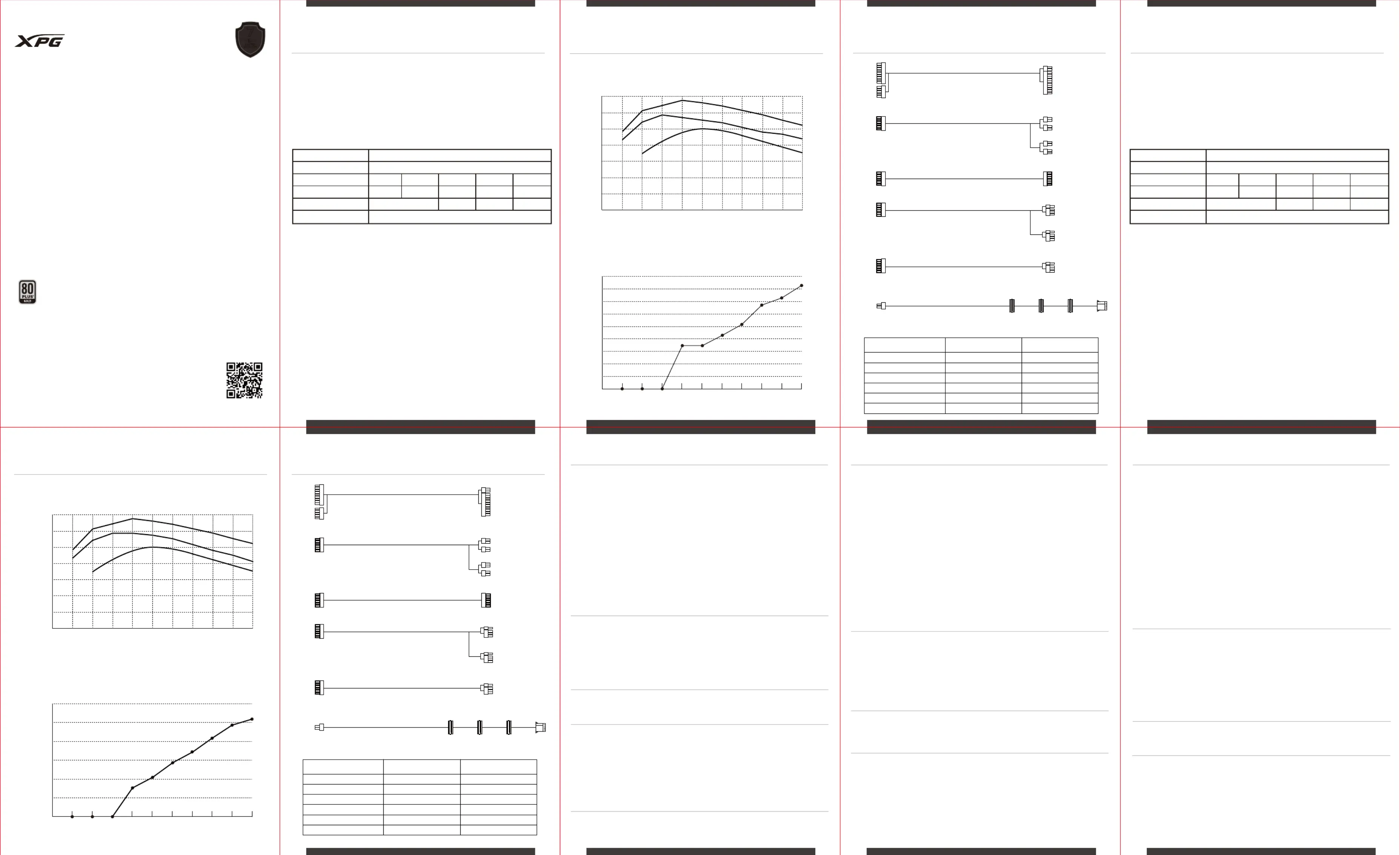
PYMCORE SFX 750 GOLD SPECIFICATION
PYMCORE SFX 750 GOLD DC cable listing
INSTALLING YOUR NEW PYMCORE POWER SUPPLY
1. Remove the power supply from its packaging.
2. Install the PSU into the case with the four screws provided.
3. Connect the 24pin ATX cable to the motherboard 24pin power socket.
4. Connect the EPS 12V 8 / 4+4pin cable to the CPU power socket.
5. Connect SATA power cables to any devices that may use 4-pin peripheral connectors, i.e. hard drives, solid state
6. Connect the corresponding PCI-E connector as instructed by your graphic card’s user manual, if your graphic
card requires additional PCI-E power.
Please note that the power supply utilizes a 6+2pin PCI-E connector that can be effectively used either as a single
8pin or a 6pin PCI-E connector.
To use it as a 6pin PCI-E connector, please detach the 2pin connector portion from the connector header.
7. Connect the peripheral/floppy disk 4pin connector for fans, pumps, legacy components and other
8. Connect the AC Power cord to both your power supply and to the wall.
Check all connections to ensure that every item is properly plugged in and turn the power switch of the power
supply to the ON position.
Make sure that your system is turned off and unplugged before you start installing it.
Disconnect the AC power cord from your old power supply if any.
1. Please make sure the AC main power cord is connected to your PC correctly and that your power outlet is properly
2. Please make sure the AC On/Off switch on the back panel of the power supply unit in the “I” (On) position.
3. Please make sure that the MB& CPU Power Socket & connectors are connected correctly on the motherboard.
4. If you still have problem turning on your PC, please contact ADATA Tech Support, Service Center or your local dealer.
If your system does not turn on after installing the power supply, please follow the
troubleshooting guide listed below:
ADATA Technology Co., Ltd. provides a 7 years warranty period for this product unless
regional laws and regulations state otherwise.
1. The warranty label is altered, damaged or missing.
2. Product serial number does not conform to our original system.
3. Product was purchased from an unauthorized agent.
4. Damage caused by natural calamity
5. Any abuse outside the intended product operation.
This limited warranty covers only repairs or replacements of products manufactured by
ADATA Technology Co. Ltd. and its authorized partners.
Please note that ADATA is responsible for providing free repairs except for the following
For frequently askeatd questions, additional information and service instruction please
visit our product page www.xpg.com
IHR NEUES PYMCORE-NETZTEIL INSTALLIEREN
1. Nehmen Sie das Netzteil aus seiner Verpackung.
2. Installieren Sie das Netzteil mit den vier mitgelieferten Schrauben im Gehäuse.
3. Verbinden Sie das 24-polige ATX-Kabel mit dem 24-poligen Stromanschluss des Motherboards.
4. Verbinden Sie das EPS-12V 8 / 4+4-Pin-Kabel mit dem CPU-Stromascnluss.
5. Verbinden Sie SATA-Kabel mit allen Geräten, die 4-polige Peripherieanschlüsse nutzen können, z. B. Festplatten,
Solid State Drives, optische Laufwerke.
6. Verbinden Sie den entsprechenden PCI-E-Anschluss entsprechend den Anweisungen der Bedienungsanleitung
Ihrer Grafikkarte, falls Ihre Grafikkarte zusätzliche PCI-E-Stromversorgung erfordert.
Bitte beachten Sie, dass das Netzteil einen 6+2-Pin-PCI-E-Anschluss nutzt, der effektiv als einzelner 8-poliger oder
6-poliger PCI-E-Anschluss genutzt werden kann.
Verwenden Sie ihn als 6-poligen PCI-E-Anschluss, indem Sie den 2-poligen Anschlussabschnitt von der Stiftleiste
7. Verbinden Sie den 4-poligen Anschluss von Peripherie/Diskettenlaufwerk für Lüfter, Pumpen, veraltete
Komponenten und andere Geräte/Adapter.
8. Verbinden Sie das Netzkabel mit Ihrem Netzteil und einer Steckdose.
Prüfen Sie alle Verbindungen, um sicherzustellen, dass alles richtig angeschlossen ist, drehen Sie dann den
Ein-/Ausschalter des Netzteils in die Ein-Position.
Stellen Sie sicher, dass Ihr System abgeschaltet und getrennt ist, bevor Sie mit der
Trennen Sie das Netzkabel von Ihrem alten Netzteil, falls vorhanden.
1. Vergewissern Sie sich, dass das Netzkabel richtig an Ihren PC angeschlossen ist und Ihre Steckdose funktioniert.
2. Prüfen Sie, ob der Ein-/Ausschalter an der Rückblende des Netzteils auf die Position „I“ (eingeschaltet) eingestellt
3. Vergewissern Sie sich, dass Stromanschlüsse von MB und CPU richtig am Motherboard angeschlossen sind.
4. Falls weiterhin Probleme beim Einschalten Ihres PCs auftreten, wenden Sie sich bitte an ADATAs technischen
Support, den Kundendienst oder Ihren örtlichen Händler.
Falls sich Ihr System nach Installation des Netzteils nicht einschaltet, befolgen Sie die
nachstehende Anleitung zur Fehlerbehebung:
ADATA Technology Co., Ltd. bietet eine 7-jährige Garantiedauer für dieses Produkt, sofern
nicht von regionalen Gesetzen und Vorschriften anders verlangt.
1. Das Garantieetikett wurde verändert, beschädigt oder fehlt.
2. Produktseriennummer stimmt nicht mit unserem ursprünglichen System überein.
3. Produkt wurde bei einem unautorisierten Händler erworben.
4. Schäden aufgrund von Naturkatastrophen.
5. Missbrauch bzw. Verwendung unter Nichtbeachtung der Bedienungsanweisungen.
Diese eingeschränkte Garantie deckt nur Reparaturen oder Auswechslungen von durch ADATA
Technology Co. Ltd. und seine autorisierten Partner ab.
Bitte beachten Sie, dass ADATA für die Bereitstellung kostenloser Reparaturen verantwortlich
ist, mit folgenden Ausnahmen:
INSTALLATION DE VOTRE NOUVELLE ALIMENTATION PYMCORE
1. Sortez le bloc d'alimentation de son emballage.
2. Installez le bloc d'alimentation dans le boîtier avec les quatre vis fournies.
3. Branchez le câble ATX 24 broches sur la prise d'alimentation 24 broches de la carte mère.
4. Connectez le câble EPS 12V 8 / 4+4 broches à la prise d'alimentation du CPU.
5. Raccordez les câbles d'alimentation SATA à tous les dispositifs pouvant utiliser des connecteurs périphériques à
4 broches, c'est-à-dire les disques durs, les SSD, les lecteurs optiques.
6. Branchez le connecteur PCI-E correspondant comme indiqué dans le manuel d'utilisation de votre carte
graphique, si votre carte graphique requiert une alimentation PCI-E dédiée.
Veuillez noter que l'alimentation utilise un connecteur PCI-E 6+2 broches qui peut servir effectivement de
connecteur PCI-E 8 broches ou 6 broches.
Pour l'utiliser comme connecteur PCI-E 6 broches, veuillez détacher la partie connecteur 2 broches de la tête du
7. Raccordez le connecteur périphérique / floppy (disquette) à 4 broches pour les ventilateurs, les pompes, les
composants anciens et les autres périphériques / adaptateurs.
8. Raccordez le cordon d'alimentation CA secteur à votre bloc d'alimentation et à la prise secteur.
Vérifiez tous les branchements pour vous assurer que chaque élément est correctement raccordé et mettez
l'interrupteur d'alimentation de l'alimentation en position MARCHE.
Assurez-vous que votre système est éteint et débranché avant de démarrer l’installation.
Débranchez le cordon d'alimentation CA secteur de votre ancien bloc d'alimentation, le
1. Veuillez vous assurer que le cordon d'alimentation secteur est correctement connecté à votre PC et que votre
prise de courant fournit correctement du courant.
2. Veuillez vous assurer que l'interrupteur secteur Marche / Arrêt situé sur le panneau arrière du bloc
d'alimentation est en position « I » (Marche).
3. Veuillez vous assurer que la prise et les connecteurs d'alimentation de la carte mère et du CPU sont
correctement raccordés à la carte mère.
4. Si vous avez toujours des problèmes pour allumer votre PC, veuillez contacter l’assistance technique ADATA, le
centre de service ou votre revendeur local.
1. L'étiquette de garantie a été altérée, endommagée ou enlevée.
2. Le numéro de série du produit n'est pas conforme à notre système original.
3. Le produit a été acheté auprès d'un agent non autorisé.
4. Les dommages causés par une catastrophe naturelle
5. Tout abus en dehors de l'utilisation prévue du produit.
Si votre système ne s'allume pas après avoir installé l'alimentation, veuillez suivre le guide
de dépannage ci-dessous :
ADATA Technology Co. Ltd. offre une garantie limitée de trois (7) ans pour ce produit, à
moins que les lois et règlements régionaux ne stipulent le contraire.
Cette garantie limitée couvre uniquement les réparations ou les remplacements des
produits fabriqués par ADATA Technology Co. Ltd. et ses partenaires autorisés.
Veuillez noter qu'ADATA est responsable de fournir des réparations gratuites, sauf pour
PYMCORE SFX 850 GOLD SPECIFICATION
SPEC Label & Safety Instructions
Packaging content is as follows:
* XPG PYMCORE SFX Gold Modular Power Supply Unit
* SFX to ATX Adapter Bracket
PYMCORE SFX 850 GOLD SPECIFICATION PYMCORE SFX 850 GOLD DC cable listing
Power Supply Efficiency / 25°C
40% 60% 80% 100%20% 30% 50% 70% 90%10%
10% 30% 40% 50% 60% 70% 80% 90% Full20%
Connector Quantity Cable Quantity
Power Supply Efficiency / 25°C
40% 60% 80% 100%20% 30% 50% 70% 90%10%
10% 30% 40% 50% 60% 70% 80% 90% Full20%
Connector Quantity Cable Quantity