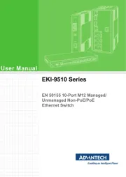
Advantech EKI-9508E-MPH-AE Manual

Advantech Skifte EKI-9508E-MPH-AE

Læs gratis den danske manual til Advantech EKI-9508E-MPH-AE (171 sider) i kategorien Skifte. Denne vejledning er vurderet som hjælpsom af 26 personer og har en gennemsnitlig bedømmelse på 4.7 stjerner ud af 13.5 anmeldelser. Har du et spørgsmål om Advantech EKI-9508E-MPH-AE, eller vil du spørge andre brugere om produktet?

Side 1/171
User Manual
EKI-9508 Series
EN 50155 8-Port M12 Managed/
Unmanaged Non-PoE/PoE
Ethernet Switch
EKI-9508 Series User Manual ii
Copyright
The documentation and the software included with this product are copyrighted 2019
by Advantech Co., Ltd. All rights are reserved. Advantech Co., Ltd. reserves the right
to make improvements in the products described in this manual at any time without
notice. No part of this manual may be reproduced, copied, translated or transmitted
in any form or by any means without the prior written permission of Advantech Co.,
Ltd. Information provided in this manual is intended to be accurate and reliable. How-
ever, Advantech Co., Ltd. assumes no responsibility for its use, nor for any infringe-
ments of the rights of third parties, which may result from its use.
Acknowledgements
Intel and Pentium are trademarks of Intel Corporation.
Microsoft Windows and MS-DOS are registered trademarks of Microsoft Corp.
All other product names or trademarks are properties of their respective owners.
Product Warranty (5 years)
Advantech warrants to you, the original purchaser, that each of its products will be
free from defects in materials and workmanship for five years from the date of pur-
chase.
This warranty does not apply to any products which have been repaired or altered by
persons other than repair personnel authorized by Advantech, or which have been
subject to misuse, abuse, accident or improper installation. Advantech assumes no
liability under the terms of this warranty as a consequence of such events.
Because of Advantech’s high quality-control standards and rigorous testing, most of
our customers never need to use our repair service. If an Advantech product is defec-
tive, it will be repaired or replaced at no charge during the warranty period. For out of-
warranty repairs, you will be billed according to the cost of replacement materials,
service time and freight. Please consult your dealer for more details.
If you think you have a defective product, follow these steps:
1. Collect all the information about the problem encountered. (For example, CPU
speed, Advantech products used, other hardware and software used, etc.) Note
anything abnormal and list any on screen messages you get when the problem
occurs.
2. Call your dealer and describe the problem. Please have your manual, product,
and any helpful information readily available.
3. If your product is diagnosed as defective, obtain an RMA (return merchandize
authorization) number from your dealer. This allows us to process your return
more quickly.
4. Carefully pack the defective product, a fully-completed Repair and Replacement
Order Card and a photocopy proof of purchase date (such as your sales receipt)
in a shippable container. A product returned without proof of the purchase date
is not eligible for warranty service.
5. Write the RMA number visibly on the outside of the package and ship it prepaid
to your dealer.
Part No. XXXXXXXXXX Edition 1
Printed in Taiwan September 2019
iii EKI-9508 Series User Manual
Declaration of Conformity
CE
This product has passed the CE test for environmental specifications. Test conditions
for passing included the equipment being operated within an industrial enclosure. In
order to protect the product from being damaged by ESD (Electrostatic Discharge)
and EMI leakage, we strongly recommend the use of CE-compliant industrial enclo-
sure products.
FCC Class A
Note: This equipment has been tested and found to comply with the limits for a Class
A digital device, pursuant to part 15 of the FCC Rules. These limits are designed to
provide reasonable protection against harmful interference when the equipment is
operated in a commercial environment. This equipment generates, uses, and can
radiate radio frequency energy and, if not installed and used in accordance with the
instruction manual, may cause harmful interference to radio communications. Opera-
tion of this equipment in a residential area is likely to cause harmful interference in
which case the user will be required to correct the interference at his own expense.
Technical Support and Assistance
1. Visit the Advantech web site at www.advantech.com/support where you can find
the latest information about the product.
2. Contact your distributor, sales representative, or Advantech's customer service
center for technical support if you need additional assistance. Please have the
following information ready before you call:
Product name and serial number
Description of your peripheral attachments
Description of your software (operating system, version, application software,
etc.)
A complete description of the problem
The exact wording of any error messages
EKI-9508 Series User Manual iv
Warnings, Cautions and Notes
Document Feedback
To assist us in making improvements to this manual, we would welcome comments
and constructive criticism. Please send all such - in writing to: support@advan-
tech.com
Packing List
Before setting up the system, check that the items listed below are included and in
good condition. If any item does not accord with the table, please contact your dealer
immediately.
1 x EN 50155 8-Port M12 Managed/Unmanaged Non-PoE/PoE Ethernet Switch
Warning! Warnings indicate conditions, which if not observed, can cause personal
injury!
Caution! Cautions are included to help you avoid damaging hardware or losing
data. e.g.
There is a danger of a new battery exploding if it is incorrectly installed.
Do not attempt to recharge, force open, or heat the battery. Replace the
battery only with the same or equivalent type recommended by the man-
ufacturer. Discard used batteries according to the manufacturer's
instructions.
Note! Notes provide optional additional information.
EKI-9508 Series User Manual vi
Wichtige Sicherheishinweise
Bitte lesen sie Sich diese Hinweise sorgfältig durch.
Heben Sie diese Anleitung für den späteren Gebrauch auf.
Vor jedem Reinigen ist das Gerät vom Stromnetz zu trennen. Verwenden Sie
Keine Flüssig-oder Aerosolreiniger. Am besten dient ein angefeuchtetes Tuch
zur Reinigung.
Die NetzanschluBsteckdose soll nahe dem Gerät angebracht und leicht zugän-
glich sein.
Das Gerät ist vor Feuchtigkeit zu schützen.
Bei der Aufstellung des Gerätes ist auf sicheren Stand zu achten. Ein Kippen
oder Fallen könnte Verletzungen hervorrufen.
Die Belüftungsöffnungen dienen zur Luftzirkulation die das Gerät vor überhit-
zung schützt. Sorgen Sie dafür, daB diese Öffnungen nicht abgedeckt werden.
Beachten Sie beim. AnschluB an das Stromnetz die AnschluBwerte.
Verlegen Sie die NetzanschluBleitung so, daB niemand daber fallen kann. Es
sollte auch nichts auf der Leitung abgestellt werden.
Alle Hinweise und Warnungen die sich am Geräten befinden sind zu beachten.
Wird das Gerät über einen längeren Zeitraum nicht benutzt, sollten Sie es vom
Stromnetz trennen. Somit wird im Falle einer Überspannung eine Beschädigung
vermieden.
Durch die Lüftungsöffnungen dürfen niemals Gegenstände oder Flüssigkeiten in
das Gerät gelangen. Dies könnte einen Brand bzw. elektrischen Schlag aus-
lösen.
Öffnen Sie niemals das Gerät. Das Gerät darf aus Gründen der elektrischen
Sicherheit nur von authorisiertem Servicepersonal geöffnet werden.
Wenn folgende Situationen auftreten ist das Gerät vom Stromnetz zu trennen
und von einer qualifizierten Servicestelle zu überprüfen:
Netzkabel oder Netzstecker sind beschädigt.
Flüssigkeit ist in das Gerät eingedrungen.
Das Gerät war Feuchtigkeit ausgesetzt.
Wenn das Gerät nicht der Bedienungsanleitung entsprechend funktioniert
oder Sie mit Hilfe dieser Anleitung keine Verbesserung erzielen.
Das Gerät ist gefallen und/oder das Gehäuse ist beschädigt.
Wenn das Gerät deutliche Anzeichen eines Defektes aufweist.
Der arbeitsplatzbezogene Schalldruckpegel nach DIN 45 635 Teil 1000 beträgt
70dB(A) oder weiger.
Haftungsausschluss: Die Bedienungsanleitungen wurden entsprechend der
IEC-704-1 erstellt. Advantech lehnt jegliche Verantwortung für die Richtigkeit
der in diesem Zusammenhang getätigten Aussagen ab.
vii EKI-9508 Series User Manual
Safety Precaution - Static Electricity
Static electricity can cause bodily harm or damage electronic devices. To avoid dam-
age, keep static-sensitive devices in the static-protective packaging until the installa-
tion period. The following guidelines are also recommended:
Wear a grounded wrist or ankle strap and use gloves to prevent direct contact to
the device before servicing the device. Avoid nylon gloves or work clothes,
which tend to build up a charge.
Always disconnect the power from the device before servicing it.
Before plugging a cable into any port, discharge the voltage stored on the cable
by touching the electrical contacts to the ground surface.
ix EKI-9508 Series User Manual
4.3.6 IGMP Statistics ........................................................................... 37
4.3.7 MLD Statistics ............................................................................. 38
4.4 System .................................................................................................... 39
4.4.1 IP Settings................................................................................... 39
4.4.2 IPv6 Settings............................................................................... 40
4.4.3 DHCP Client Option 82 ............................................................... 41
4.4.4 DHCP Auto Provision.................................................................. 42
4.4.5 Management VLAN..................................................................... 42
4.4.6 System Time............................................................................... 43
4.4.7 Network Port ............................................................................... 44
4.5 L2 Switching............................................................................................ 45
4.5.1 Port Configuration....................................................................... 45
4.5.2 Port Mirror ................................................................................... 46
4.5.3 Link Aggregation ......................................................................... 47
4.5.4 802.1Q VLAN.............................................................................. 50
4.5.5 Q-in-Q ......................................................................................... 53
4.5.6 GARP.......................................................................................... 55
4.5.7 802.3az EEE ............................................................................... 57
4.5.8 Multicast...................................................................................... 57
4.5.9 Jumbo Frame.............................................................................. 62
4.5.10 Spanning Tree ............................................................................ 63
4.5.11 X-Ring Elite ................................................................................. 68
4.5.12 X-Ring Pro .................................................................................. 69
4.5.13 Loopback Detection .................................................................... 72
4.5.14 ERPS .......................................................................................... 73
4.6 MAC Address Table ................................................................................ 75
4.6.1 Static MAC .................................................................................. 75
4.6.2 MAC Aging Time......................................................................... 75
4.6.3 Dynamic Forwarding Table ......................................................... 76
4.7 Security ................................................................................................... 77
4.7.1 Storm Control.............................................................................. 77
4.7.2 Port Security ............................................................................... 79
4.7.3 Protected Ports ........................................................................... 79
4.7.4 DoS Prevention........................................................................... 80
4.7.5 Applications................................................................................. 82
4.7.6 802.1x ......................................................................................... 85
4.7.7 IP Security................................................................................... 86
4.7.8 Security Login ............................................................................. 87
4.7.9 Access Control List ..................................................................... 90
4.7.10 IP Source Guard ......................................................................... 92
4.7.11 DHCP Snooping.......................................................................... 93
4.7.12 ARP Spoofing ............................................................................. 94
4.8 QoS ......................................................................................................... 95
4.8.1 General ....................................................................................... 95
4.8.2 QoS Basic Mode ....................................................................... 101
4.8.3 Rate Limit.................................................................................. 102
4.8.4 Bandwidth Guarantee ............................................................... 104
4.9 Management ......................................................................................... 106
4.9.1 LLDP ......................................................................................... 106
4.9.2 SNMP........................................................................................ 109
4.9.3 Power Over Ethernet ................................................................ 112
4.9.4 TCP Modbus Settings ............................................................... 114
4.9.5 DHCP Server ............................................................................ 115
4.9.6 SMTP Client.............................................................................. 121
4.9.7 RMON ....................................................................................... 123
4.9.8 NTP Server ............................................................................... 127
4.10 Diagnostics............................................................................................ 128
4.10.1 Cable Diagnostics ..................................................................... 128
4.10.2 Ping Test................................................................................... 129
EKI-9508 Series User Manual x
4.10.3 IPv6 Ping Test .......................................................................... 130
4.10.4 System Log............................................................................... 132
4.10.5 LED Indication .......................................................................... 134
4.11 Tools ..................................................................................................... 135
4.11.1 IXM ........................................................................................... 135
4.11.2 Backup Manager....................................................................... 136
4.11.3 Upgrade Manager..................................................................... 137
4.11.4 Dual Image ............................................................................... 138
4.11.5 Save Configuration ................................................................... 138
4.11.6 User Account ............................................................................ 138
4.11.7 N-Key....................................................................................... 139
4.11.8 Reset System ........................................................................... 139
4.11.9 Reboot Device .......................................................................... 139
4.12 Modbus/TCP Mapping .......................................................................... 140
4.12.1 Modbus/TCP Mapping Table .................................................... 140
xi EKI-9508 Series User Manual
List of Figures
Figure 1.1 Front View ..................................................................................................................... 4
Figure 1.2 Front View ..................................................................................................................... 5
Figure 1.3 Front View ..................................................................................................................... 5
Figure 1.4 Front View ..................................................................................................................... 6
Figure 1.5 Front View ..................................................................................................................... 7
Figure 1.6 Front View ..................................................................................................................... 7
Figure 1.7 Front View ..................................................................................................................... 8
Figure 1.8 Front View ..................................................................................................................... 9
Figure 1.9 System LED Panel ...................................................................................................... 10
Figure 1.10 EKI-9508E-H/EKI-9508E-L Dimensions ...................................................................... 11
Figure 1.11 EKI-9508E-MH/EKI-9508E-ML Dimensions ................................................................ 11
Figure 1.12 EKI-9508E-MPH/EKI-9508E-MPL Dimensions ........................................................... 12
Figure 1.13 EKI-9508E-PH/EKI-9508E-PL Dimensions ................................................................. 12
Figure 1.14 EKI-9508G-H/EKI-9508G-L Dimensions ..................................................................... 13
Figure 1.15 EKI-9508G-MH/EKI-9508G-ML Dimensions ............................................................... 13
Figure 1.16 EKI-9508G-MPH/EKI-9508G-MPL Dimensions .......................................................... 14
Figure 1.17 EKI-9508G-PH/EKI-9508G-PL Dimensions ................................................................ 14
Figure 2.1 Securing Wall Mounting Screws.................................................................................. 17
Figure 2.2 Switch Installation........................................................................................................ 17
Figure 2.3 Power Wiring for EKI-9508 Series............................................................................... 18
Figure 2.4 Grounding Connection, Chassis Left Side View.......................................................... 20
Figure 2.5 Installing the Power Cable........................................................................................... 21
Figure 2.6 Standard M12 4-Pin Female DC Power Input Connector............................................ 21
Figure 2.7 M12 D-Coded Connector Pin Assignment................................................................... 22
Figure 2.8 M12 X-Coded Connector Pin Assignment................................................................... 22
Figure 2.9 M12 A-Coded Connector Pin Assignment................................................................... 23
Figure 4.1 Login Screen ............................................................................................................... 31
Figure 4.2 Changing a Default Password ..................................................................................... 32
Figure 4.3 Monitoring > Device Information.................................................................................. 32
Figure 4.4 Monitoring > Logging Message ................................................................................... 33
Figure 4.5 Monitoring > Port Monitoring > Port Statistics ............................................................. 34
Figure 4.6 Monitoring > Port Monitoring > Port Utilization ............................................................ 35
Figure 4.7 Monitoring > LLDP Statistics ....................................................................................... 36
Figure 4.8 Monitoring > IGMP Statistics ....................................................................................... 37
Figure 4.9 Monitoring > MLD Statistics ......................................................................................... 38
Figure 4.10 System > IP Settings ................................................................................................... 39
Figure 4.11 System > IPv6 Settings ............................................................................................... 40
Figure 4.12 System > DHCP Client Option 82................................................................................ 41
Figure 4.13 System > DHCP Auto Provision .................................................................................. 42
Figure 4.14 System > Management VLAN ..................................................................................... 42
Figure 4.15 System > System Time................................................................................................ 43
Figure 4.16 System > Network Port................................................................................................ 44
Figure 4.17 L2 Switching > Port Configuration ............................................................................... 45
Figure 4.18 L2 Switching > Port Mirror ........................................................................................... 46
Figure 4.19 L2 Switching > Link Aggregation > Load Balance ....................................................... 47
Figure 4.20 L2 Switching > Link Aggregation > LAG Management................................................ 47
Figure 4.21 L2 Switching > Link Aggregation > LAG Port Settings ................................................ 48
Figure 4.22 L2 Switching > Link Aggregation > LACP Priority Settings ......................................... 48
Figure 4.23 L2 Switching > Link Aggregation > LACP Port Settings .............................................. 49
Figure 4.24 L2 Switching > 802.1Q VLAN > VLAN Management .................................................. 50
Figure 4.25 L2 Switching > 802.1Q VLAN > PVID Settings ........................................................... 51
Figure 4.26 L2 Switching > 802.1Q VLAN > Port to VLAN............................................................. 52
Figure 4.27 L2 Switching > Q-in-Q > Global Settings..................................................................... 53
Figure 4.28 L2 Switching > Q-in-Q > Port Settings......................................................................... 54
Figure 4.29 L2 Switching > GARP > GARP Settings...................................................................... 55
Figure 4.30 L2 Switching > GARP > GVRP Settings...................................................................... 56
EKI-9508 Series User Manual xii
Figure 4.31 L2 Switching > GARP > GMRP Settings..................................................................... 56
Figure 4.32 L2 Switching > 802.3az EEE....................................................................................... 57
Figure 4.33 L2 Switching > Multicast > Multicast Filtering.............................................................. 57
Figure 4.34 L2 Switching > Multicast > IGMP Snooping > IGMP Settings ..................................... 58
Figure 4.35 L2 Switching > Multicast > IGMP Snooping > IGMP Querier ...................................... 59
Figure 4.36 L2 Switching > Multicast > IGMP Snooping > IGMP Static Groups ............................ 59
Figure 4.37 L2 Switching > Multicast > MLD Snooping > MLD Settings ........................................ 60
Figure 4.38 L2 Switching > Multicast > MLD Snooping > MLD Querier ......................................... 61
Figure 4.39 L2 Switching > Multicast > MLD Snooping > MLD Static Group ................................. 61
Figure 4.40 L2 Switching > Jumbo Frame...................................................................................... 62
Figure 4.41 L2 Switching > Spanning Tree > STP Global Settings................................................ 63
Figure 4.42 L2 Switching > Spanning Tree > STP Port Settings.................................................... 64
Figure 4.43 L2 Switching > Spanning Tree > STP Bridge Settings................................................ 65
Figure 4.44 L2 Switching > Spanning Tree > STP Port Advanced Settings................................... 66
Figure 4.45 L2 Switching > Spanning Tree > MST Config Identification ........................................ 66
Figure 4.46 L2 Switching > Spanning Tree > MST Instance ID Settings ....................................... 67
Figure 4.47 L2 Switching > Spanning Tree > MST Instance Priority Settings................................ 67
Figure 4.48 L2 Switching > X-Ring Elite > X-Ring Elite Settings.................................................... 68
Figure 4.49 L2 Switching > X-Ring Elite > X-Ring Elite Groups ..................................................... 69
Figure 4.50 L2 Switching > X-Ring Pro > X-Ring Pro Settings....................................................... 69
Figure 4.51 L2 Switching > X-Ring Pro > X-Ring Pro Groups > X-Ring Pro Groups Settings ....... 70
Figure 4.52 L2 Switching > X-Ring Pro > X-Ring Pro Groups > Chain Settings ............................ 70
Figure 4.53 L2 Switching > X-Ring Pro > X-Ring Pro Groups > Couple Setting ............................ 70
Figure 4.54 L2 Switching > X-Ring Pro > X-Ring Pro Groups > Pair Settings ............................... 71
Figure 4.55 L2 Switching > X-Ring Pro > X-Ring Pro Groups > RPair Settings............................. 71
Figure 4.56 L2 Switching > Loopback Detection > Global Settings................................................ 72
Figure 4.57 L2 Switching > Loopback Detection > Port Settings ................................................... 73
Figure 4.58 L2 Switching > ERPS > ERPS Settings ...................................................................... 73
Figure 4.59 L2 Switching > ERPS > ERPS Groups ....................................................................... 74
Figure 4.60 MAC Address Table > Static MAC .............................................................................. 75
Figure 4.61 MAC Address Table > MAC Aging Time..................................................................... 75
Figure 4.62 MAC Address Table > Dynamic Forwarding Table ..................................................... 76
Figure 4.63 Security > Storm Control > Global Settings................................................................. 77
Figure 4.64 Security > Storm Control > Port Settings .................................................................... 78
Figure 4.65 Security > Port Security............................................................................................... 79
Figure 4.66 Security > Protected Ports........................................................................................... 79
Figure 4.67 Security > DoS Prevention > DoS Global Settings...................................................... 80
Figure 4.68 Security > DoS Prevention > DoS Port Settings ......................................................... 82
Figure 4.69 Security > Applications > TELNET .............................................................................. 82
Figure 4.70 Security > Applications > SSH .................................................................................... 83
Figure 4.71 Security > Applications > HTTP .................................................................................. 83
Figure 4.72 Security > Applications > HTTPS ................................................................................ 84
Figure 4.73 Security > 802.1x > 802.1x Global Settings ................................................................ 85
Figure 4.74 Security > 802.1x > 802.1x Port Configuration............................................................ 86
Figure 4.75 Security > IP Security > Global Settings ..................................................................... 86
Figure 4.76 Security > IP Security > Entry Settings ....................................................................... 87
Figure 4.77 Security > Security Login > Global Settings > Global Settings.................................... 87
Figure 4.78 Security > Security Login > Global Settings > RADIUS Settings ................................ 88
Figure 4.79 Security > Security Login > Global Settings > TACACS Settings ............................... 88
Figure 4.80 Security > Security Login > Access Control Settings > Security Login
Type Settings .............................................................................................................. 89
Figure 4.81 Security > Security Login > Access Control Settings > Security Login
Type Settings .............................................................................................................. 89
Figure 4.82 Security > Access Control List > MAC ACL > Entry Settings ...................................... 90
Figure 4.83 Security > Access Control List > IP ACL > Entry Settings........................................... 91
Figure 4.84 Security > IP Source Guard > Global Settings ............................................................ 92
Figure 4.85 Security > IP Source Guard > Entry Settings .............................................................. 92
Figure 4.86 Security > DHCP Snooping > Global Settings > DHCP Snooping State Settings....... 93
Figure 4.87 Security > DHCP Snooping > Global Settings > DHCP Snooping Port Settings ........ 93
xiii EKI-9508 Series User Manual
Figure 4.88 Security > DHCP Snooping > Global Settings > DHCP Snooping Binding
Port Settings ................................................................................................................ 94
Figure 4.89 Security > ARP Spoofing............................................................................................. 94
Figure 4.90 QoS > General > QoS Properties ................................................................................ 95
Figure 4.91 QoS > General > QoS Settings ................................................................................... 96
Figure 4.92 QoS > General > QoS Scheduling .............................................................................. 97
Figure 4.93 QoS > General > CoS Mapping................................................................................... 98
Figure 4.94 QoS > General > DSCP Mapping................................................................................ 99
Figure 4.95 QoS > General > IP Precedence Mapping ................................................................ 100
Figure 4.96 QoS > QoS Basic Mode > Global Settings................................................................ 101
Figure 4.97 QoS > QoS Basic Mode > Port Settings.................................................................... 101
Figure 4.98 QoS > Rate Limit > Ingress Bandwidth Control ......................................................... 102
Figure 4.99 QoS > Rate Limit > Egress Bandwidth Control ......................................................... 102
Figure 4.100 QoS > Rate Limit > Egress Queue ............................................................................ 103
Figure 4.101 QoS > Bandwidth Guarantee > Global Settings ........................................................ 104
Figure 4.102 QoS > Bandwidth Guarantee > Utilzation.................................................................. 105
Figure 4.103 Management > LLDP > LLDP System Settings ........................................................ 106
Figure 4.104 Management > LLDP > LLDP Port Settings > LLDP Port Configuration................... 107
Figure 4.105 Management > LLDP > LLDP Port Settings > Optional TLVs Selection ................... 107
Figure 4.106 Management > LLDP > LLDP Port Settings > VLAN Name TLV VLAN Selection .... 108
Figure 4.107 Management > LLDP > LLDP Remote Device Info................................................... 108
Figure 4.108 Management > SNMP > SNMP Settings................................................................... 109
Figure 4.109 Management > SNMP > SNMP Community ............................................................. 109
Figure 4.110 Management > SNMP > SNMPv3 EngineID ............................................................. 110
Figure 4.111 Management > SNMP > SNMPv3 Settings............................................................... 110
Figure 4.112 Management > SNMP > SNMP Trap ........................................................................ 111
Figure 4.113 Management > Power Over Ethernet > PoE System Settings .................................. 112
Figure 4.114 Management > Power Over Ethernet > PoE Port Settings ....................................... 113
Figure 4.115 Management > TCP Modbus Settings > TCP Modbus Settings ............................... 114
Figure 4.116 Management > DHCP Server > Status Settings ....................................................... 115
Figure 4.117 Management > DHCP Server > Global Settings ....................................................... 116
Figure 4.118 Management > DHCP Server > Port Settings ........................................................... 117
Figure 4.119 Management > DHCP Server > VLAN Settings ........................................................ 118
Figure 4.120 Management > DHCP Server > Option 82 Settings .................................................. 119
Figure 4.121 Management > DHCP Server > Client MAC Settings ............................................... 120
Figure 4.122 Management > SMTP Client > Global Settings......................................................... 121
Figure 4.123 Management > SMTP Client > Profile Settings > Profile Settings............................. 121
Figure 4.124 Management > SMTP Client > Profile Settings > Profile Target Mail Settings.......... 122
Figure 4.125 Management > SMTP Client > Sending Message .................................................... 122
Figure 4.126 Management > RMON > Rmon Statistics ................................................................. 123
Figure 4.127 Management > RMON > RMON History ................................................................... 124
Figure 4.128 Management > RMON > Rmon Alarm ...................................................................... 125
Figure 4.129 Management > RMON > RMON Event ..................................................................... 126
Figure 4.130 Management > NTP Server....................................................................................... 127
Figure 4.131 Diagnostics > Cable Diagnostics ............................................................................... 128
Figure 4.132 Diagnostics > Ping Test............................................................................................. 129
Figure 4.133 Diagnostics > IPv6 Ping Test..................................................................................... 130
Figure 4.134 Diagnostics > System Log > Logging Service ........................................................... 132
Figure 4.135 Diagnostics > System Log > Local Logging .............................................................. 132
Figure 4.136 Diagnostics > System Log > System Log Server ...................................................... 133
Figure 4.137 Diagnostics > LED Indication..................................................................................... 134
Figure 4.138 Tools > IXM ............................................................................................................... 135
Figure 4.139 Tools > Backup Manager........................................................................................... 136
Figure 4.140 Tools > Upgrade Manager......................................................................................... 137
Figure 4.141 Tools > Dual Image ................................................................................................... 138
Figure 4.142 Tools > User Account ................................................................................................ 138
Figure 4.143 Tools > N-Key............................................................................................................ 139
Chapter 1
1Product Overview
2 EKI-9508 Series User Manual
1.1 Specifications
Specifications Description
Interface I/O Port EKI-9508E-H/EKI-9508E-L: 8 x 10/100BASE-T
M12 D-coded
EKI-9508E-MH/EKI-9508E-ML: 8 x 10/
100BASE-T M12 D-coded
EKI-9508E-MPH/EKI-9508E-MPL: 8 x 10/
100BASE-T M12 D-coded
EKI-9508E-PH/EKI-9508E-PL: 8 x 10/
100BASE-T M12 D-coded
EKI-9508G-H/EKI-9508G-L: 8 x 10/100/1000
BASE-T M12 X-coded
EKI-9508G-MH/EKI-9508G-ML: 8 x 10/100/
1000 BASE-T M12 X-coded
EKI-9508G-MPH/EKI-9508G-MPL:8 x 10/100/
1000 BASE-T M12 X-Coded
EKI-9508G-PH/EKI-9508G-PL: 8 x 10/100/1000
BASE-T M12 X-coded
Console Port M12 A-coded (only for EKI-9508E-MH/
EKI-9508E-ML, EKI-9508E-MPH/EKI-9508E-MPL,
EKI-9508G-MH/EKI-9508G-ML and
EKI-9508G-MPH/EKI-9508G-MPL)
Power Connector M12 A-coded
Physical Enclosure Metal shell
Protection Class IP40
Installation Wall mount
Dimensions
(W x H x D)
122.5 x 179.4 x 71.8 mm (4.82” x 7.06” x 2.83”)
Weight 1.3 kg (2.87 lbs)
LED Display System LED SYS, PWR1, PWR2, R.M. (R.M. is only for
EKI-9508E-MH/EKI-9508E-ML, EKI-9508E-MPH/
EKI-9508E-MPL, EKI-9508G-MH/EKI-9508G-ML and
EKI-9508G-MPH/EKI-9508G-MPL)
Port LED Data, PoE (only for EKI-9508E-MPH/
EKI-9508E-MPL, EKI-9508E-PH/EKI-9508E-PL,
EKI-9508G-MPH/EKI-9508G-MPL and
EKI-9508G-PH/EKI-9508G-PL)
Environment Operating
Temperature
-40°C ~ 70°C (-40°F ~ 158°F)
Storage
Temperature
-40°C ~ 85°C (-40°F ~ 185°F)
Ambient Relative
Humidity
5 ~ 95% (non-condensing)
Switch Properties MAC Address 8K
Jumbo Frame 9 KB
EKI-9508 Series User Manual 3
Power Power
Consumption
~ 5 W (System)
PoE Power
Budget
EKI-9508E-MPH: 90 Watts
EKI-9508E-MPL: 60 Watts
EKI-9508E-PH: 90 Watts
EKI-9508E-PL: 60 Watts
EKI-9508G-MPH: 90 Watts
EKI-9508G-MPL: 60 Watts
EKI-9508G-PH: 90 Watts
EKI-9508G-PL: 60 Watts
Power Input EKI-9508E-H: 72/96/110 VDC
EKI-9508E-L: 24/48 VDC
EKI-9508E-MH: 72/96/110 VDC
EKI-9508E-ML: 24/48 VDC
EKI-9508E-MPH: 72/96/110 VDC
EKI-9508E-MPL: 24/48 VDC
EKI-9508E-PH: 72/96/110 VDC
EKI-9508E-PL: 24/48 VDC
EKI-9508G-H: 72/96/110 VDC
EKI-9508G-L: 24/48 VDC
EKI-9508G-MH: 72/96/110 VDC
EKI-9508G-ML: 24/48 VDC
EKI-9508G-MPH: 72/96/110 VDC
EKI-9508G-MPL: 24/48 VDC
EKI-9508G-PH: 72/96/110 VDC
EKI-9508G-PL: 24/48 VDC
Operating Voltage EKI-9508E-H: 50.4 ~ 137.5 VDC
EKI-9508E-L: 16.8 ~ 60 VDC
EKI-9508E-MH: 50.4 ~ 137.5 VDC
EKI-9508E-ML: 16.8 ~ 60 VDC
EKI-9508E-MPH: 50.4 ~ 137.5 VDC
EKI-9508E-MPL: 16.8 ~ 60 VDC
EKI-9508E-PH:50.4 ~ 137.5 VDC
EKI-9508E-PL: 16.8 ~ 60 VDC
EKI-9508G-H: 50.4 ~ 137.5 VDC
EKI-9508G-L: 16.8 ~ 60 VDC
EKI-9508G-MH: 50.4 ~ 137.5 VDC
EKI-9508G-ML: 16.8 ~ 60 VDC
EKI-9508G-MPH: 50.4 ~ 137.5 VDC
EKI-9508G-MPL: 16.8 ~ 60 VDC
EKI-9508G-PH:50.4 ~ 137.5 VDC
EKI-9508G-PL: 16.8 ~ 60 VDC
Dual inputs supports overload current protection and
reverse polarity protection
Specifications Description
4 EKI-9508 Series User Manual
1.2 Hardware Views
1.2.1 Front View
1.2.1.1 EKI-9508E-H/EKI-9508E-L
Figure 1.1 Front View
Certifications EMI FCC Part 15 Subpart B Class A
CE EN55032 (CISPR)
EN55024 Class A
EMS EN61000-4-2 (ESD)
EN61000-4-3 (RS)
EN61000-4-4 (EFT)
EN61000-4-5 (Surge)
EN61000-4-6 (CS)
Shock IEC 61373
Freefall IEC 60068-2-32
Vibration IEC 61373
Rail Traffic EN50155
EN50121-3-2
Specifications Description
No. Item Description
1 Wall mounting holes Screw holes (x4) used in the installation on wall.
2 ETH port 10/100Base-T M12 x 8 (D-coding).
3 System LED panel See “System LED Panel” on page 10 for further details.
4 Power input port M12 5-pin (male) DC power connector port.
EKI-9508G
POWER
P2
P4
P6
P8
P1
P3
P5
P7
PWR1
LNK / ACT
LNK / ACT
LNK / ACT
LNK / ACT
PWR2SYS
2
4
1
3
3
2
EKI-9508 Series User Manual 5
1.2.1.2 EKI-9508E-MH/EKI-9508E-ML
Figure 1.2 Front View
1.2.1.3 EKI-9508E-MPH/EKI-9508E-MPL
Figure 1.3 Front View
No. Item Description
1 Wall mounting holes Screw holes (x4) used in the installation on wall.
2 ETH port 10/100Base-T M12 x 8 (D-coding).
3 Console port M12 5-pin (female) port to access the managed switch's
software.
4 System LED panel See “System LED Panel” on page 10 for further details.
5 Power input port M12 5-pin (male) DC power connector port.
EKI-9508E-M
POWER
P2
P4
P6
P8
P1
P3
P5
P7
PWR1
LNK / ACT
LNK / ACT
LNK / ACT
LNK / ACT
PWR2
SYS
R.M
Console
2
3
5
1
4
4
2
No. Item Description
1 Wall mounting holes Screw holes (x4) used in the installation on wall.
2 ETH port 10/100Base-T M12 x 8 (D-coding).
EKI-9508E-MP
Console POWER
P2
P4
P6
P8
P1
P3
P5
P7
PWR1
LNK / ACT
LNK / ACT
LNK / ACT
PoE
PoE
PoE
LNK / ACT
PoE
PWR2
R.M
SYS
2
3
5
1
4
4
2
EKI-9508 Series User Manual 7
1.2.1.5 EKI-9508G-H/EKI-9508G-L
Figure 1.5 Front View
1.2.1.6 EKI-9508G-MH/EKI-9508G-ML
Figure 1.6 Front View
No. Item Description
1 Wall mounting holes Screw holes (x4) used in the installation on wall.
2 ETH port 10/100/1000Base-T M12 x 8 (X-coding).
3 System LED panel See “System LED Panel” on page 10 for further details.
4 Power input port M12 5-pin (male) DC power connector port.
EKI-9508G
POWER
P2
P4
P6
P8
P1
P3
P5
P7
PWR1
LNK / ACT
LNK / ACT
LNK / ACT
LNK / ACT
PWR2SYS
2
4
1
3
3
2
No. Item Description
1 Wall mounting holes Screw holes (x4) used in the installation on wall.
2 ETH port 10/100/1000Base-T M12 x 8 (X-coding).
3 Console port M12 5-pin (female) port to access the managed switch's
software.
EKI-9508G-M
POWER
P2
P4
P6
P8
P1
P3
P5
P7
PWR1
LNK / ACT
LNK / ACT
LNK / ACT
LNK / ACT
PWR2
SYS
R.M
Console
2
3
5
1
4
4
2
8 EKI-9508 Series User Manual
1.2.1.7 EKI-9508G-MPH/EKI-9508G-MPL
Figure 1.7 Front View
4 System LED panel See “System LED Panel” on page 10 for further details.
5 Power input port M12 5-pin (male) DC power connector port.
No. Item Description
1 Wall mounting holes Screw holes (x4) used in the installation on wall.
2 ETH port 10/100/1000Base-T M12 x 8 (X-coding).
3 Console port M12 5-pin (female) port to access the managed switch's
software.
4 System LED panel See “System LED Panel” on page 10 for further details.
5 Power input port M12 5-pin (male) DC power connector port.
EKI-9508G-MP
Console POWER
P2
P4
P6
P8
P1
P3
P5
P7
PWR1
LNK / ACT
LNK / ACT
LNK / ACT
PoE
PoE
PoE
LNK / ACT
PoE
PWR2
R.M
SYS
2
3
5
1
4
4
2
EKI-9508 Series User Manual 9
1.2.1.8 EKI-9508G-PH/EKI-9508G-PL
Figure 1.8 Front View
No. Item Description
1 Wall mounting holes Screw holes (x4) used in the installation on wall.
2 ETH port 10/100/1000Base-T M12 x 8 (X-coding).
3 System LED panel See “System LED Panel” on page 10 for further details.
4 Power input port M12 5-pin (male) DC power connector port.
EKI-9508G-P
POWER
P2
P4
P6
P8
P1
P3
P5
P7
PWR1
LNK / ACT
LNK / ACT
LNK / ACT
LNK / ACT
PWR2SYS
PoE
PoE
PoE
PoE
2
4
1
3
3
2
10 EKI-9508 Series User Manual
1.2.1.9 System LED Panel
Figure 1.9 System LED Panel
No. LED Name LED Color Description
1 LNK/ACT Solid green When there is a 1000Mbps connection (For
Gigabit Etherent Port).
Blinking green When there is transmission or reception of data
occurring at speed of 1000Mbps (For Gigabit
Ethernet Port).
Solid amber When there is a 10/100Mbps connection.
Blinking amber When there is transmission or reception of data
occurring at speed of 10/100Mbps.
Off No connection detected or system off.
2 PoE (only for
PoE models)
Solid green Supply PoE power.
Off No PoE power is supplied.
3 R.M. Solid green Active when determining ring master.
4 SYS Solid green System is ready.
Off System is initiating.
5 PWR1 Solid green Power is being supplied to power input PWR1.
Off Power is not being supplied to power input
PWR1.
6 PWR2 Solid green Power is being supplied to power input PWR2.
Off Power is not being supplied to power input
PWR2.
LNK / ACT
LNK / ACT
LNK / ACT
PoE
PoE
PoE
LNK / ACT
PoE
R.M
SYS
PWR1
PWR2
1
2
1
2
1
1
2
2
3
4
5
6
EKI-9508 Series User Manual 11
1.3 Dimensions
Figure 1.10 EKI-9508E-H/EKI-9508E-L Dimensions
Figure 1.11 EKI-9508E-MH/EKI-9508E-ML Dimensions
122.50 [4.82]
122.50 [4.82] 69.50 [2.74] Ref.
122.50 [4.82]
4.50 [0.18]
Ø8 [0.31]
110 [4.33] 58 [2.28]
71.80 [2.83]
44.80 [1.76]
6 [0.24]
3 [0.12]
58 [2.28]
100 [3.94]
179.40 [7.06]
30.50 [1.20]
179.40 [7.06]
Unit: mm [inch]
122.50 [4.82]
122.50 [4.82] 69.50 [2.74] Ref.
122.50 [4.82]
4.50 [0.18]
Ø8 [0.31]
110 [4.33] 58 [2.28]
71.80 [2.83]
44.80 [1.76]
6 [0.24]
3 [0.12]
58 [2.28]
100 [3.94]
179.40 [7.06]
30.50 [1.20]
179.40 [7.06]
Unit: mm [inch]
12 EKI-9508 Series User Manual
Figure 1.12 EKI-9508E-MPH/EKI-9508E-MPL Dimensions
Figure 1.13 EKI-9508E-PH/EKI-9508E-PL Dimensions
Unit: mm [inch]
Unit: mm [inch]
EKI-9508 Series User Manual 13
Figure 1.14 EKI-9508G-H/EKI-9508G-L Dimensions
Figure 1.15 EKI-9508G-MH/EKI-9508G-ML Dimensions
122.50 [4.82]
122.50 [4.82] 69.50 [2.74] Ref.
122.50 [4.82]
4.50 [0.18]
Ø8 [0.31]
110 [4.33] 58 [2.28]
71.80 [2.83]
44.80 [1.76]
6 [0.24]
3 [0.12]
58 [2.28]
100 [3.94]
179.40 [7.06]
30.50 [1.20]
179.40 [7.06]
Unit: mm [inch]
122.50 [4.82]
122.50 [4.82] 69.50 [2.74] Ref.
122.50 [4.82]
4.50 [0.18]
Ø8 [0.31]
110 [4.33] 58 [2.28]
71.80 [2.83]
44.80 [1.76]
6 [0.24]
3 [0.12]
58 [2.28]
100 [3.94]
179.40 [7.06]
30.50 [1.20]
179.40 [7.06]
Unit: mm [inch]
Chapter 2
2Switch Installation
EKI-9508 Series User Manual 17
2.3 Installing the Switch
2.3.1 Wall-Mounting
1. Locate the installation site and place the switch against the wall, making sure it
is the final installation location.
2. Insert the screws into the wall sinks. Leave a 4 mm gap between the wall and
the screw head to allow for wall mount plate insertion.
Figure 2.1 Securing Wall Mounting Screws
3. Align the device over the screws on the wall.
4. Install the device on the screws and slide it downward to lock in place, see the
following figure.
Figure 2.2 Switch Installation
5. Once the device is installed on the wall, tighten the screws to secure the device.
Note! When installing, make sure to allow for enough space to properly install
the cabling.
Note! Make sure the screws dimensions are suitable for use with the
device.
Do not completely tighten the screws into the wall. A final adjust-
ment may be needed before fully securing the device on the wall.
10 mm
4.0 mm
(Max: 4.3mm)
4.0 mm
EKI-950
8E-MP
P WER
Console
P2
P4
P6
P8
P1
P3
P5
P7
PWR1
LNK / ACT
LNK / ACT
LNK / ACT
Po
E
Po
E
Po
E
LNACT
Po
E
PWR2
R.
M
.
SYS
18 EKI-9508 Series User Manual
2.4 Power Supply Installation
2.4.1 Overview
The switch can be powered by using the same DC source used to power other
devices. A DC voltage range of 24 to 110 VDC must be applied between the V1+ ter-
minal and the V1-terminal (PW1), see the following illustrations. The chassis ground
screw terminal should be tied to the chassis ground. A redundant power configuration
is supported through a secondary power supply unit to reduce network down time as
a result of power loss.
EKI-9508 Series support 24 to 110 VDC. Dual power inputs are supported and allow
you to connect a backup power source.
Figure 2.3 Power Wiring for EKI-9508 Series
Warning! Power down and disconnect the power cord before servicing or wiring
the switch.
Caution! Do not disconnect modules or cabling unless the power is first switched
off.
The device only supports the voltage outlined in the type plate. Do not
use any other power components except those specifically designated
for the switch device.
Caution! Disconnect the power cord before installation or cable wiring.
P2 P1
Chassis
GND
(pane)
One DC Supply
P2 P1
Chassis
GND
(pane)
Dual DC Supplies
Single DC Power Redundant DC Power
EKI-9508 Series User Manual 19
2.4.2 Considerations
Take into consideration the following guidelines before wiring the device:
The Terminal Block (CN1) is suitable for 12-24 AWG (3.31 - 0.205 mm2). Torque
value 7 lb-in.
The cross sectional area of the earthing conductors shall be at least 3.31 mm2.
Calculate the maximum possible current for each power and common wire.
Make sure the power draw is within limits of local electrical code regulations.
For best practices, route wiring for power and devices on separate paths.
Do not bundle together wiring with similar electrical characteristics.
Make sure to separate input and output wiring.
Label all wiring and cabling to the various devices for more effective manage-
ment and servicing.
2.4.3 Grounding the Device
Note! Routing communications and power wiring through the same conduit
may cause signal interference. To avoid interference and signal degra-
dation, route power and communications wires through separate con-
duits.
Caution! Do not disconnect modules or cabling unless the power is first switched
off.
The device only supports the voltage outlined in the type plate. Do not
use any other power components except those specifically designated
for the switch device.
Caution! Before connecting the device properly ground the device. Lack of a
proper grounding setup may result in a safety risk and could be hazard-
ous.
Caution! Do not service equipment or cables during periods of lightning activity.
Caution! Do not service any components unless qualified and authorized to do
so.
Caution! Do not block air ventilation holes.
EKI-9508 Series User Manual 21
To wire the power inputs:
Make sure the power cable is not connected to the switch or the power converter
before proceeding.
1. Align the notch on the cable with the protrusion on the connector port. Before
inserting the cable, the cable must be aligned to the connector to prevent dam-
age to the pins in the port.
2. Insert the cable and gently push it in. If there is any resistance, remove the
cable and re-align it with the connector.
3. Once the cable is fully seated in the port, turn the nut on the cable to secure it to
the connector.
Figure 2.5 Installing the Power Cable
The power input is now connected to the switch. The switch can be powered on.
2.4.4.1 Standard M12 4-Pin Female Pin Assignment
This section describes the proper connection of the 24, 48, 72, 96 and 110 VDC to the
DC power connector on the switch. The DC input connector is located on the left side
of the front panel. The power terminals are connected as shown in the following fig-
ure. They are electrically floating inside the unit so that either may be grounded by
the user if desired. The chassis is earthened or ground (GND).
The mating connection to the switch is created through a RD24, female connector.
Simply align the keyed female connector to the male connector and twist the
threaded to secure.
Figure 2.6 Standard M12 4-Pin Female DC Power Input Connector
2
1
Pin Description
1 V1-
2 V2-
3 V2+
4 V1+
12
43
EKI-9508 Series User Manual 23
2.6 Connecting the Console Terminal
The console port, used to access the managed switch’s software, has an 5-pin M12
(male) port. A console cable with the mating M12 (female) port and both a DB-9 and /
or a USB connector is available for purchase from Advantech.
2.6.1 M12 A-Coded Connector Pin Assignment
Figure 2.9 M12 A-Coded Connector Pin Assignment
Pin Description
1 TX
2 RX
3 N/A
4 GND
5 N/A
21
5
3
4
Chapter 3
3Conguration Utility
EKI-9508 Series User Manual 25
3.1 First Time Setup
3.1.1 Overview
The Industrial Ethernet Managed Switch is a configurable device that facilitates the
interconnection of Ethernet devices on an Ethernet network. This includes comput-
ers, operator interfaces, I/O, controllers, RTUs, PLCs, other switches/hubs or any
device that supports the standard IEEE 802.3 protocol.
This switch has all the capabilities of a store and forward Ethernet switch plus
advanced management features such as SNMP, RSTP and port mirroring. This man-
ual details how to configure the various management parameters in this easy to use
switch.
3.1.2 Introduction
To take full advantage of all the features and resources available from the switch, it
must be configured for your network.
The switch implements Rapid Spanning Tree Protocol (RSTP) and Simple Network
Management Protocol (SNMP) to provide most of the services offered by the switch.
Rapid Spanning Tree Protocol allows managed switches to communicate with each
other to ensure that there exists only one active route between each pair of network
nodes and provides automatic failover to the next available redundant route. A brief
explanation of how RSTP works is given in the Spanning Tree section.
The switch is capable of communicating with other SNMP capable devices on the
network to exchange management information. This statistical/derived information
from the network is saved in the Management Information Base (MIB) of the switch.
The MIB is divided into several different information storage groups. These groups
will be elaborated in detail in the Management and SNMP information section of this
document. The switch implements Internet Group Management Protocol (IGMP) to
optimize the flow of multicast traffic on your network.
The switch supports both port-based and tag-based Virtual LANs for flexible integra-
tion with VLAN-aware networks with support for VLAN-unaware devices.
3.1.3 Administrative Interface Access
There are several administrative interfaces to the switch:
A graphical web interface accessible via the switch's built-in web server. Both HTTP
and secure HTTPS with SSL are supported.
A terminal interface or over the network using telnet or Secure Shell (SSH) con-
nected through the console (M12 A-Coded) port.
An SNMP interface can be used to read/write many settings.
Command Line Interface (CLI) can be used to read/write most settings. Initial setup
must be done using an Ethernet connection (recommended) or the serial port.
Note! This is the recommended method for managing the switch.
28 EKI-9508 Series User Manual
3.2 Command Line Interface Configuration
3.2.1 Introduction to Command-Line Interface (CLI)
The command-line interface (CLI) is constructed with an eye toward automation of
CLI-based configuration. The interaction is modeled on that used in many Internet
protocols such as Telnet, FTP, and SMTP. After each command is entered and pro-
cessed, the switch will issue a reply that consists of a numeric status code and a
human-readable explanation of the status.
The general format of commands is:
section parameter [value]
where:
section is used to group parameters.
parameter will specify the parameter within the section. For example, the net-
work section will have parameters for DHCP, IP address, subnet mask, and
default gateway.
value is the new value of the parameter. If value is omitted, the current value
is displayed.
Please note that new values will not take effect until explicitly committed.
Sections and parameter names are case sensitive (e.g., “Network” is not the same as
“network”).
3.2.2 Accessing the CLI
To access the CLI interface, establish Ethernet or serial connectivity to the switch.
To connect by Ethernet, open a command prompt window and type:
telnet <switchip> (where <switchip> is the IP address of the switch)
At the login prompt, type “cli” for the username and “admin” for the password. The
switch will respond with “Managed switch configuration CLI ready”.
Note! Any commands in the CLI Commands section of this chapter, with the
exception of the global commands, must be prefaced with the name of
the section they are in. For example, to change the IP address of the
switch, you would type:
network address <newIP>
EKI-9508 Series User Manual 29
3.3 Web Browser Configuration
The switch has an HTML based user interface embedded in the flash memory. The
interface offers an easy to use means to manage basic and advanced switch func-
tions. The interface allows for local or remote switch configuration anywhere on the
network. The interface is designed for use with [Internet Explorer (6.0), Chrome,
Firefox].
3.3.1 Preparing for Web Configuration
The interface requires the installation and connection of the switch to the existing net-
work. A PC also connected to the network is required to connect to the switch and
access the interface through a web browser. Use this networking information:
IP address: 192.168.1.1
Subnet mask: 255.255.255.0
Default gateway: 192.168.1.254
User name: admin
Password: admin
3.3.2 System Login
Once the switch is installed and connected, power on the switch. The following infor-
mation guides you through the logging in process.
1. Launch your web browser.
2. In the browser’s address bar, type the switch’s default IP address (192.168.1.1).
The login screen displays.
3. Enter the user default name and password (admin / admin).
4. Click OK on the login screen to log in.
The main interface displays.
Chapter 4
4Managing Switch


Produkt Specifikationer

Mærke: Advantech
Kategori: Skifte
Model: EKI-9508E-MPH-AE

Har du brug for hjælp?

Hvis du har brug for hjælp til Advantech EKI-9508E-MPH-AE stil et spørgsmål nedenfor, og andre brugere vil svare dig