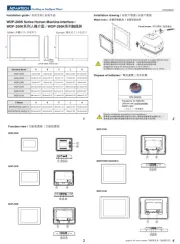
Advantech MIC-75M40 Manual


Læs gratis den danske manual til Advantech MIC-75M40 (12 sider) i kategorien Ikke kategoriseret. Denne vejledning er vurderet som hjælpsom af 2 personer og har en gennemsnitlig bedømmelse på 4.1 stjerner ud af 1.5 anmeldelser. Har du et spørgsmål om Advantech MIC-75M40, eller vil du spørge andre brugere om produktet?

Side 1/12
MIC-75M40 Startup Manual 1
Before you begin installing your card, please make sure
that the following items have been shipped:
1. MIC-75M40 Moduel p1-x1
P/N: MIC-75M40-00A1E
2. MIC-75M40 Startup Manual p1-x1 P/N: 20015M4000
3. Warranty Card P/N: 2190000902
4. SATA Cable x 1 P/N: 1700014518
5. SATA Power Cable x 1 P/N: 1700023566-02
6. Card Clamp Pad x 4 P/N:1990024989T000
7. Wall-Mount BKT (Left) p1-x1 P/N:
1960070545N001
8. Wall-Mount BKT (Righ) p1-x1 P/N:
1960070543N001
If any of these items are missing or damaged, please
contact your distributor or sales representative immediately.
Note: Acrobat Reader is required to view any PDF file.
Acrobat Reader can be downloaded at: get.
adobe.com/reader (Acrobat is a trademark of
Adobe)
MIC-75M40
PCIE Expansion Module for MIC-7 Series
Embedded System
Startup Manual
PCIe Slots
• One PCIex16 socket (PCIex8 signal)
Note 1: PCIEx8 power consumption supports to 35W.
• Three PCIex4 socket
Note 1: Each PCIEx4 supports 15W power consumption.
Note 2: MIC-75M40 does not supports MIC-7300 series
system.
Storage
• Internal SATA connector: 1
Note 1: MIC-75M40 supports 2x2.5’ HDD space and
one SATA signal is from main system.
Environment
• Operation Temperature:
-20 ~ 60° C with 0.7 m/sec air flow: with 1 x Industrial SSD
without PC expansion boards
0 ~ 45° C with 0.7 m/sec air flow: with 1 x 2.5” HDD
without PC expansion boards
• Storage Temperature: - 40 ~ 85° C (-40 ~185° F)
• Relative Humidity: 95% @ 40° C (non-condensing)
Mechanical
• Dimensions (H x W x D): 92 x 90 x 230 mm
Note 1: Please add FAN into i-module, when add-on
card total power consumption is over 45W.
Specications Packing List
For more information on this and other Advantech
products, please visit our website at:
http://www.advantech.com
http://www.advantech.com/eplatform
For technical support and service, please visit our
support website at:
http://support.advantech.com.tw/support/default.
aspx
This manual is for the MIC-75M40 Series Rev. A1.
Part No. 20015M4000
Printed in China
1st Edition
January 2016
2 MIC-75M40 Startup Manual
2. Undo 6x screws of MIC-75M40.
2
2
2
2
2
2
3. Remove i-door cover by MIC-7500 bottom cover and
assemble and secure cover in i-module’s bottom cover.
3
3
4. Assemble MIC-75M40 and MIC-7 series device and
secure 4x screws to integrate system.
3
3
3
3
Note: MIC-75M40 has 2 bolts and it must be aligned
into the holes at device.
The table below list the function of each of the connectors.
PCIE x 16 Socket
PCIEx4 Socket
12V Extral Power
SATA CON
SATA Power CON
5V Extral Power
FAN CON
PCIEx4 Socket
PCIEx4 Socket
(PCIE x 8 Signal)
Connectors
No. Item Function
1 SATAPWR1 SATA Power connector
2 SATA1 SATA connector
3 CPUFAN1 4 Pin FAN connector
4 PWR1 4 Pin Power connector (12V)
5 PWR2 4 Pin Power connector (5V)
6 PCIEx4 1/2/3 PCIEx4 Socket
7 PCIEx16_1 PCIE p2-x16 Socket
System Installation
MIC-7 series i-module can assemble with all MIC-7 series
IPC system.
1. Undo MIC-7 series system screws and remove the
bottom cover.
1
1
1
1
2
Simple Maintain Process
Jumpers and Connectors
Simple Maintain Process (Cont.)


Produkt Specifikationer

Mærke: Advantech
Kategori: Ikke kategoriseret
Model: MIC-75M40

Har du brug for hjælp?

Hvis du har brug for hjælp til Advantech MIC-75M40 stil et spørgsmål nedenfor, og andre brugere vil svare dig


Ikke kategoriseret Advantech Manualer

Ikke kategoriseret Manualer

Nyeste Ikke kategoriseret Manualer