Altronix PDS8 Manual
Altronix
Strømskinne
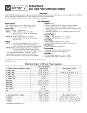
PDS8
| Mærke: | Altronix |
| Kategori: | Strømskinne |
| Model: | PDS8 |
Har du brug for hjælp?
Hvis du har brug for hjælp til Altronix PDS8 stil et spørgsmål nedenfor, og andre brugere vil svare dig
Strømskinne Altronix Manualer
29 August 2024
29 August 2024
29 August 2024
Strømskinne Manualer
Nyeste Strømskinne Manualer
10 Marts 2025
9 Marts 2025
27 Februar 2025
21 Februar 2025
20 Februar 2025
20 Februar 2025

31 December 2025

29 December 2024
7 December 2024
7 December 2024