AOI UH-OM1 Manual
AOI
fotokamera
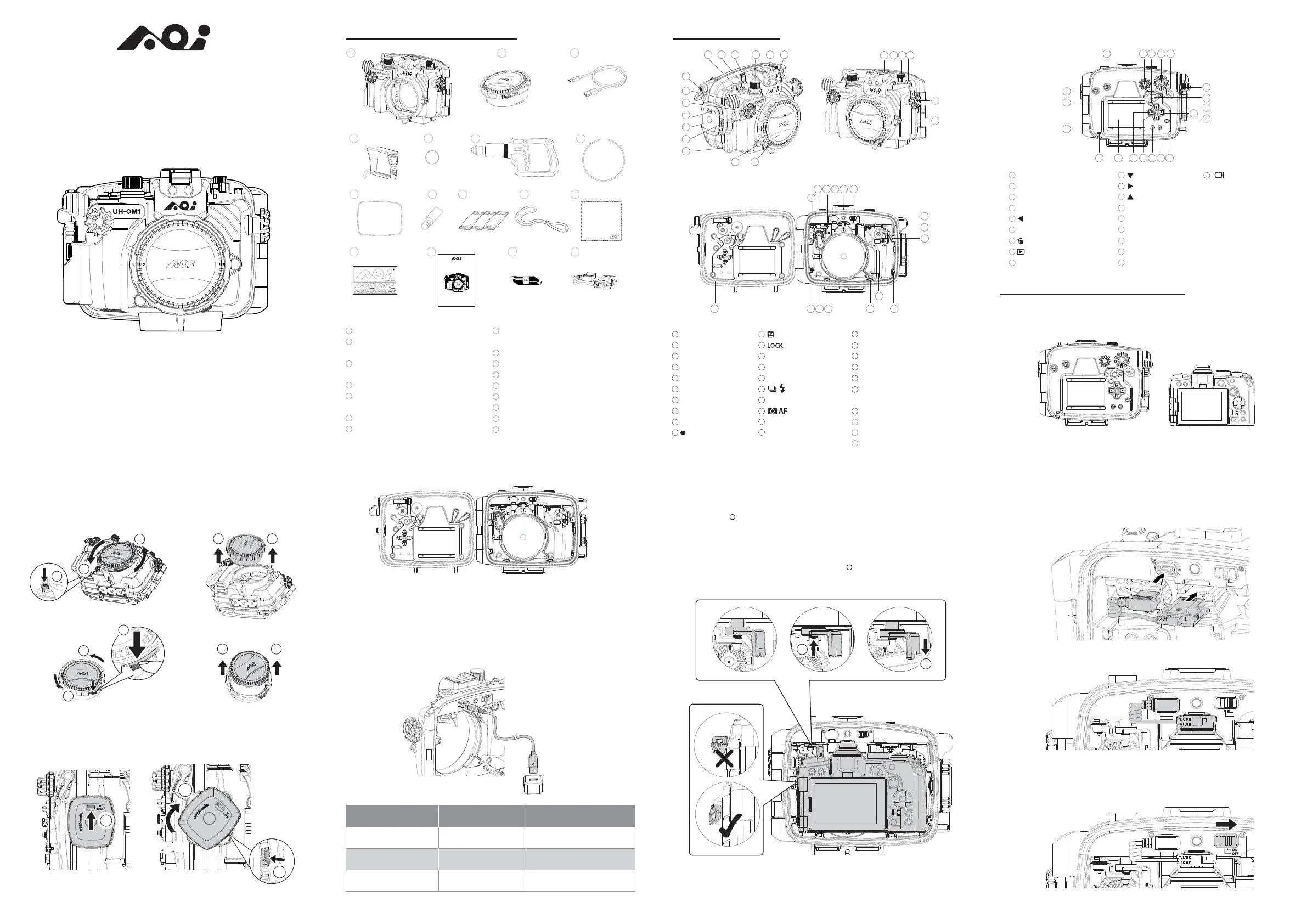
UH-OM1
| Mærke: | AOI |
| Kategori: | fotokamera |
| Model: | UH-OM1 |
Har du brug for hjælp?
Hvis du har brug for hjælp til AOI UH-OM1 stil et spørgsmål nedenfor, og andre brugere vil svare dig
fotokamera AOI Manualer
1 Oktober 2025
fotokamera Manualer
- Zeiss
- Kern
- Aquapix
- SereneLife
- Rollei
- Lumens
- AgfaPhoto
- Hamilton Buhl
- Hikvision
- Koblenz
- Digital Watchdog
- Vimar
- Aplic
- Sigma
- Bresser
Nyeste fotokamera Manualer

31 December 2026

31 December 2026

31 December 2026

31 December 2026

31 December 2026

30 December 2026

29 December 2026

29 December 2026

29 December 2026

28 December 2025