APC ProtectNet PRM4 Manual

APC Ikke kategoriseret ProtectNet PRM4

Læs nedenfor 📖 manual på dansk for APC ProtectNet PRM4 (2 sider) i kategorien Ikke kategoriseret. Denne guide var nyttig for 9 personer og blev bedømt med 4.5 stjerner i gennemsnit af 2 brugere

Side 1/2
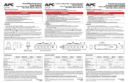
ProtectNet® Modular Data Line
Installation Manual
Surge Protection System
Thank you for purchasing APC’s Modular Data Line Surge Protection System. Please fill out the supplied Warranty Registration Card or an on-line Product Warranty Registration form at www.apc.com.
APC’s Modular Data Line Surge Pr variety of interchangeable surgotection System consists of a e suppression modules installed in either a four position “PRM4” or a 24 position “PRM24” chassis with the mounting hardware and ground wire. A list
of the modules that are available, and the types of data lines they protect are provided below. The PRM4 is designed to mount inside a home wiring enclosure. The PRM24 is designed to mount in a standard 19-inch rack enclosure.
This manual provides basic installation information for the PRM4 chassis and associated modules. For PRM24 installation information, reference APC manual 990-1383A.
Note: Procedures provided in this document are not intended to supersede local standards or codes. Reference the Telecommunications Industries Association and Electronic Industries Alliance publication “Commercial Building,
Telecommunications Cabling Standard, General Requirements” (document number TIA/EIA-568-B.1-2001) to ensure the system wiring is installed properly.
Safety
Please read and save these instructions, and observe the following safety precautions.
Use the system in a protected environment only.
Never install telephone wiring or coaxial cable during a lightning storm.
Follow the installation instructions carefully. The current limiting feature of this product could be rendered inoperable if the product is improperly installed.
w
w
w
.apc.com
®
Completed Assembly
Remove Install
Completed Assembly
Figure 2. Side-by-Side Mounting
Figure 1. Stacked Mounting and Module Installation
Detail A - PRMLB (Optional) Mounting Bracket Orientation
General Installation
Other Considerations
Do not install this device in an environment where the operating temperature exceeds 0 to 40 oC (32 to 104oF).
Do not install this device where the relative humidity exceeds 95%, non-condensing.
Do not store this device in an environment that exceeds 0 to 45oC (32 to 113oF).
Chassis Installation
APC recommends the ProtectNET PRM4 Data Line Surge Protection chassis (X
X
X
XX in Figure 1) be installed using the optional mounting brackets (see Detail A, Figure 1) that
are available from APC (order PRMLB). In applications where more than one PRM4 chassis is used, the chassis’ can be stacked (see Figure 1), or mounted side-by-side (see
Figure 2) using the joining plate Y
Y
Y
YY, and the machine screws supplied with the chassis.
Module Installation
The PRM4 chassis is designed to accomodate up to four data line or coaxial cable modules. To install a module, remove the two machine screws Z
Z
Z
ZZ that secure the insert
plate [
[
[
[[ \
\
\
\\ to the "U bracket" bezel holder . Remove one of the blank panels ]
]
]
]] by pulling it straight out of the chassis. Align the module, either ^
^
^
^^ or _
_
_
__, with the groove
in the chassis and slide the module fully into the chassis. After installing all the required modules, replace the "U bracket" bezel holder \
\
\
\\, and install the insert plate. The U
bracket bezel holder is provided to prevent modules from being accidently removed from the chassis.
Telephone or Coaxial Cable Installation
To install a data line cable `
`
`
``, connect the input RJ-45 connector to the signal source, and then connect to the upper data connector on the module. Connect a data line cable
from the module’s lower connector to the equipment to be protected. To accomodate four mNote: odules, the four blank panels in the center of the module must be removed.
To install coaxial cables a
a
a
aa, connect one end of the cable to the signal source. Connect the other end of the cable to the upper input connector of the module marked IN.
Connect the output cable "F" connector from the module’s lower connector marked OUT to the device to be protected (CATV, DSS, cable modem, or antenna system).
Grounding
The chassis must be grounded to a proper protective earth ground (see Figure 3). In a typical home/office environment, this can be accomplished by grounding the chassis to
the transient voltage surge supression (TVSS) ground of an uninterruptable power supply (UPS), or to your computer chassis. If the chassis is mounted in a structured wiring
cabinet, ground the chassi chine screw, and threads to earth ground via the cabinet's earth ground connection. A ground wire, ma ed mounting hole are provided to be used
when grounding the chassis.
X
X
X
XX
Y
Y
Y
YY
Z
Z
Z
ZZ
[
[
[
[[
\
\
\
\\
]
]
]
]]
^
^
^
^^
_
_
_
__
`
`
`
``
a
a
a
aa
OR
Y
Y
Y
YY


Produkt Specifikationer

Mærke: APC
Kategori: Ikke kategoriseret
Model: ProtectNet PRM4

Har du brug for hjælp?

Hvis du har brug for hjælp til APC ProtectNet PRM4 stil et spørgsmål nedenfor, og andre brugere vil svare dig


Ikke kategoriseret APC Manualer
APC

APC ACAC75017 Manual

30 Maj 2024
APC

APC ACAC10051 Manual

30 Maj 2024
APC

APC ACRD601P Manual

30 Maj 2024
APC

APC AP9566 Manual

30 Maj 2024
APC

APC AR7303G Manual

14 Maj 2024
APC

APC ER7VCM42 Manual

21 April 2024
APC

APC AR7706 Manual

12 April 2024

Ikke kategoriseret Manualer

Nyeste Ikke kategoriseret Manualer