Ashly RPS-18 Manual


Læs gratis den danske manual til Ashly RPS-18 (6 sider) i kategorien Ikke kategoriseret. Denne vejledning er vurderet som hjælpsom af 28 personer og har en gennemsnitlig bedømmelse på 5.0 stjerner ud af 14.5 anmeldelser. Har du et spørgsmål om Ashly RPS-18, eller vil du spørge andre brugere om produktet?

Side 1/6
Ashly WR-5 Remote Control
1. Introduction
The WR-5 is a microprocessor based serial data remote control
unit for Ashly NE or NX products. Compatible products currently
include Pema ampliers, ne8800 and ne4800 system processors,
the ne24.24M matrix processor, all models of the NE multichannel
power ampliers, and nXe/nXp ampliers. Using Proteane software,
six function select buttons and two parameter adjust buttons are
available to control a limited range of assigned functions within
their host product. Up to four WR-5 units can be daisy-chained and
phantom powered from one host, and even more can be added using
an in-line power supply adapter such as the Ashly RPS-18. Note:
When an WR-5 is connected to an Ashly product, no other serial
communications devices, including the Ashly RD-8C remote fader
controller, may be used with that product.
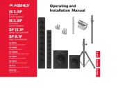
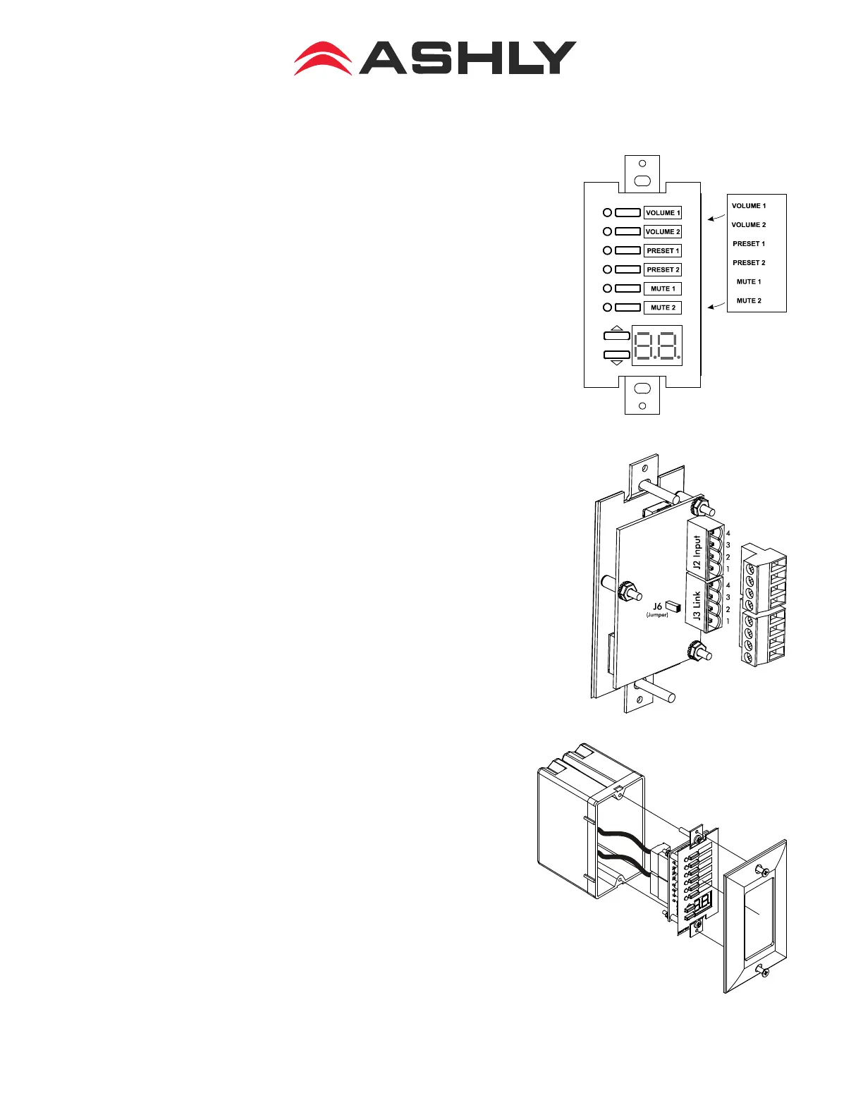
The WR-5 is designed to t into a standard US electrical wall
box. Electrical connections to the host unit are made using a four
conductor low gauge wire terminated with Euroblock connectors.
There is also a two pin jumper labeled “J6” which requires the
provided female jumper to be installed in specic situations (see
section 2). Note: The WR-5E is the electrical equivalent to the WR-
5, but designed to t into a UK electrical box. A standard decora
plate (not included) can be purchased separately to cover the WR-5
electrical box and satisfy the aesthetic needs of the installation.
Note: Avoid static shock disruptions by mounting the WR-5 to an
earth-grounded metal wall box, or by earth-grounding the metal
cover plate. This prevents potential static discharge from owing
back through the data wires to the host device.
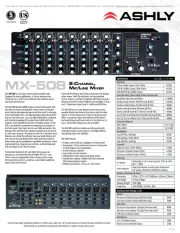
Each of six buttons on the WR-5 can be programmed through
Proteane Software to engage one of the following functions (if
available): preset recall, preset scroll, gain control, channel
engage/mute, zone source selection, logic output active high,
logic output active low, and matrix mixer, with a green LED
next to each button to display active status.
To the right of the ve programmable buttons is a pocket in
the mylar overlay for a paper function label to be inserted. See
section 6 for a blank template which can be copied, or get an
editable label template from the Ashly website. The two other
buttons are used to adjust function parameters, indicated by the
LED character display.
WR-5 Front View with Label
WR-5 Rear View
WR-5 Wall-Box Assembly
Ashly Audio Inc.
847 Holt Road Webster, NY 14580-9103 Phone: (585) 872-0010
Toll-Free: (800) 828-6308 Fax: (585) 872-0739 ashly.com
Operating Manual - WR-5 Remote Control
2
2. Wiring a WR-5
The WR-5 uses a four conductor
phantom powered serial bus to
connect to its host unit or to an
additional WR-5. Up to four WR-5
remotes can be powered from one
host unit. Ashly offers the RPS-18,
an inline power booster for use in
applications that require more than
four WR-5 units. Four conductor
telephone wire is suitable for all
wiring, as well as CAT5, but if
shielded wiring is used be sure to
ground the source end of the shield.
Under no circumstances should
shielding be left unconnected to
ground, as the added line capacitance
will degrade the data signal.
Wiring in series: If more than
one WR-5 is being wired in series,
connect the next length of four
conductor bus wire from the rst
WR-5’s “LINK” connector to the
following WR-5 “INPUT” connector, and so on,
until the last WR-5 is wired. On the last WR-5 in
series wiring, and even if there is only one WR-
5, install the female jumper J6 on the back of the
pcb to terminate the serial data bus, and make sure
all prior WR-5 units have the J6 jumper removed.
Maximum cable length is 1,000 ft between the host
unit and the rst WR-5, and 1,000 ft between each
subsequent WR-5.
Wiring in parallel from a central location:
Some installations are more suited to wiring
multiple WR-5 units from one central location
rather than daisy-chaining one WR-5 to the next.
Using a punch down or screw terminal block wired
to the host unit’s data connector, each WR-5 uses
one four conductor cable terminated with a single
euroblock connector originating from the punch
down block. The +18 and ground connections get
parallel wired to each WR-5 (up to four), but the
data signal still gets wired In the following in series
manner: Wire the host unit’s Data Out (pin 2) to
the punch down block, then out from there to the


Produkt Specifikationer

Mærke: Ashly
Kategori: Ikke kategoriseret
Model: RPS-18

Har du brug for hjælp?

Hvis du har brug for hjælp til Ashly RPS-18 stil et spørgsmål nedenfor, og andre brugere vil svare dig


Ikke kategoriseret Ashly Manualer

Ashly

Ashly Protea DSP360 Manual

5 September 2024
Ashly

Ashly AW 8.2T+ Manual

4 September 2024
Ashly

Ashly CA-1.52 Manual

2 September 2024
Ashly

Ashly CA-1.54 Manual

2 September 2024
Ashly

Ashly RPS-18 Manual

26 August 2024
Ashly

Ashly Protea 4.8SP Manual

26 August 2024

Ikke kategoriseret Manualer

Nyeste Ikke kategoriseret Manualer