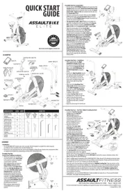
Seat / Slide Assembly (A)
Seat Slide Cover - Front (349)
Speed Sensor Cable - Lower (384)
Speed Sensor Cable - Upper (313a)
Speed Sensor Cable - Upper (313b)
Console Mast Covers (316)
Handlebar - Right (322-A)
Handlebar Pivot Covers (324)
HARDWARE DESCRIPTION DRAWING QUANTITY
Ø19.0OD x Ø8.5ID x 1.2t (305)
Ø22OD x 10.5ID x 2.0t (328)
Seat / Slide Assembly (A)
Seat Slide Cover Assembly
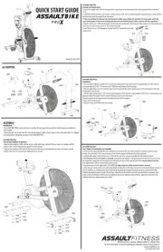
Front & Rear Stabilizer Installation
• With the assistance of a second person,
raise front portion of the Main Frame
so the unit rests on the rear stabilizer
receiver and the seat slider.
• While supporting the unit, align the
Rear Stabilizer (303-A) with the
stabilizer receiver of the .Main Frame
• Place one onto #305 M8 Flat Washer
each of the #304 M8 x 20mm Socket
Head Hex Screws. Loosely thread
the M8 Socket Head Hex Screw/M8
Flat Washer Assembliess through the
underside of the Rear Stabilizer (303)
and into the . Repeat these Main Frame
steps for the Front Stabilizer (302-A)
and tighten the screws rmly with the
• With assistance, safely return the
ASSAULTBIKE ELITE to an upright
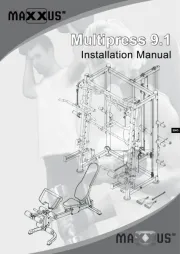
Assembly Step Three – Handlebars
• While supporting the the Right
Handlebar Assembly (322-A), align
the lower pivot of the handlebar and
slide it onto the Linkage Arm Pivot
Pin #328 Flat Washer. Install a and
#329 M10 Nylock Nut and tighten
• Rotating the around Right Handlebar
the lower pivot, align the upper pivot
pin with the receiver on the main
frame. Thread the pivot pin into the
frame with a clockwise rotation and
tighten rmly with the provided
• Align one of the Handlebar Pivot
Covers (324) with the mounting holes
on the , and loosely Right Handlebar
thread the two #325 Cap Head Hex
Screws through the cover and into the
handlebar. Tighten rmly.
• Install a Foot Peg (326) onto the
handlebar pivot, rotating it clockwise.
• Slide the long, 6mm hex wrench
through the holes milled into the peg
and tighten rmly with a clockwise
• Repeat the above steps for the left side.
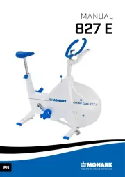
• The ASSAULTBIKE ELITE requires only minor assembly. All tools required to complete the initial setup and
assembly have been included in the Assembly Hardware Kit.
• Remove the unit and all parts from the carton and packaging. Conrm all parts shown in the section above titled
As Shipped are included before attempting assembly of the ASSAULTBIKE ELITE.
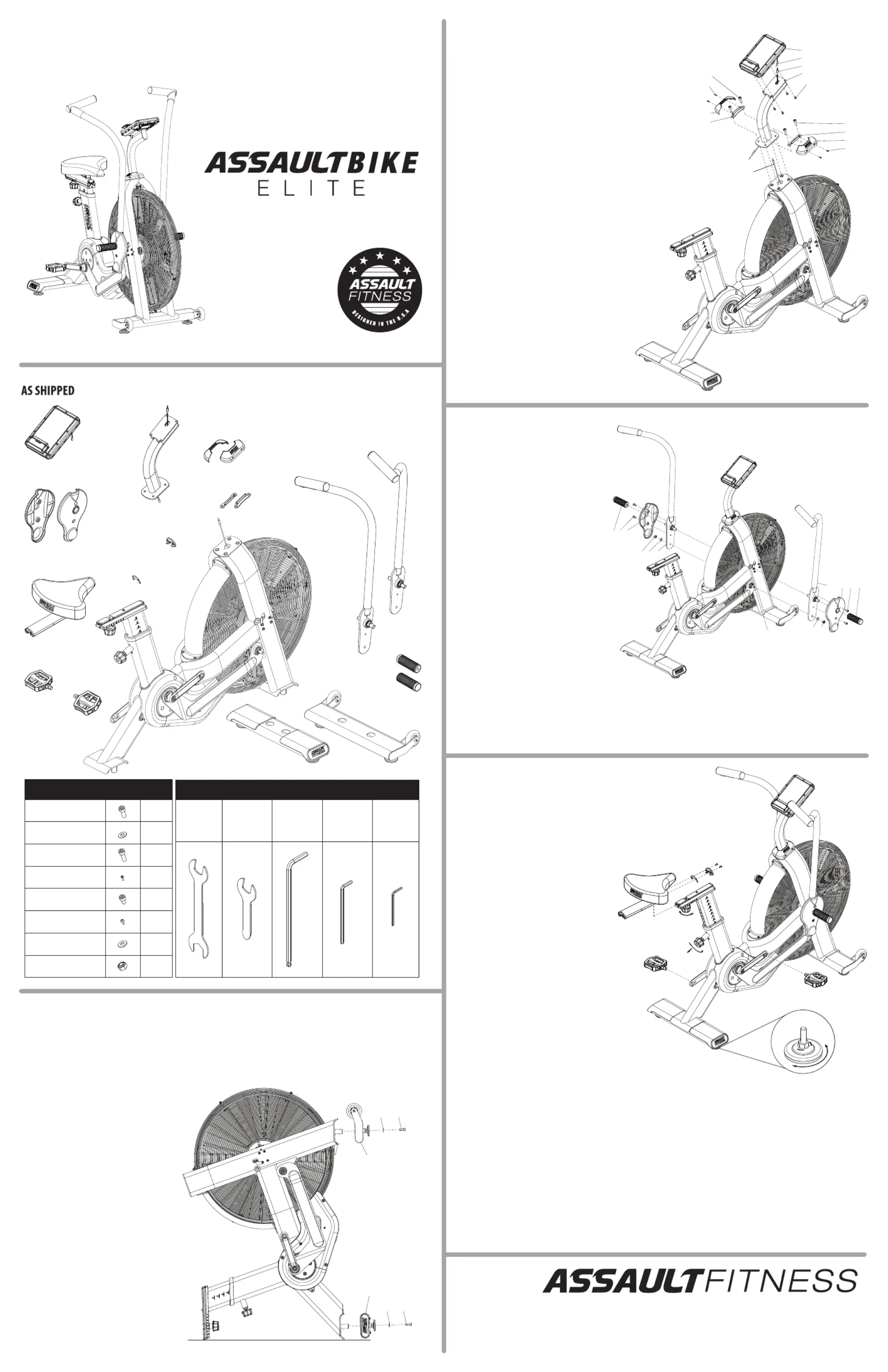
Assembly Step Four – Seat Post, Pedals & Leveling the Unit
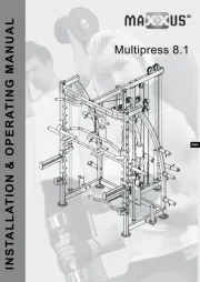
Assembly Step Two: Console Mast
• Remove the four from the backside of the #318 Phillips Screws
Console (314) Connect the Speed Sensor Cable and set aside.
(314a) Speed extending from the backside of the console with
Sensor Cable – Upper (313a) and carefully tuck the cable into
• Align the mounting holes located in the back of the Console
(314) Console Mast (312) with the holes in the and loosely
thread the four through the console mast #318 Phillips Screws
and into the console. Tighten rmly.
• The Speed Sensor Cable - Upper (313) is pre-installed and
should be extending from the top and bottom of the Console
Mast Speed Sensor Cable – . Connect the lower end of the
Upper (313b) Speed Sensor Cable – Lower (384) with the .
• Align the Seat Slide Cover Assembly –
Front (349-A) with the forward edge of the
Seat / Slide Assembly (A) and mount it with
the two . #345 - 4mm Button Head Hex Screws
• Install the onto the Right Pedal (015-1) Right
Crank a few threads by hand with a clockwise
rotation of the axle. Insert the 6mm Hex Wrench
into the end of the Right Pedal (015-1) axle
inside of the crank arm and tighten rmly.
• The Left Pedal (016-1) axle threads are reversed,
meaning the axle rotates in the opposite
direction from most screws or bolts for installation. Engage the
rst few threads of the Left Pedal Left Crank axle into the by hand with a counter-clockwise rotation, then
tighten rmly with the 6mm Hex Wrench.
• Select a suitable space for operation of the ASSAULTBIKE ELITE. Move the unit to the desired location by raising
the rear stabilizer o the ground until the transport wheels touch the ground. Slowly push the unit into place.
Ensure there is 0.5 m (19.7 in.) of clearance on all sides of the bike.
• Ensure the unit is level and does not rock by adjusting the Stabilizer Leveling Feet. There are two feet on the
Front Stabilizer and two on the Rear Stabilizer. As a starting point, loosen each foot by threading the assembly
downward/clockwise, and then thread the locknuts downward (clockwise) against the foot base. Check the
unit for stability and make any adjustments as necessary. Once stable, lock the Stabilizer Leveling Feet in
place by tightening the jam nut upward/counter-clockwise, against the underside of the stabilizer to lock the
current position of each foot.
• Congratulations, your new ASSAULTBIKE ELITE is fully assembled and ready for use. Please read all included
information, user guides and warnings before use.
• Align the mounting plate for the Console Mast
(312) Main Frame with the mounting holes in the .
Carefully tuck the console connectors and cables
into the frame. Loosely thread two M8 x 25mm Cap
Head Hex Screws (317) Console Mast through the
Cover Mounting Plate (315) Console Mast and
(312) Main Frame and into the . Repeat the above
steps and install the #315 Console Mast Cover
Mounting Plate on the opposite side. Tighten all
four screws rmly with the 6mm Hex Wrench.
• Align one of the Console Mast Covers
(316) with the mounting holes in the
Console Mast Cover Mounting Plate
(315) #319 M4 and loosely thread two
Socket Head Hex Screws through the
one cover and into the plate. Repeat this
process for the opposite side, and tighten
• To raise the Seat Post Assembly
(336-A) Seat Post loosen the
Pop-Pin (369) and pull it
outward while sliding the seat
post upward. Release the pop-pin
and ensure the seat post has
positive engagement in one of
the eleven height positions.
• Align the channel in the
underside of the Seat / Slide
Assembly (A) with the rail on
the Seat Post Assembly (336-A)
and slide it all the way forward.
It may be necessary to loosen the
Seat Slide Adjuster Knob (338).
Part #23-AS-418 US-English v1.0 09-Oct-20
5803 Newton Drive, Carlsbad, California, USA 92008 Phone: 1.888.815.5559
For more information or questions regarding your equipment, please visit our website at www.assaulttness.com