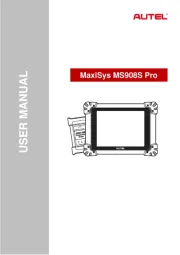
Autel MaxiCOM MK808TS Manual

Autel Ikke kategoriseret MaxiCOM MK808TS

Læs nedenfor 📖 manual på dansk for Autel MaxiCOM MK808TS (162 sider) i kategorien Ikke kategoriseret. Denne guide var nyttig for 9 personer og blev bedømt med 4.5 stjerner i gennemsnit af 2 brugere

Side 1/162
i
Trademarks
Autel®, MaxiSys®, MaxiDAS®, MaxiScan®, MaxiTPMS®, MaxiRecorder®, and
MaxiCheck® are trademarks of Autel Intelligent Technology Corp., Ltd., registered in
China, the United States and other countries. All other marks are trademarks or
registered trademarks of their respective holders.
Copyright Information
No part of this manual may be reproduced, stored in a retrieval system or transmitted, in
any form or by any means, electronic, mechanical, photocopying, recording, or otherwise
without the prior written permission of Autel.
Disclaimer of Warranties and Limitation of Liabilities
All information, specications and illustrations in this manual are based on the latest
information available at the time of printing.
Autel reserves the right to make changes at any time without notice. While information of
this manual has been carefully checked for accuracy, no guarantee is given for the
completeness and correctness of the contents, including but not limited to the product
specications, functions, and illustrations.
Autel will not be liable for any direct, special, incidental, indirect damages or any
economic consequential damages (including the loss of prots).
IMPORTANT
Before operating or maintaining this unit, please read this manual carefully, paying extra
attention to the safety warnings and precautions.
For Services and Support
pro.autel.com
www.autel.com
1- -288-3587/1-855-AUTELUS (North America) 855
0086-755-86147779 (China)
Support@autel.com
For technical assistance in all other markets, please contact your local selling agent.
ii
Safety Information
For your own safety and the safety of others, and to prevent damage to the device and
vehicles upon which it is used, it is important that the safety instructions presented
throughout this manual be read and understood by all persons operating or coming into
contact with the device.
There are various procedures, techniques, tools, and parts for servicing vehicles, as well
as in the skill of the person doing the work. Because of the vast number of test
applications and variations in the products that can be tested with this equipment, we
cannot possibly anticipate or provide advice or safety messages to cover every
circumstance. It is the automotive technician s responsibility to be knowledgeable of the
system being tested. It is crucial to use proper service methods and test procedures. It
is essential to perform tests in an appropriate and acceptable manner that does not
endanger your safety, the safety of others in the work area, the device being used, or the
vehicle being tested.
Before using the device, always refer to and follow the safety messages and applicable
test procedures provided by the manufacturer of the vehicle or equipment being tested.
Use the device only as described in this manual. Read, understand, and follow all safety
messages and instructions in this manual.
Safety Messages
Safety messages are provided to help prevent personal injury and equipment damage.
All safety messages are introduced by a signal word indicating the hazard level.
DANGER
Indicates an imminently hazardous situation which, if not avoided, will result in death or
serious injury to the operator or to bystanders.
WARNING
Indicates a potentially hazardous situation which, if not avoided, could result in death or
serious injury to the operator or to bystanders.
Safety Instructions
The safety messages herein cover situations Autel is aware of. Autel cannot know,
evaluate or advise you as to all of the possible hazards. You must be certain that any
condition or service procedure encountered does not jeopardize your personal safety.
iv
CONTENTS
1 USING THIS MANUAL ................................................................................................... 1
C ONVENTIONS................................................................................................................... 1
2 GENERAL INTRODUCTION .......................................................................................... 2
M M MK808TS T 2AXICO ABLET ...........................................................................................
VCI V C I EHICLE OMMUNICATION NTERFACE ...................................................................... 5
O A THER CCESSORIES ........................................................................................................ 7
3 GETTING STARTED ...................................................................................................... 9
P U 9OWERING P ..................................................................................................................
P D OWERING OWN............................................................................................................ 13
4 DIAGNOSTICS ............................................................................................................. 14
E V C STABLISHING EHICLE OMMUNICATION .......................................................................... 14
G S ETTING TARTED ..........................................................................................................16
V I EHICLE DENTIFICATION .................................................................................................. 17
N AVIGATION .................................................................................................................... 21
D IAGNOSIS...................................................................................................................... 24
H F OT UNCTIONS.............................................................................................................. 36
G OBDII O ENERIC PERATIONS .......................................................................................... 37
E D XITING IAGNOSTICS......................................................................................................41
5 SERVICE ...................................................................................................................... 42
O R S IL ESET ERVICE ........................................................................................................42
E P B (EPB) S LECTRIC ARKING RAKE ERVICE ....................................................................... 44
B M S (BMS) S ATTERY ANAGEMENT YSTEM ERVICE .............................................................. 47
S A S (SAS) S TEERING NGLE ENSOR ERVICE .......................................................................52
D P F (DPF) S IESEL ARTICLE ILTER ERVICE.......................................................................... 54
I (IMMO) S MMOBILIZER ERVICE ......................................................................................... 61
6 TPMS ............................................................................................................................ 63
G S ETTING TARTED ..........................................................................................................63
V S EHICLE ELECTION ........................................................................................................ 65
TPMS C HECK................................................................................................................. 68
TPMS D IAGNOSIS ........................................................................................................... 69
S P ENSOR ROGRAMMING ..................................................................................................75
TPMS R ELEARN ............................................................................................................. 79
TPMS OEM P N . BY ART O ............................................................................................... 83
7 BATTERY TEST ........................................................................................................... 88
M BT506 T AXIBAS ESTER................................................................................................ 88
v
T P EST REPARATION ......................................................................................................... 90
I - T N VEHICLE EST ............................................................................................................. 92
O - T UT VEHICLE EST .......................................................................................................... 99
8 DATA MANAGER ....................................................................................................... 101
O PERATIONS ................................................................................................................. 101
9 SETTINGS .................................................................................................................. 107
U NIT............................................................................................................................. 107
L ANGUAGE .................................................................................................................... 107
P S RINTING ETTINGS ....................................................................................................... 108
R SEPORT ETTINGS ........................................................................................................ 109
M ULTITASK ...................................................................................................................109
TPMS M ARKET ............................................................................................................. 109
TPS P . S ROG ETTING ..................................................................................................... 110
A U UTO PDATE ............................................................................................................... 110
C O AR RDER .................................................................................................................. 110
S SYSTEM ETTINGS......................................................................................................... 110
A BOUT.......................................................................................................................... 111
10 UPDATE ..................................................................................................................... 112
T U ABLET PDATE ............................................................................................................ 112
M VCI M U AXI INI PDATE .................................................................................................. 114
11 VCI MANAGER ........................................................................................................... 115
12 SHOP MANAGER ......................................................................................................117
V H EHICLE ISTORY.......................................................................................................... 118
WORKSHOP NFORMATIONI .............................................................................................. 120
C M USTOMER ANAGER.................................................................................................... 120
13 ACADEMY .................................................................................................................. 122
14 REMOTE DESK .......................................................................................................... 123
15 MAXIFIX ..................................................................................................................... 125
N AVIGATION .................................................................................................................. 125
O PERATIONS ................................................................................................................. 127
16 SUPPORT .................................................................................................................. 133
P R RODUCT EGISTRATION ............................................................................................... 133
S S L UPPORT CREEN AYOUT.............................................................................................134
M A Y CCOUNT ................................................................................................................ 134
C OMMUNITIES ............................................................................................................... 135
D L ATA OGGING..............................................................................................................136
vi
T RAINING ...................................................................................................................... 137
FAQ ............................................................................................................................ 137
17 QUICK LINK ...............................................................................................................138
18 FUNCTION VIEWER .................................................................................................. 139
19 DIGITAL INSPECTION ............................................................................................... 141
A A DDITIONAL CCESSORIES ............................................................................................. 141
I H A MAGER EAD CCESSORIES .......................................................................................... 142
A A . CCESSORY SSEMBLY ................................................................................................ 143
T S ECHNICAL PECIFICATIONS ........................................................................................... 144
O PERATIONS ................................................................................................................. 145
20 MAINTENANCE AND SERVICE ................................................................................147
M I AINTENANCE NSTRUCTIONS ......................................................................................... 147
T C ROUBLESHOOTING HECKLIST ...................................................................................... 148
A B U BOUT ATTERY SAGE ................................................................................................149
S P ERVICE ROCEDURES .................................................................................................. 150
21 COMPLIANCE INFORMATI ON .................................................................................. 153
FCC C OMPLIANCE......................................................................................................... 153
SAR ............................................................................................................................ 154
RF ARNING TATEMENTW S .............................................................................................. 154
R C OHS OMPLIANCE ...................................................................................................... 154
CE OMPLIANCEC ........................................................................................................... 154
22 WARRANTY ............................................................................................................... 156
3
4. TPMS Service Symbol indicates the position of the embedded TPMS antenna.
The power LED displays green, yellow or green depending on power level and operating
state.
A. Green
Illuminates green when the tablet is charging and the battery level is above 90%.
Illuminates green when the tablet is powered on and the battery level is above
15%.
B. Yellow
Illuminates yellow when the tablet is charging and the battery level is below 90%.
C. Red
Illuminates red when the tablet is powered on and the battery level is below 15%.
5. Collapsible Stand extends from the back to allow hands-free viewing of the tablet.
6. Heat Sink
7. MaxiVCI Mini Holder
8. Built-in Battery
Figure 2-3 MaxiCOM MK808TS, Top View
9. Mini USB OTG Port
10. Micro SD Card Slot holds the micro SD card.
11. HDMI (High-Denition Multimedia Interface) Port
12. USB Port
Figure 2-2 MaxiCOM MK808TS, Back View
4
13. Lock/Power Button turns the device on & o with long press, or locks the screen
with short press.
Power Sources
The tablet can receive power from any of the following sources:
Internal Battery Pack
External Power Supply
Internal Battery Pack
The tablet can be powered with the internal rechargeable battery, which if fully charged
can provide sucient power for about 7 hours of continuous operation.
External Power Supply
The tablet can be powered from a wall socket using the USB charging cable and the USB
external power adapter. The external power supply also charges the internal battery pack.
Technical Specications
Table 2-1 Specications
Item
Description
Recommended Use
Indoor
Operating System
AndroidTM 4.4.2, KitKat
Processor
Cortex-A9 processor (1.5 GHz)
Memory
64 GB
Display
7-inch LCD capacitive touchscreen with 1024 x
600 resolution
Connectivity
Mini USB 2.0
USB 2.0
Wi- Fi
HDMI Type A
Micro SD card (supports up to 32 GB)
Sensors
Light sensor for brightness auto changing
Audio Output
Buzzer
Power and Battery
3.7 V/5000 mAh lithium-polymer battery
Charges via 5 V DC power supply
6
4. USB Port provides the easiest connection between the device and the tablet via
a USB cable.
Table 2-2 Power LED
LED
Color
Power
Green
Red
Table 2-3 Connection LED
LED
Color
Description
Connection
Green
Lights solid green when the device is
successfully connected via the USB cable but is
not communicating with the vehicle.
Blinks green when the device is successfully
connected via the USB cable and is
communicating with the vehicle.
Blue
Lights solid blue when the device is successfully
connected via Bluetooth but is not
communicating with the vehicle.
Blinks blue when the device is successfully
connected via Bluetooth and is communicating
with the vehicle.
7
Technical Specications
Table 2-4 Specications
Item
Description
Communications
Bluetooth V.2.1 + EDR
USB 2.0
Wireless Frequency
2.4 GHz
Input Voltage Range
12 V DC to 24 V DC
Supply Current
150 mA @ 12 VDC
Operating Temperature
0 to 50 °C (32 to 122 °F) (ambient)
Storage Temperature
- to 70 °20 C (-4 to 158 (ambient) °F )
Dimensions
(L x W x H)
47 mm ( ) x mm ( ) x mm ( ) 1.7” 23 0.9” 51 2.0”
Weight
33.1g (0.07 lb.)
Power Sources
The MaxiVCI Mini operates on 12-volt vehicle power, which received through the is
vehicle DLC. The unit powers on whenever it is connected to the vehicle ’s ’s DLC.
Other Accessories
MaxiVCI Mini
Connects to the vehicle’s DLC and provides wireless connection
between the tablet and the vehicle.
USB Cable (for test)
2 m
USB Cable (for charging)
90 cm
9
3 Getting Started
Ensure the tablet sucient charged or is connected to the external power supply (see is
Power Sources).
NOTE
The images and illustrations depicted in this manual may dier slightly from the actual
ones.
Powering Up
Long press the Lock/Power button on the top right side of the tablet to power on the unit.
The power LED light will illuminate green. The system boots up and displays the lock
screen. Slide the Lock icon to the left to enter the MaxiCOM Job Menu or slide to the
right to unlock.
Figure 3-1 Sample MaxiCOM MK808TS Job Menu
1. Application Buttons
2. Locator and Navigation Buttons
3. Status Icons
NOTE
The tablet screen is locked by default when rst powered on. It is recommended to lock
the screen to protect the information in the system and reduce the power consumption.
The touch screen navigation is menu driven enabling quickly access to functions and
features by tapping on options headings and answering dialog windows. Detailed
descriptions of the menu structures are found in the application chapters.
11
Button
Name
Description
MaxiFix
Launches the MaxiFix platform which provides the most
compatible and abundant repair techniques and
diagnostics database. See for details. MaxiFix
Support
Launches the Support platform which synchronizes
Autel s on-line service base station with the MaxiCOM
tablet. See for details. Support
Quick Link
Provides associated website bookmarks to allow quick
access to product update, service, support and other
information. See for details. Quick Link
Function
Viewer
Provides quick search for the supported functions and
vehicles of Autel diagnostic tools. See Function Viewer
for details.
Digital
Inspection
Congures the unit to operate as a video scope device
by connecting to an Imager head cable for close vehicle
inspections. See for details. Digital Inspection
Locator and Navigation Buttons
Operations of the Navigation buttons at the bottom of the screen are described in the
table below:
Table 3-2 Locator and Navigation Buttons
Button
Name
Description
Locator
Indicates which screen you are on. Swipe the
screen left or right to view the previous or next
screen.
Back
Returns to the previous screen.
Android Home
Returns to Android System s Home screen.
Recent Apps
Displays a list of applications that are currently in
use. T an app icon to launch. To remove an ap
app, swipe it to the top or bottom.
Chrome
Launches the Android built-in browser.
12
Button
Name
Description
Screenshot
Takes a screenshot when you want to save the
displayed information.
MaxiCOM Home
Returns to MaxiCOM Job Menu from other
operations.
VCI
Opens the VCI Manager application. The check
at the bottom right corner indicates the tablet is
communicating with the MaxiVCI Mini. An will X
display if the tablet is not connected to VCI.
TPMS Shortcut
Returns to the TPMS screen .
Diagnostics
Shortcut
Returns to the Diagnostics screen.
Service Shortcut
Returns to the Service screen.
System Status Icons
As the tablet is working with the Android operating system you may refer to Android ,
documents for more information.
By up sliding the bottom right corner, a Shortcuts Panel will be displayed, on which you
are allowed to set various system settings of the tablet. Operations of each button on the
panel are described in the table below:
NOTE
The shortcuts buttons will be highlighted when enabled, and dimmed when disabled.
Table 3-3 System Status Icons
Button
Name
Description
Calculator
Launches calculator when pressed.
Clock
Launches clock when pressed.
Bluetooth
Enables/disables Bluetooth when pressed.
Wi- Fi
Enables/disables Wi- when pressed. Fi
Airplane Mode
Enables/disables Airplane Mode when pressed.
System Settings
Launches the Android System Settings screen
when pressed.
13
Powering Down
All vehicle communications must be terminated before shutting down the tablet. A
warning message displays if you attempt to shut down the tablet while it is communicating
with the vehicle. Forcing a shut-down while communicating may lead to ECM problems
on some vehicles. Please exit the Diagnostics application before powering down.
To power down the tablet
1. Long press the Button. Lock/Power
2. Tap tion. Power o op
3. Tap , the tablet will turn o in a few seconds. OK
Reboot System
In case of system crash, long press the button and tap option to a Lock/Power Reboot
reboot the system.
20
Manual VIN Input
For vehicles not supporting the Auto VIN Scan function, you may manually enter the
vehicle VIN.
To perform Manual VIN Input
1. Tap the application button from the MaxiCOM Job Menu. The Diagnostics
Vehicle Menu displays.
2. Tap the button on the top toolbar to open the dropdown list. VIN Scan
3. Select . Manual Input
4. Tap the input box and enter the correct VIN.
5. Tap Once the vehicle is identied, the Vehicle Diagnostics screen Done.
displays.
6. Tap to exit Manual Input. Cancel
Automatic Selection
The Automatic Selection can be selected after selecting the test vehicle manufacturer.
Figure 4-6 Sample Diagnostic Screen
Figure 4-7 Sample Selection Screen
30
To erase codes
1. Tap Trouble Codes Erase Codes on the Function Menu, then tap .
2. A warning message displays to inform you of data loss when this function is
applied.
a) Tap Yes to continue. A confirming screen displays when the operation is
successfully done.
b) Tap to exit. No
3. Tap on the confirming screen to exit Erase Codes. ESC
4. Perform the function again to check if the code erasing is Read Codes
successful.
Live Data
When this function is selected, the screen displays the data list for the selected module.
The items available for any control module vary from one vehicle to another. The
parameters display in the order that they are transmitted by the ECM, so expect variation
between vehicles. Gesture scrolling allows you to quickly move through the data list.
Simply swipe the screen up or down to locate the data you want. The figure below shows
a typical Live Data screen:
1. Main Section
Name Column displays the parameter names.
a) on Check Box tap the check box the left side of the parameter name to
make selection of an item. Tap the check box again to deselect the item.
b) Drop-down Button tap the drop-down button the right side of the on
parameter name opens a submenu, which provides various choices for
data display mode.
Figure 4- 13 Sample Live Data Screen
34
Record Button displays the conguration screen for Record Setting, on which you
can set the trigger type, duration and trigger point for the data recording function.
a) Trigger Type sets the trigger mode for data recording, mainly of two kinds:
Manual and Auto. There are four options available:
1) Manual allows you to manually start and stop data recording.
2) DTC auto triggers data recording when any DTC is detected.
3) DTC Check Mode auto triggers data recording when certain pre-selected
DTC types are detected.
4) Parameter auto triggers data recording when any parameter value
reaches the preset threshold.
b) Duration sets the recording time (for Auto trigger mode only).
c) Trigger Point reserves a relative percentage of a record length before the
data recording start point for reference (for Auto trigger mode only).
To perform setting for live data record
1. Tap the function button at the bottom of the Live Data screen. Setting
2. Tap the navigation button. Record
3. Tap the Trigger Typebutton on the right of bar and select the required
trigger mode.
4. Tap the button on the right of bar and select a length of time. Duration
5. Tap the button on the right of Trigger Point bar and select a relative
percentage of a record length to be reserved before the data recording start
point.
6. Tap to save the setting and return to the Live Data screen; or tap Done Cancel
to cancel without saving and exit Setting.
Done Button - conrms and saves the setting, and returns you to the Live Data
screen.
Cancel Button cancels the setting operation and returns you to the Live Data
screen.
Active Te st
The Active Test function is used to access vehicle-specic subsystem and component
tests. Available tests vary depending on the manufacturer, year, and model.
During an active test, the tablet sends commands to the ECU in order to drive the
actuators. This test determines the integrity of the system or parts by reading the engine
ECU data, or by monitoring the operation of the actuators, such as switching a solenoid,
relay, or switch between two operating states.
39
Function Descriptions
This section describes the various functions of each diagnostic option:
DTC & FFD
When this function is selected, the screen displays a list of Stored Codes and Pending
Codes. When the Freeze Frame data of certain DTCs are available for viewing, a
snowake button will display on the right side of the DTC item. The erase codes function
can be applied by tapping the button at the bottom of the screen. Clear DTC
Stored Codes
Stored codes are the current emission related DTCs from the ECM of the vehicle.
OBDII/EOBD Codes have a priority according to their emission severity with higher
priority codes overwriting lower priority codes. The priority of the code determines
the illumination of the MIL and the codes erase procedure. Manufacturers rank
codes dierently, so expect to see dierences between makes.
Pending Codes
These are codes whose setting conditions were met during the last drive cycle, but
need to be met on two or more consecutive drive cycles before the DTC actually
sets. The intended use of this service is to assist the service technician after a
vehicle repair and after clearin diagnostic information by reporting test results after g
a driving cycle.
a) If a test failed during the driving cycle, the DTC associated with that test is
reported. If the pending fault does not occur again within 40 to 80 warm-up
cycles, the fault is automatically cleared from memory.
b) Test results reported by this service do not necessarily indicate a faulty
component or system. If test results indicate another failure after additional
driving, then a DTC is set to indicate a faulty component or system and the MIL
is illuminated.
Figure 4- 18 Sample DTC & FFD Screen
43
fluid, micro filter, vehicle inspection, exhaust emission inspection and vehicle checks.
To perform oil reset functions
1. Tap the application button the MaxiCOM Job Menu. Service on
2. Tap Oil Reset button. The vehicle manufacturer screen displays. Tap VIN Scan
or the vehicle make to acquire vehicle VIN information and tap Yes to confirm.
See Vehicle Identification.
3. Tap the desired function in the Oil Reset function list. The list may vary by test
vehicle.
4. by Follow the step- -step on-screen instruction to complete the service. Take
CBS Reset UDS as an example.
5. Tap on the Oil Reset function list to start the operation. The CBS Reset UDS
screen will display the date and time and ask for confirmation. If the displayed
date and time are correct, tap Yes to confirm. If no, tap No and go to the Settings
menu to set the correct date and time.
6. The available items will display in a table of three columns: CBS value,
availability, and service counter.
Figure 5-1 Sample Oil Reset Function List
Figure 5-2 Sample Oil Reset Service Screen 1
45
commencing any work.
The EPB control system may be required to be deactivated before carrying out any
maintenance/diagnostic work on the brake system. This can be done from the tool
menu.
Only perform maintenance work when the vehicle is stationary and on level ground.
Ensure that the EPB control system is reactivated after the maintenance work has
been completed.
NOTE
Autel accepts no responsibility for any accident or injury arising from the maintenance of
the Electric Parking Brake system.
To perform EPB functions
1. Tap the application button the MaxiCOM Job Menu. Service on
2. Tap EPB button. The vehicle manufacturer selection screen will display. Tap VIN
Scan or the vehicle manufacturer to acquire vehicle VIN information and tap
Yes to confirm. See Vehicle Identification.
3. Tap the desired service in the EPB function list. The list may vary for different
vehicles being tested.
4. by Follow the step- -step on-screen instruction to complete the service.
5. Press button to exit. OK
EMF Start- up
This service function would start the parking brake. It must be conducted after the
following repairs:
placing an EMF control unit. Re
Replacing the parking brake button.
Figure 5-5 Sample EPB Function List
48
It is recommended that the replacement aftermarket battery has the same specifications,
such as capacity and type, as the exiting battery If the original battery is replaced with a .
different type of battery (e.g. a lead-acid battery is replaced with an AGM battery) or a
battery with a different capacity (mAh), the vehicle may require reprogramming of the
new battery type, in addition to, performing the battery reset. Consult the vehicle manual
for additional vehicle-specific information.
Register Battery Replacement
This option displays the mileage reading of last battery was replaced, registers the
battery replacement after replacing a new battery and informs the power management
system that a new battery has been installed.
If the battery change is not registered, the power management system will not function
properly, which may not provide the battery with enough charging power to operate the
car or limit the functionality of vehicle’s electrical systems.
Take as an example. BMW
To display the battery history
1. Tap the application button the MaxiCOM Job Menu. Service on
2. Tap button. The vehicle manufacturer selection screen displays. Tap BMS VIN
Scan or the vehicle manufacturer to acquire vehicle VIN information and tap
Yes to confirm. See Vehicle Identification.
3. Tap Register Battery Replacement in the EPB function list, the list may vary
by test vehicle.
4. Tap on the desired service. In this example, choose function one: Display
kilometer reading at last battery change and one before last. A notice
screen displays.
Figure 5-9 Sample BMS Function List
49
5. Read carefully the complete information and press Continue.
Check the battery capacity and the battery replacement information on the screen.
6. Tap on the corresponding function (function 1 in our example) to return to the
selection screen or press the function 2 to end the service function.
Figure 5- 10 Sample BMS Screen 2
Figure 5-11 Sample BMS Screen 1
Figure 5-12 Sample BMS Screen 3
52
Steering Angle Sensor (SAS) Service
Steering Angle Sensor Calibration permanently stores the current steering wheel position
as the straight-ahead position in the steering angle sensor EEPROM. Therefore, the front
wheels and the steering wheel must be set exactly to the straight-ahead position before
calibration. In addition, the vehicle identification number (VIN) is also read from t he
instrument cluster and stored permanently in the steering angle sensor EEPROM. On
successful completion of calibration, the steering angle sensor fault memory is
automatically cleared.
Calibration must always be carried out after the following operation s:
Steering wheel replacement
Steering angle sensor replacement
Any maintenance that involves opening the connector hub from the steering angle
sensor to the column
Any maintenance or repair work on the steering linkage, steering gear or other
related mechanism
Wheel alignment or wheel track adjustment
Accident repairs where damage to the steering angle sensor or assembly, or any
part of the steering system may have occurred
NOTE
1. Autel accepts no responsibility for any accident or injury arising from servicing the
SAS system. When interpreting DTCs retrieved from the vehicle, always follow the
manufacturer s recommendation for repair.
2. All software screens shown in this manual are examples, actual test screens may
vary by test vehicle Pay attention to the menu titles and onscreen instructions to .
make correct option selections.
3. Before starting procedure, make sure vehicle has ESC. Look for button on dash.
Take as an example. Land Rover
1. Tap the application button the MaxiCOM Job Menu. Service on
2. Tap SAS button. The vehicle manufacturer selection screen displays. Tap VIN Scan
or the vehicle manufacturer to acquire vehicle VIN information and tap Yes to confirm.
See Vehicle Identification.
55
NOTE
1. The DPF will not regenerate if the engine management light is on, or there is a faulty
EGR valve.
2. The ECU must be re-adapted when replacing the DPF and when topping up the fuel
additive Eolys.
3. If the vehicle needs to be driven in order to perform a DPF service, a second person
is needed for the function. One person should drive the vehicle while the other
person observes the screen on the Tool. Do not attempt to drive and observe the
scan tool at the same time. This is dangerous and puts your life and the lives of other
motors and pedestrians at risk.
Figure 5-21 Sample DPF Service Function Menu
56
Starting Basic Inspection Quantity
This function enables start fuel delivery matching.
1. Tap from the service functions menu to enter Starting Basic Inspection Quantity
the service screen.
2. The tool communicates with the vehicle and reads the fault codes memory. Follow
the on-screen instructions to finish this procedure.
3. The tool will display a function list menu as below. Press the corresponding number
button to perform the desired function.
[1] Enter New Value for Adjustment
From the Starting Basic Inspection Quantity [1] menu, tap and the screen displays as
below.
After entering the value, tap to save the value to the tool. Tap to exit the OK ESC
operation.
Figure 5- 23 Sample Enter New Value Screen
Figure 5- 22 Sample Starting Basic Inspection Quantity
62
To program the replacement key fob(s)
1. Tap IMMO KEYS Service after entering the function from the MaxiCOM Job
Menu.
2. Tap or to acquire vehicle VIN Automatic Selection Manual Selection
information and tap Yes to confirm. See Vehicle Identification.
3. Tap Erase/Program all key fobs in the IMMO function list once displayed, the
list may vary by test vehicle.
NOTE
1. To complete key fob programming, the Security Code will be required. This can be
done through the Security Code Read function in hot functions.
2. Before programming, please check and erase the fault codes.
4. Read the on-screen information carefully and follow the instructions to complete
the operati on.
Figure 5- 30 Sample IMMO Note Screen
Figure 5-31 Sample Program Key FOB Screen
63
6 TPMS
MK808TS provides the most comprehensive TPMS services for technicians to quickly
solve TPMS related problems in the shortest time and with the highest efficiency.
Getting Started
TPMS Service Menu Layout
Tap on the MaxiCOM Job Menu to access the TPMS Vehicle Menu. TPMS
1. Top Toolbar Buttons refer to Table 6-1 Top Toolbar Buttons on Vehicle Menu for
details.
2. TPMS Service Access Methods
OEM Part No.
Vehicle Manufacturer Buttons
3. Navigation Buttons
4. System Status Icons
Top toolbar Buttons
The operations of the Toolbar buttons at the top of the screen are described in the table
below:
Figure 6-1 Sample TPMS Vehicle Menu Screen
70
Vehicle Connection
The tablet communicates with the vehicle via the Bluetooth connection provided by the
MaxiVCI Mini.
To connect the MaxiVCI Mini to the test vehicle, insert the Vehicle Data Connector on
the MaxiVCI Mini into the vehicle s DLC which is generally located under the vehicle dash
and the MaxiVCI Mini will be automatically powered on.
NOTE
The vehicle s DLC is not always located under the dash; refer to the vehicle s user
manual for DLC location.
VCI Connection
The MaxiVCI Mini Power LED will light solid green when properly connected to vehicle
and ready to establish communication with the tablet.
The wireless diagnostic interface MaxiVCI Mini supports two communication methods
with the tablet, Bluetooth and wired USB.
Bluetooth Connection
Bluetooth pairing is the recommended communication between the tablet and the
MaxiVCI Mini. The working range for Bluetooth communication is about feet (about 33
10 m), enabling remote vehicle diagnostics.
If you use more than one MaxiVCI Mini to connect to the test vehicles, you can perform
vehicle diagnosis on various vehicles conveniently by pairing the tablet separately to
each of the MaxiVCI Mini devices connected to the different test vehicles via Bluetooth.
Without the need to repeat the plugging and unplugging procedure which is unavoidable
through traditional wired connection, Bluetooth connection saves you more time and
provides higher efficiency.
USB Cable Connection
Use the provided USB cable to connect the tablet and the MaxiVCI Mini. A green check
will display atop the VCI navigation button at the bottom of the screen and the MaxiVCI
Connection LED will light solid green when connection between the devices is successful.
NOTE
The USB communication method will take priority over Bluetooth communication if both
are enabled.
72
Diagnosis Operations
Tap , the tablet will automatically communicate with the vehicle. Diagnosis
I the OBD function is supported by the test vehicle, the sensor ID saved in the TPMS f
ECU will be retrieved and displayed on the screen with an OBD icon adjacent to it.
I the sensor ID retrieved from sensor activation is the same as the ID saved in the ECU, f
the trigger mark ( ) and OBD mark ( ) will display green.
If the IDs are different, the marks will display red ( and ). In this case, the vehicle
ECU cannot recognize the sensor installed on the vehicle.
Figure 6-9 Sample Diagnosis Communication Screen
Figure 6- 10 Sample Diagnosis Screen 1
74
If no DTCs are present in the TPMS ECU, a green “No DTC” message will display on the
DTC screen.
Retry
Tap Retry, to establish communication with ECU again and retrieve sensor IDs and the
DTCs present in the ECU.
Live Data
Tap to view the data stream of the sensor information. Live Data
The screen displays all parameters by default. Live Data
Check the box before the parameters to display, the icon on the bottom of the Show
screen will be available and display blue. Tap and the selected parameters will Show
display on a separate screen.
For more details, please refer to . Live Data
Special Functions
Tap this button to display a menu of available special functions.
Figure 6- 13 Sample No DTC Screen
Figure 6-14 Sample Live Data Screen
75
Tap button to initiate desired vehicle lamp function test.
Sensor Programming
The function allows users to program the sensor data to the MX-Sensor Programming
to replace existing sensors with low battery life and ones that are no longer functioning.
This device offers four programming methods when programming -Sensor: MX Copy by
Activation Copy by OBD Copy by Input Auto Create, , and .
The sensor IDs retrieved from sensor activation and TPMS ECU will display on the left
column of the table with the appropriate signal or OBD icon.
Figure 6- 15 Sample Special Functions Screen
Figure 6-16 Sample Programming Screen 1
77
W the programming is complete, the programmed ID will display in the column to the hen
right of the wheel designation. In the pictured example, the new ID is displayed to the
right of the FL column.
By using , the sensor ID that is retrieved from activated sensor is Copy by Activation
programmed to the new MX-Sensor.
Because the IDs of the original sensor and the new MX-Sensor are the same and the ID
is already recognized to the vehicle ECU, there is no need to perform the Relearn
function when the new programmed sensor has been attached to the same wheel.
If the IDs retrieved from sensor activation and those registered to the TPMS ECU are
dierent, use Copy by OBD to program the IDs saved in the ECU to the new MX-Sensor.
Copy by OBD
By using this function, the tablet will program the sensor IDs retrieved from the ECU of
the test vehicle to the new MX-Sensors.
Figure 6- 19 Sample Copy by Activation Complete Screen
Figure 6- 20 Sample Copy by Activation Conrmation Screen
78
Select a wheel location on the display and place a MX-Sensor near the top right corner
of the tablet. Tap Copy by OBD to program the new MX-Sensor.
W the programming is complete, the programmed ID will display in the column to the hen
right of the wheel designation. In the pictured example, the new ID is displayed to the
right of the FR column.
By using Copy by OBD, the sensor ID that is retrieved from TPMS ECU is programmed
to the new MX-Sensor.
There is no need to perform the function to write the ID into the ECU when the Relearn
new programmed sensor has been put in the same position.
The programming method, if available, is recommended to program new Copy by OBD
MX-Sensors as there is no need for Relearn.
Copy by Input
The Copy by Input allows users to program a new MX-Sensor with the ID of an original
TPMS sensor.
Select a wheel location on the display and place a MX-Sensor near the top right corner
of the tablet and then tap to program the new MX-Sensor. Copy by Input
Figure 6- 21 Sample Copy by OBD Screen
Figure 6- 22 Sample Copy by Input Screen
82
OBDII Relearn
OBDII Relearn
The OBDII Relearn function allows the MK808TS tablet to directly write the TPMS sensor
IDs to the TPMS module.
NOTE
Not all the vehicles support the OBDII Relearn. I the selected vehicle supports OBDII f
Relearn, the OBDII Relearn button will display on the bottom of the screen.
T perform the activate all four sensors. o Relearn,
Figure 6- 28 Sample OBDII Relearn Screen 2
Figure 6- 29 Sample OBDII Relearn Screen 1
83
O -Assisted Relearn BDII
T MK808TS also can perform an OBD -Assisted Relearn. Some vehicles relearn he II
procedure require that a tool be connected to the vehicle while another tool be used to
trigger the sensor at the wheel.
Since the MK808TS tablet wirelessly communicates with vehicles, it can be used to
trigger wheel-mounted sensors while still being connected with the vehicle eliminating
the need for a second tool. The sensor IDs are then relearned to the vehicle.
After performing the Relearn procedure, tap to clear the trouble codes Clear DTCs
present in the TPMS ECU.
TPMS by OEM Part No.
If the sensor's OEM part number is known, this function is an ecient method to activate
and program MX-Sensors.
Application Scenarios
The following are two typical scenarios in which this method is ideal.
In the workshop
If the mounted sensor is faulty and the part number is known to the technician, the
technician can use this method to Check the original sensor, and then write the
information that was retrieved into a new MX-Sensor via The newly Programming.
programmed MX-Sensor is ready to replace the original sensor and be installed on the
vehicle.
In the tire shop
If a customer needs to replace one or more tires and sensors , or purchase a large
amount of sensors for one vehicle model and the OEM part number of this model is
known, this function can be used to program up to 20 sensors at the same time.
94
Battery Test
Follow the on-screen instructions. Check the boxes once all required tasks are completed,
and tap . Start Testing
Figure 7-6 Sample Battery Screen
Wait until the test is completed. The test results will be displayed on the tool.
Figure 7-7 Sample Battery Test Results Screen


Produkt Specifikationer

Mærke: Autel
Kategori: Ikke kategoriseret
Model: MaxiCOM MK808TS

Har du brug for hjælp?

Hvis du har brug for hjælp til Autel MaxiCOM MK808TS stil et spørgsmål nedenfor, og andre brugere vil svare dig


Ikke kategoriseret Autel Manualer

Ikke kategoriseret Manualer

Nyeste Ikke kategoriseret Manualer