Biostar B760MX2-E Manual
Biostar
Stikkontakt
B760MX2-E
Læs nedenfor 📖 manual på dansk for Biostar B760MX2-E (131 sider) i kategorien Stikkontakt. Denne guide var nyttig for 19 personer og blev bedømt med 4.5 stjerner i gennemsnit af 2 brugere
Side 1/131

FCC Informaon and Copyright
This equipment has been tested and found to comply with the limits of a Class B digital device,
pursuant to Part 15 of the FCC Rules. These limits are designed to provide reasonable protecon
against harmful interference in a residenal installaon. This equipment generates, uses, and can
radiate radio frequency energy and, if not installed and used in accordance with the instrucons,
may cause harmful interference to radio communicaons. There is no guarantee that interference
will not occur in a parcular installaon.
The vendor makes no representaons or warranes with respect to the contents here and
specially disclaims any implied warranes of merchantability or tness for any purpose. Further
the vendor reserves the right to revise this publicaon and to make changes to the contents here
without obligaon to nofy any party beforehand.
Duplicaon of this publicaon, in part or in whole, is not allowed without rst obtaining the
vendor’s approval in wring.
The content of this user’s manual is subject to be changed without noce and we will not be
responsible for any mistakes found in this user’s manual. All the brand and product names are
trademarks of their respecve companies.
Dichiarazione di conformità sintetica
Ai sensi dell’art. 2 comma 3 del D.M. 275
del 30/10/2002
Si dichiara che questo prodotto è
conforme alle normative vigenti e
soddisfa i requisiti essenziali richiesti
dalle direttive
2004/108/CE, 2006/95/CE e 1999/05/CE
quando ad esso applicabili
Short Declaration of conformity
We declare this product is complying
with the laws in force and meeting all
the essential requirements as specied
by the directives
2004/108/CE, 2006/95/CE and 1999/05/
CE
whenever these laws may be applied
The terms HDMI and HDMI High-Denion Mulmedia Interface, and the HDMI Logo are trademarks or
registered trademarks of HDMI Licensing Administrator, Inc. in the United States and other countries.

2 | Table Of Contents
Table Of Contents
FCC Informaon and Copyright ������������������������������������������������������������������������������� 1
Chapter 1: Introducon ������������������������������������������������������������������������������������������� 3
1.1 Before You Start .................................................................................................................. 3
1.2 Package Checklist 3 ................................................................................................................
1.3 Specicaons ...................................................................................................................... 4
1.4 Rear Panel Connectors 5 ........................................................................................................
1.5 Motherboard Layout .......................................................................................................... 6
Chapter 2: Hardware installaon ����������������������������������������������������������������������������� 7
2.1 Install Central Processing Unit (CPU) .................................................................................. 7
2.2 Install a Heatsink 9 .................................................................................................................
2.3 Connect Cooling Fans 10 .......................................................................................................
2.4 Install System Memory ..................................................................................................... 11
2.5 Expansion Slots ................................................................................................................. 12
2.6 Jumper & Switch Seng ................................................................................................... 15
2.7 Headers & Connectors 16 ......................................................................................................
2.8 LEDs .................................................................................................................................. 20
Chapter 3: UEFI BIOS & Soware 21 ���������������������������������������������������������������������������
3.1 UEFI BIOS Setup ................................................................................................................ 21
3.2 BIOS Update ...................................................................................................................... 21
3.3 Soware ............................................................................................................................ 26
Chapter 4: Useful help 27�������������������������������������������������������������������������������������������
4.1 Driver Installaon ............................................................................................................. 27
4.2 AMI BIOS Beep Code......................................................................................................... 28
4.3 AMI BIOS post code .......................................................................................................... 28
4.4 Troubleshoong ................................................................................................................ 30
APPENDIX: Specicaons in Other Languages ������������������������������������������������������� 31
Arabic 31 ......................................................................................................................................
German 32 ...................................................................................................................................
Spanish ................................................................................................................................... 33
Thai 34 ........................................................................................................................................
Japan 35 .......................................................................................................................................

Chapter 1: Introducon | 3
B760MX-E | B760MX2-E |
Chapter 1: Introducon
1�1 Before You Start
Thank you for choosing our product. Before you start installing the motherboard, please make
sure you follow the instrucons below:
• Prepare a dry and stable working environment with sucient lighng.
• Always disconnect the computer from power outlet before operaon.
• Before you take the motherboard out from an-stac bag, ground yourself properly
by touching any safely grounded appliance, or use grounded wrist strap to remove the
stac charge.
• Avoid touching the components on motherboard or the rear side of the board unless
necessary. Hold the board on the edge, do not try to bend or ex the board.
• Do not leave any unfastened small parts inside the case aer installaon. Loose parts
will cause short circuits which may damage the equipment.
• Keep the computer from dangerous area, such as heat source, humid air and water.
• The operang temperatures of the computer should be 0 to 45 degrees Celsius.
• To avoid injury, be careful of:
Sharp pins on headers and connectors
Rough edges and sharp corners on the chassis
Damage to wires that could cause a short circuit
1.2 Package Checklist
• Serial ATA Cable x2
• Rear I/O Panel for ATX Case p3-x1
• WIFI antenna accessories x1
• Quick Installaon Guide x1
• Fully Setup Driver DVD x1
• M.2 Anchor x1
Note
»
»The package contents may be dierent due to the sales region or models in which it was sold. For
more informaon about the standard package in your region, please contact your dealer or sales
representave.

4 | Chapter 1: Introducon
1�3 Specifications
Specicaons
CPU Support
Support for 12/13th Generaon Intel® Core™ i9/ i7/ i5/ i3 processors and Intel® Penum® processors/
Intel® Celeron® processors in the LGA1700 package
* Please refer to www.biostar.com.tw for CPU support list.
Chipset Intel® B760
Memory
Supports Dual Channel DDR5 4800/ 5200(OC)/ 5400(OC)/ 5600(OC)/ 6000(OC)+
2x DDR5 DIMM Memory Slot, Max. Supports up to 64 GB Memory
Each DIMM supports non-ECC 8/16/32GB DDR5 module
Support Intel® Extreme Memory Prole (XMP) memory modules
* Please refer to www.biostar.com.tw for Memory support list.
Storage
-- Total supports 1x M.2 socket and 4x SATA III (6Gb/s) ports
Intel B760 Chipset
1x M.2 (M Key) Socket (M2_PCIEG4_64G_ SATA):
Supports M.2 Type 2240 /2260 /2280 SSD module
Supports PCIe 4.0 p4-x4 (64Gb/s) - NVMe/ AHCI SSD & SATA SSD
4x SATA III Connector (6Gb/s):
Support AHCI, RAID 0, 1, 5, 10 & Intel Rapid Storage Technology
LAN
B760MX-E
Intel® I219V
10/ 100/ 1000 Mb/s auto negoaon, Half / Full
duplex capability
B760MX2-E
Realtek 8125B
10/ 100/ 1000/ 2500 Mb/s auto negoaon, Half / Full
duplex capability
Audio Codec Realtek ALC897
7.1 Channels, High Denion Audio
USB 4x USB 3.2 (Gen1) port (2 on rear I/Os and 2 via internal headers)
8x USB 2.0 port (4 on rear I/Os and 4 via internal headers)
Expansion Slots
Intel 12th/13th Processors
1x PCIe 4.0 x16 Slot
Intel B760 Chipset
1x PCIe 3.0 p4-x1 Slot
Rear I/Os
1x WIFI Antenna Port
1x PS/2 Keyboard/ Mouse Port
1x HDMI
1x VGA+DVI Port
2x USB 3.2 (Gen1) port
4x USB 2.0 port
1x LAN port
3x Audio Jack
Internal I/Os
4x SATA III Connector (6Gb/s)
1x M.2 (E Key) Socket : Supports 2230 type Wi-Fi & Bluetooth module and Intel® CNVi
2x USB 2.0 Header (each header supports 2 USB 2.0 ports)
1x USB 3.2 (Gen1) Header (each header supports 2 USB 3.2 (Gen1) ports)
1x 8-Pin Power Connector
1x 24-Pin Power Connector
1x CPU Fan Connector
1x System Fan Connector
1x Front Panel Header
1x Front Audio Header
1x Internal Stereo Speaker Header
1x Clear CMOS Header
1x COM Port Header
1x TPM Header
* M.2 (E Key) Wi-Fi card is not provided
Form Factor uATX Form Factor, 208 mm x 236 mm
OS Support Windows 10(64bit) / Windows 11(64bit)
* Biostar reserves the right to add or remove support for any OS with or without noce.

Chapter 1: Introducon | 5
B760MX-E | B760MX2-E |
1.4 Rear Panel Connectors
B760MX-E
B760MX2-E
Note
»
»VGA/ HDMI/ DVI-D ports only work with an Intel® integrated Graphics Processor.
»
»Maximum resoluon
HDMI: 4096 x 2160 @24Hz
VGA: 1920 x 1200 @60Hz
DVI-D: 1920 x 1200 @60Hz
»
»The mainboard supports three onboard display outputs at same me and the display output
conguraon can be selected in Intel graphics driver ulity.
»
»When using the front HD audio jack and plug in the headset / microphone , the rear sound will be
automacally Disabled.
»
»The WiFi antenna port allows you to connect to the E Key module and use the WiFi & Bluetooth
funcon.

6 | Chapter 1: Introducon
1.5 Motherboard Layout
B760MX-E / B760MX2-E
Note
»
» represents the 1st pin.

Chapter 2: Hardware installaon | 7
B760MX-E | B760MX2-E |
Chapter 2: Hardware installaon
2.1 Install Central Processing Unit (CPU)
Step 1: Locate the CPU socket on the motherboard
Note
»
»Remove pin cap before installaon, and make good preservaon for future use. When the CPU is
removed, cover the pin cap on the empty socket to ensure pin legs won’t be damaged.
»
»The motherboard might equip with two dierent types of pin cap. Please refer below instrucon to
remove the pin cap.
Step 2: Open ILM Lever and then load plate using nger tab.
Step 3: Align and seat processor package on socket.

8 | Chapter 2: Hardware installaon
Step 4: Close the load plate.
Step 5: Remove and save cover.
Step 6: Close ILM Lever and latch
Note
»
»Ensure that you install the correct CPU designed for LGA1700 socket.
»
»The CPU ts only in one correct orientaon. Do not force the CPU into the socket to prevent
damaging the CPU.

Chapter 2: Hardware installaon | 9
B760MX-E | B760MX2-E |
2.2 Install a Heatsink
Step 1: Place the CPU fan assembly on top of the installed CPU and make sure that the four
fasteners match the motherboard holes. Orient the assembly and make the fan cable is closest
to the CPU fan connector.
Step 2: Press down two fasteners at one me in a diagonal sequence to secure the CPU fan
assembly in place. As each fastener locks into posion a click should be heard.
Note
»
»Apply the thermal interface material on the CPU before heatsink installaon, if necessary.
»
»Do not forget to connect the CPU fan connector.
»
»For proper installaon, please kindly refer to the installaon manual of your CPU heatsink.

10 | Chapter 2: Hardware installaon
2.3 Connect Cooling Fans
These fan headers support cooling-fans built in the computer. The fan cable and connector
may be dierent according to the fan manufacturer.
CPU_FAN: CPU Fan Header
Pin Assignment
1 Ground
2+12V
3FAN RPM rate sense
4 AI Fan Control
SYS_FAN1: System Fan Header
Pin Assignment
1 Ground
2+12V
3FAN RPM rate sense
4 AI Fan Control
Note
»
»CPU_FAN, SYS_FAN1 support 4-pin and 3-pin head connectors. When connecng with wires onto
connectors, please note that the red wire is the posive and should be connected to pin#2, and the
black wire is Ground and should be connected to pin#1(GND).

Chapter 2: Hardware installaon | 11
B760MX-E | B760MX2-E |
2.4 Install System Memory
DDR5 Modules
Step 1: Unlock a DIMM slot by pressing the retaining clips outward. Align a DIMM on the slot
such that the notch on the DIMM matches the break on the slot.
Step 2: Insert the DIMM vercally and rmly into the slot unl the retaining clips snap back in
place and the DIMM is properly seated.
Note
»
»If the DIMM does not go in smoothly, do not force it. Pull it all the way out and try again.

12 | Chapter 2: Hardware installaon
Memory Capacity
DIMM Socket Locaon DDR5 Module Total Memory Size
DDR5_A 8GB/16GB/32GB Max is 64GB.
DDR5_B 8GB/16GB/32GB
Dual Channel Memory Installaon
Please refer to the following requirements to acvate Dual Channel funcon:
Install memory module of the same density in pairs, shown in the table.
Dual Channel Status DDR5_A DDR5_B
Disabled O X
Disabled X O
Enabled O O
(O means memory installed, X means memory not installed.)
Note
»
»When installing more than one memory module, we recommend to use the same brand and
capacity memory on this motherboard.
2.5 Expansion Slots
PCIEG4X16: PCI-Express Gen4 x16 Slots (x16 mode)
• PCI-Express 4.0 compliant.
• The maximum bandwidth of the PCIe slot is 64GB/s.
PCIEG3X1: PCI-Express Gen3 p12-x1 Slots
• PCI-Express 3.0 compliant.
• Data transfer bandwidth up to 1GB/s per direcon; 2GB/s in total.
M2_PCIEG4_64G_SATA: M.2 (M Key) Socket
• The M.2 slot supports M.2 Type 2240/ 2260/ 2280 SSD module. When installing M.2 SSD
module, please place the screw and hex pillar to correct posion.
• Supports M.2 SATA III (6Gb/s) module and M.2 PCI Express module up to Gen4x4
(64Gb/s) - NVMe & AHCI SSD/ SATA SSD.

Chapter 2: Hardware installaon | 13
B760MX-E | B760MX2-E |
HYBRID_WIFI6: M.2 (E Key) Socket (M.2 (E Key) Wi-Fi card is not provided)
• Support M.2 socket 2230 type module.
• Supports WiFi/ Bluetooth module and Intel® CNVi (Integrated WiFi/ BT).
Note
»
»When using SATA SSD module on M.2 slot (M2_PCIEG4_64G_SATA), the SATA_4 connector will be
disabled.
Install M.2 Anchor
1. Lock the M.2 Anchor into the motherboard hole which you use for type of M.2 SSD.
2. Insert the M.2 SSD into the M.2 socket.
3. Insert the pin on the M.2 Anchor into the hole on itself.

14 | Chapter 2: Hardware installaon
Install an Expansion Card
You can install your expansion card by following steps:
• Read the related expansion card’s instrucon document before install the expansion
card into the computer.
• Remove your computer’s chassis cover, screws and slot bracket from the computer.
• Place a card in the expansion slot and press down on the card unl it is completely
seated in the slot.
• Secure the card’s metal bracket to the chassis back panel with a screw. (This step is only
• for installing a VGA card.).
• Replace your computer’s chassis cover.
• Power on the computer, if necessary, change BIOS sengs for the expansion card.
• Install related driver for the expansion card.
Note
»
»Please be note that you will need to use M2 type screwdriver if you want to install or uninstall the
screw. It is recommended not to use a screwdriver that does not meet the specicaons, otherwise
the screw may be damaged.

Chapter 2: Hardware installaon | 15
B760MX-E | B760MX2-E |
2.6 Jumper & Switch Setting
The illustraon shows how to set up jumpers. When the jumper cap is placed on pins, the
jumper is “close”, if not, that means the jumper is “open”.
Pin opened Pin closed Pin 1-2 closed
JCMOS: Clear CMOS Jumper
The jumper allows users to restore the BIOS safe seng and the CMOS data. Please carefully
follow the procedures to avoid damaging the motherboard.
Pin 1-2 Open:
Normal Operaon (Default)
Pin 1-2 Short:
Clear CMOS data
Clear CMOS Procedures:
1. Remove AC power line.
2. Set the jumper to “Pin 1-2 short”, you can use a metal object like a screwdriver to touch the
two pins.
3. Wait for ve seconds.
4. Aer clearing the CMOS values, be sure the jumper is “Pin 1-2 open”.
5. Power on the AC.
6. Load Opmal Defaults and save sengs in CMOS.

16 | Chapter 2: Hardware installaon
2.7 Headers & Connectors
ATX: ATX Power Source Connector
For beer compability, we recommend to use a standard ATX 24-pin power supply for this
connector. Make sure to nd the correct orientaon before plugging the connector.
Pin Assignment Pin Assignment
13 1+3.3V +3.3V
14 2-12V +3.3V
15 Ground 3 Ground
16 4PS_ON +5V
17 Ground 5 Ground
18 Ground 6 +5V
19 Ground 7 Ground
20 8NC PW_OK
21 9+5V Standby Voltage+5V
22 10+5V +12V
23 11+5V +12V
24 Ground 12 +3.3V
ATX_12V_2X4: ATX Power Source Connector
The connector provides +12V to the CPU power circuit. If the CPU power plug is 4-pin, please
plug it into Pin 1-2-5-6 of ATX_12V_2X4.
Pin Assignment
1+12V
2+12V
3+12V
4+12V
5 Ground
6 Ground
7 Ground
8 Ground
Note
»
»Before you power on the system, please make sure that both ATX, ATX_12V_2X4 and connectors
have been plugged-in.
»
»Insucient power supplied to the system may result in instability or the peripherals not funconing
properly. Use of a PSU with a higher power output is recommended when conguring a system with
more power-consuming devices.

Chapter 2: Hardware installaon | 17
B760MX-E | B760MX2-E |
F_PANEL: Front Panel Header
This 10-pin header includes Power-on, Reset, HDD LED, Power LED connecon.
Pin Assignment Pin AssignmentFuncon Funcon
1HDD LED(+) HDD
LED
2Power LED (+) Power
LED
3 4HDD LED(-) Power LED (-)
5 Ground Reset
Buon
6Power Buon Power-On
Buon7 Reset Control 8 Ground
9 10NC NC NA NA
SPKR: Chassis Speaker Header
Please connect the chassis speaker to this header.
Pin Assignment
1+5V
2N/A
3N/A
4Speaker
TPM_SPI: Trusted Plaorm Module Header
This header allows you to store cryptographic keys that protect informaon.
Pin Assignment Pin Assignment
1 2+3.3V SPI_PIRQ
3 4TPM_RST# TPM_CS
5 6N/A N/A
7 8+3.3V GND
9 10N/A SPI_CLK
11 12SPI_MISO SPI_MOSI
13 14 KEYN/A

18 | Chapter 2: Hardware installaon
SATA_1/ SATA_2/ SATA_3/ SATA_4: Serial ATA 6.0 Gb/s Connectors
These connectors connect to SATA hard disk drives via SATA cables.
Pin Assignment
1 Ground
2TX+
3 TX-
4 Ground
5 RX-
6RX+
7 Ground
Note
»
»When using SATA SSD module on M.2 slot (M2_PCIEG4_64G_SATA), the SATA_4 connector will be
disabled.
F_USB32_A-5G: Header for USB 3.2 (Gen1) Ports at Front Panel
This header allows user to add addional USB ports on the PC front panel, and also can be
connected with a wide range of external peripherals.
Pin Assignment Pin Assignment
1 11VBUS0 D2+
2 12 D2-SSRX1-
3 13 GroundSSRX1+
4 Ground 14 SSTX2+
5 15SSTX1- SSTX2-
6 16 GroundSSTX1+
7 Ground 17 SSRX2+
8 D1- 18 SSRX2-
9 19D1+ VBUS1
10 ID 20 Key
F_USB20_1/ F_USB20_2: Header for USB 2.0 Ports at Front Panel
This header allows user to add addional USB ports on the PC front panel, and also can be
connected with a wide range of external peripherals.
Pin Assignment
1+5V (fused)
2+5V (fused)
3USB-
4USB-
5USB+
6USB+
7 Ground
8 Ground
9 Key
10 NC

Chapter 2: Hardware installaon | 19
B760MX-E | B760MX2-E |
F_AUDIO: Front Panel Audio Header
This header allows user to connect the chassis-mount front panel audio I/O which supports HD
and AC’97 audio standards.
HD Audio AC’97
Pin Assignment Pin Assignment
1 1 Mic InMic Le in
2 Ground 2 Ground
3 Mic Right in 3 Mic Power
4 GPIO 4 Audio Power
5 Right line in 5 RT Line Out
6 6Jack Sense RT Line Out
7 7 ReservedFront Sense
8 8Key Key
9 9Le line in LFT Line Out
10 10Jack Sense LFT Line Out
Note
»
»When using the front HD audio jack and plug in the headset, the rear sound will be automacally Disabled.
»
»It is recommended that you connect a high-denion front panel audio module to this connector to
avail of the motherboard’s high denion audio capability.
»
»Please try to disable the “Front Panel Jack Detecon” if you want to use an AC’97 front audio output
cable. The funcon can be found via O.S. Audio Ulity.
COM: Serial Port Header
The motherboard has a serial port header for connecng RS-232 Port.
Pin Assignment
1 Carrier detect
2 Received data
3Transmied data
4 Data terminal ready
5Signal ground
6 Data set ready
7 Request to send
8 Clear to send
9 Ring indicator
10 Key

20 | Chapter 2: Hardware installaon
2.8 LEDs
Debug LED: Debug LED Indicators
This LEDs indicate the status of the motherboard.
BOOT - indicates boong device is not detected
or fail.
VGA - indicates GPU is not detected or fail.
DRAM - indicates DRAM is not detected or fail.
CPU - indicates CPU is not detected or fail.
Note
»
»Aer starng the computer, the LED indicators will light up in the following order:
CPU → DRAM → VGA → BOOT
»
»When the computer is ready, the LED indicator will show where the error occurred and will stay on
unl the problem is solved.
»
»Aer the computer is started, the Debug LED will not light up if there is no abnormality detected.

Chapter 3: UEFI BIOS & Soware | 21
B760MX-E | B760MX2-E |
Chapter 3: UEFI BIOS & Soware
3.1 UEFI BIOS Setup
• The BIOS Setup program can be used to view and change the BIOS sengs for the
computer. The BIOS Setup program is accessed by pressing the <DEL> key aer the
Power-On Self-Test (POST) memory test begins and before the operang system boot
begins.
• For further informaon of seng up the UEFI BIOS, please refer to the UEFI BIOS Manual
on our website.
3.2 BIOS Update
The BIOS can be updated using either of the following ulies:
• BIOSTAR BIO-Flasher: Using this ulity, the BIOS can be updated from a le on a hard
disk, a USB drive (a ash drive or a USB hard drive), or a CD-ROM.
• BIOSTAR BIOS Update Ulity: It enables automated updang while in the Windows
environment. Using this ulity, the BIOS can be updated from a le on a hard disk, a USB
drive (a ash drive or a USB hard drive), or a CD-ROM, or from the le locaon on the
Web.
BIOSTAR BIO-Flasher
Note
»
»This ulity only allows storage device with FAT32/16 format and single paron.
»
»Shung down or reseng the system while updang the BIOS will lead to system boot failure.
Updang BIOS with BIOSTAR BIO-Flasher
1. Go to the website to download the latest BIOS le for the motherboard.
2. Then, copy and save the BIOS le into a USB ash (pen) drive.(Only supported FAT/FAT32
format)
3. Insert the USB pen drive that contains the BIOS le to the USB port.
4. Power on or reset the computer and then press <F12> during the POST process.
5. Aer entering the POST screen, the BIO-FLASHER
ulity pops out. Choose <fs0> to search for the BIOS
le.

22 | Chapter 3: UEFI BIOS & Soware
6. Select the proper BIOS le, and a message asking
if you are sure to ash the BIOS le. Click “Yes” to
start updang BIOS.
7. A dialog pops out aer BIOS ash is completed,
asking you to restart the system. Press the <Y> key
to restart system.
8. While the system boots up and the full screen logo shows up, press <DEL> key to enter BIOS
setup.
Aer entering the BIOS setup, please go to the <Save & Exit>, using the <Restore Defaults>
funcon to load Opmized Defaults, and select <Save Changes and Reset> to restart the
computer. Then the BIOS Update is completed.

Chapter 3: UEFI BIOS & Soware | 23
B760MX-E | B760MX2-E |
BIOS Update Ulity (through the Internet)
1. Installing BIOS Update Ulity from the DVD Driver.
2. Please make sure the system is connected to the internet before using this funcon.
3. Launch BIOS Update Ulity and click the “Online
Update” buon on the main screen.
4. An open dialog will show up to request your
agreement to start the BIOS update. Click “Yes” to
start the online update procedure.
5. If there is a new BIOS version, the ulity will ask
you to download it. Click “Yes” to proceed.
6. Aer the download is completed, you will be
asked to program (update) the BIOS or not. Click
“Yes” to proceed.
7. Aer the updang process is nished, you will
be asked you to reboot the system. Click “OK” to
reboot.
8. While the system boots up and the full screen logo shows up, press <DEL> key to enter BIOS
setup.
Aer entering the BIOS setup, please go to the <Save & Exit>, using the <Restore Defaults>
funcon to load Opmized Defaults, and select <Save Changes> and <Reset> to restart the
computer. Then, the BIOS Update is completed.

24 | Chapter 3: UEFI BIOS & Soware
BIOS Update Ulity (through a BIOS le)
1. Installing BIOS Update Ulity from the DVD Driver.
2. Download the proper BIOS from hp://www.biostar.com.tw/
3. Launch BIOS Update Ulity and click the “Update
BIOS” buon on the main screen.
4. A warning message will show up to request your
agreement to start the BIOS update. Click “OK” to
start the update procedure.
5. Choose the locaon for your BIOS le in the
system. Please select the proper BIOS le, and then
click on “Open”. It will take several minutes, please
be paent.
6. Aer the BIOS Update process is nished, click
on “OK” to reboot the system.
7. While the system boots up and the full screen logo shows up, press <DEL> key to enter BIOS
setup.
Aer entering the BIOS setup, please go to the <Save & Exit>, using the <Restore Defaults>
funcon to load Opmized Defaults, and select <Save Changes and Reset> to restart the
computer. Then, the BIOS Update is completed.
Produkt Specifikationer
Mærke: | Biostar |
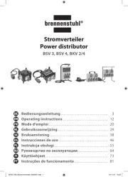
Kategori: | Stikkontakt |
Model: | B760MX2-E |
Har du brug for hjælp?
Hvis du har brug for hjælp til Biostar B760MX2-E stil et spørgsmål nedenfor, og andre brugere vil svare dig
Stikkontakt Biostar Manualer

1 September 2024

30 August 2024

30 August 2024

30 August 2024

30 August 2024

30 August 2024

30 August 2024

30 August 2024

30 August 2024

30 August 2024
Stikkontakt Manualer
- Stikkontakt Ikea
- Stikkontakt Denver
- Stikkontakt CyberPower
- Stikkontakt Hager
- Stikkontakt Silverline
- Stikkontakt Philips
- Stikkontakt Emos
- Stikkontakt Asus
- Stikkontakt Gigabyte
- Stikkontakt Biltema
- Stikkontakt AVM
- Stikkontakt Hama
- Stikkontakt Smartwares
- Stikkontakt Busch-Jaeger
- Stikkontakt Trotec
- Stikkontakt Vivanco
- Stikkontakt Osram
- Stikkontakt Gembird
- Stikkontakt Bose
- Stikkontakt Powerfix
- Stikkontakt Tripp Lite
- Stikkontakt Reer
- Stikkontakt Craftsman
- Stikkontakt Digitus
- Stikkontakt Gamma
- Stikkontakt Niceboy
- Stikkontakt Peerless-AV
- Stikkontakt Schneider
- Stikkontakt Bachmann
- Stikkontakt APC
- Stikkontakt Kathrein
- Stikkontakt Perel
- Stikkontakt JUNG
- Stikkontakt ORNO
- Stikkontakt ECS
- Stikkontakt Brennenstuhl
- Stikkontakt Hazet
- Stikkontakt Manhattan
- Stikkontakt SPC
- Stikkontakt LogiLink
- Stikkontakt Easy Home
- Stikkontakt Kramer
- Stikkontakt Lanberg
- Stikkontakt Anslut
- Stikkontakt Fibaro
- Stikkontakt Panduit
- Stikkontakt Eurolite
- Stikkontakt Vimar
- Stikkontakt Lenoxx
- Stikkontakt InLine
- Stikkontakt Crestron
- Stikkontakt Showtec
- Stikkontakt Kogan
- Stikkontakt Delta
- Stikkontakt Elektrobock
- Stikkontakt Konig & Meyer
- Stikkontakt Neutrik
- Stikkontakt Homematic IP
- Stikkontakt V-TAC
- Stikkontakt Legrand
- Stikkontakt Schwaiger
- Stikkontakt Heitronic
- Stikkontakt Savio
- Stikkontakt PCE
- Stikkontakt Bearware
- Stikkontakt Workzone
- Stikkontakt KlikaanKlikuit
- Stikkontakt Metz
- Stikkontakt AS - Schwabe
- Stikkontakt Duro
- Stikkontakt Gira
- Stikkontakt Peerless
- Stikkontakt Monoprice
- Stikkontakt Berker
- Stikkontakt Extron
- Stikkontakt Leviton
- Stikkontakt Ebode
- Stikkontakt InterBar
- Stikkontakt Pancontrol
- Stikkontakt Phoenix Contact
- Stikkontakt Metz Connect
- Stikkontakt DEHN
- Stikkontakt Omnilux
- Stikkontakt Atlona
- Stikkontakt Hoopzi
- Stikkontakt Hall Research
- Stikkontakt Crydom
- Stikkontakt Adam Hall
- Stikkontakt 360 Electrical
- Stikkontakt PS Audio
- Stikkontakt IOIO
Nyeste Stikkontakt Manualer

12 Januar 2025

10 Januar 2025

10 Januar 2025

3 Januar 2025

30 December 2025

29 December 2024

29 December 2024

29 December 2024

29 December 2024

29 December 2024