Y A K / I BEX O WNERS M A N U A L (800) 893-2447 www.bobgear.com
13501 South Ridge Drive, Charlotte, North Carolina 28273
BOB is a company that produces high quality products, which encourage a healthy, outdoor,
car-free lifestyle. In addition to trailers, we also make full suspension jogging strollers. See
www.bobgear.com for our complete line of products. Before attempting to assemble or use
your new trailer, read and understand these instructions completely to insure proper
assembly and operation. If you are unclear on any point, contact your dealer or BOB before
use.
BOB trailers can be attached to bicycles with wheel sizes between 20" and 28". Please see
the Trailer/Bike Compatibility chart at the end of this manual to determine which trailer is
compatible with your bike. The wheel size appears as a raised surface on the side-wall of the
bicycle tire. If your wheels do not meet these diameter specifications, it is unsafe for you to
attach the trailer. If you have questions about your wheel diameters or trailer compatibility with
your bicycle, consult your bicycle dealer or call us at BOB.
Our trailers are intended to carry cargo only.
Do not carry children or live animals.
Cargo capacity: 70 pounds (32 kilograms)
The more weight you add to the trailer, (just like a car) the more effect it will have on the
handling of your bicycle.
All cargo must be securely fastened to the trailer frame. Shifting loads can adversely affect
bicycle handling and result in loss of control.
Keep the cargo center of gravity low.
The load height above the mesh platform should never exceed 18 inches (46cm). Loads
higher than 18" can adversely affect bicycle handling and result in loss of control.
QR length must be correctly sized to your specific bicycle to insure safe operation.
Make sure your bike's brakes are in top condition and properly adjusted. Always allow extra
stopping distance when riding with your trailer. Marginally performing brakes will be inadequate
for safe braking with the added load of a trailer. When riding in wet conditions use extreme
caution and allow even more distance for braking.
Generally, car drivers don't expect bicycles to be pulling trailers. Use the included BOB
safety flag to be seen!
When passing another cyclist, remember that you are approximately 4.5 feet (140cm) longer
than your bike alone!
The YAK & IBEX come with wheel and fender reflectors for night visibility. Check that the
reflectors on both your bicycle and trailer are properly installed. Installation procedures follow
in this manual. Contact your appropriate state government office to learn of the lighting
requirements for your state / country.
SPEED LIMIT: 25 mph (40 kph) A bike with trailer attached, steers and feels different.
Ride cautiously. Speed wobbles (and loss of control) can occur if speed limit is exceeded.
It is CRITICAL that the wheels and tires of your bicycle and trailer are properly maintained
(see your bike dealer) and inflated to the normal operating pressure embossed on the sidewall.
Some full suspension bicycles and rear suspension recumbents do not have adequate frame
stiffness to offset the forces of a fully loaded, moving trailer. The result can be a bike that is
sluggish, difficult to control or stop which could lead to a crash (and/or damage to the trailer
or contents). We strongly recommend test riding (braking and turning) the bike with a full,
non-human, test load [70 lbs (32kgs)] in a cautious manner (in an area absent of traffic hazards)
to determine if this condition exists. This condition could be exacerbated by wet, sandy, or
gravel covered surfaces.
Some variables that can affect the control of your bike and trailer: improper installation of
BOB QR / improper installation of trailer fork retaining pins to BOB QR / improper installation
of trailer fork to YAK & IBEX frame / road conditions / wind speed and direction / cyclist's skill
level / weight of rider relative to the amount of weight in trailer / center of gravity of cargo /
integrity of all wheels (proper spoke tension and bearing adjustment)
Rear racks and panniers are sometimes used in conjunction with the trailers. With some
frames (usually smaller sizes) it is possible for the bottom of the pannier to come in contact
with the top of the retention pin. This can cause the pin to release resulting in the unexpected
detachment of the trailer. This can lead to loss of control and injury. Make certain that this
condition does not exist. If it appears to be a problem, using our older style pin (PI9500) may
eliminate this problem.
Attach and detach the trailer ONLY when it is in a straight line with the bike. You can bend
the fork otherwise. It is easiest to attach and detach trailer when it is unloaded.
Protect all sharp objects from puncturing DRY SAK.
The YAK & IBEX forks must be limited to approximately 20 degrees of rotation to avoid
contacting the rear derailleur and possibly bending the mount. (FIG. 2). This can happen
when riding over large, fallen trees, lifting the bike and trailer, or possibly when utilizing the
"park mode" feature (Fig. 31). Check the amount of clearance your bike's derailleur has before
riding.
This box/package should contain the following parts; check to make sure before starting to
assemble; if there are parts missing or you need replacement parts please call customer
service M-F 8:30 am -5 pm MST at 208-375-5171 or 800-893-2447. Do not use any substitute
non-original parts as this may lead to premature failure of the product.
Before proceeding with the trailer assembly and installation, you should confirm your
bike and trailer are compatible with one another. Reference the Trailer/Bike Compatibility
chart at the end of this manual.
BOB Quick Release or BOB Nutz ...what do you need?
Most modern bicycles use a quick release mechanism (QR) to secure wheels to the bicycle.
The YAK & IBEX trailers are attached to the bicycle with a specially designed BOB QR. The
BOB QR replaces the bikes original rear QR, and has a trailer attachment point on both ends.
We make our QRs in three lengths (standard, 145mm (tandem), and Santana/160mm). If
your bike does not use a QR to hold on the rear wheel, you will need a pair of BOB Nutz. BOB
Nutz and Quick Release specifications are listed at
end of manual.
NOTE: BOB TRAILERS INC. IS NOT RESPONSIBLE
FOR INJURY, DAMAGE, OR FAILURE THAT
RESULTS FROM FAULTY ASSEMBLY OR
MAINTENANCE AFTER RECEIPT OF PRODUCT.
1. UNPACK: Remove trailer, small
parts box and box contents, Dry
SAK, etc. Plastic packaging
material was used to protect the
rear dropouts and the wheel axles.
Remove these plastic pieces as
well as all other packaging material.
2. FORK ASSEMBLY: For shipping
purposes, the trailer fork has been
attached to the frame pointing to the rear of the trailer, Fig. 3. The fork
will need to be removed and rotated 180 degrees, and then reattached
prior to use, as shown in Fig 4.
A) Remove the lock nut (Fig. 3, using two 10mm wrenches) and flat washer
then fully remove the long 6mm bolt. This will free the fork from the
trailer frame. Remove the fork. To reinstall the fork pointing forward,
align the holes in the pivot plates of the trailer frame and the pivot
tube in the fork as shown in Fig. 4.
B) Insert the long 6mm bolt with a washer on each end then
tighten the lock nut, Fig. 4. Tighten the lock nut to 60 inch
pounds (70 cm-kgs).
3. SWING ARM INSTALLATION :(IBEX ONLY)
A) Begin by first removing the pivot bolt and washers,
Fig. 1, using two 10mm wrenches.
B) Next install the swingarm pivot in the shock tower.
The pivot is wider than the shock tower opening and
will need to be twisted so the left bushing/side of the swingarm goes through the opening first
and exits the left side window as shown in Fig. 5.
C) To get the right side bushing inside the tower, align it with the upper right hand corner of
the tower opening as shown in Fig. 6 and rotate forward. The pivot should now be inside the
shock tower. You will install the pivot bolt after installing the upper shock bolt.
D) Remove the upper shock axle, Fig. 1. Align the shock axle with the holes in the shock tower
and install the axle and washer, Fig. 7, and tighten to 60 inch-pounds (70 cm-kgs) using two
5mm Allen wrenches.
E) The pivot axle will need to be aligned with the pivot bolt holes in the shock tower. These
are located above and forward of the windows in the sides of the tower. The fit between the
pivot axle and tower is a tight tolerance fit so it will take some effort to move the pivot into
position. This can be done by pushing on the back of the swingarm and rotating the pivot axle
into alignment with the pivot bolt holes as
shown in Fig. 8. Once aligned, install pivot bolt
and washers, Fig. 8, and tighten to 60 inch-
pounds (70 cm-kgs) using two 10mm wrenches.
4. FENDER ASSEMBLY :(YAK ONLY)
A) Fender Reflector Installation - The fender
reflector attaches to the rear portion of the
fender. The reflector has a threaded stud built
into it. Attach the reflector to the fender by
inserting the stud into the upper hole and the
plastic "alignment pin" into the lower hole of
the fender as shown in Fig. 9. Next, place the
washer over the portion of the stud extending
through the underside of the fender. Thread
the nut on and tighten with an 8mm wrench.
B) Fender Bracket Attachment - First, attach
the fender bracket to the fender. Place the
fender bracket in the center of the two holes
in the fender and align the mounting hardware
with them as shown in Fig. 10. Insert the screws
through the holes from the outside of the fender.
Place the threaded backing plate on the inside
of the fender and tighten the screws using a
screwdriver.
C) Fender Attachment - The fender attaches
to the trailer in three places. Begin by removing
the screw and washers from the forward fender
mount on the trailer frame. Attach the fender
to the trailer by inserting the bolt and washer
through the slot in the fender. Next place the
second washer behind it (sandwiching the
fender with washers) as shown in Fig. 11.
Tighten the bolt securely with a 4mm Allen
wrench. Next, attach the fender brackets to
the left and right dropouts. Insert the bolt
through the washer and then through the loop
in the fender bracket as shown in Fig. 12. Align
the bolt with the eyelet in the dropout and
tighten securely with a 4mm Allen wrench.
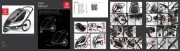
B O X C O N T E N T S
FIG.6
Right Bushing aligned with upper
right shock tower opening.
Right
Bushing
FIG.5
Left Bushing through shock
tower opening and left window.
Left
Bushing
Through
Window
W A R N I N G S
c a U T I O N
Trailer Anatomy (YAK & IBEX).
FIG.1
Tire
FIG.2
Trailer in extreme counter-clockwise
rotation showing contact between
derailleur pivot housing and trailer fork.
AVOID this condition. If you believe this
has occurred, inspect your derailleur, QR,
and pins for damage.
Trailer Wheel QR
Flag with Flag Pole
Spare Attachment Pin
Bungee Cord
Owner's Manual
Dry Sak (YAK Plus & IBEX Plus only)
Fork/Frame Assembly
Swing Arm/Shock Assembly (IBEX only)
Fender, Fender Reflector,
& mounting hardware (YAK only)
Wheel Reflectors
BOB QR
Trailer Wheel
For some older bikes with
dropout spacing below 135mm:
Metal cutting saw
Metric die or nut; 5mm x .8mm
Metal file
Tools Needed:
Two 4mm hex wrenches (allen wrenches)
Two 10mm wrenches (or adjustable wrenches)
8 mm wrench (YAK only)
Phillips screwdriver (YAK only)
Slotted screwdriver
A S S E M B LY I N S TRUCTI O N S
FIG.3 Fork Rotated To Rear.
6mm bolt
Locknut &
Washer
FIG.4 Rotated Fork & Bolt Assembly.
Pivot
Plate
Pivot Tube
6mm
Bolt
Washer
Locknut
Shock Tower
Pivot Bolt
Upper Shock
Axle
BOB QR
Fork
Pivot Bolt
Pivot Plate
Rail Tie
Upper Rail
Cargo
Stop
Flag
Fender
Fender
Reflector
Wheel
Reflector
Fender
Bracket
Wheel Quick
Release
Rim
Wheel
Dropout
Lower
Rail
Skid
Cargo
Platform
Pivot
Tube
Hook
Pin Bungee
Hook
All items same as YAK
except those noted
1
OMT01C