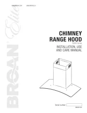
Bosch DIA 106750 Manual
Læs gratis den danske manual til Bosch DIA 106750 (108 sider) i kategorien Emhætte. Denne vejledning er vurderet som hjælpsom af 50 personer og har en gennemsnitlig bedømmelse på 4.4 stjerner ud af 25.5 anmeldelser.
Har du et spørgsmål om Bosch DIA 106750, eller vil du spørge andre brugere om produktet?

Produkt Specifikationer
| Mærke: | Bosch |
| Kategori: | Emhætte |
| Model: | DIA 106750 |
Har du brug for hjælp?
Hvis du har brug for hjælp til Bosch DIA 106750 stil et spørgsmål nedenfor, og andre brugere vil svare dig
Emhætte Bosch Manualer

Emhætte Manualer
- Teka
- Cobal
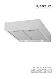
- Artusi
- ZLine
- Sam Cook
- Porter & Charles
- Thomson
- InAlto
- Heinner
- Fors
- Scancool
- Whirlpool
- Globalo
- KitchenAid
- Vestel
Nyeste Emhætte Manualer