OMNI-5
RED/GREEN LOW PROFILE SIGHT INSTRUCTIONS
CAUTION: BEFORE YOU BEGIN, ENSURE THAT THE FIREARM IS CLEAR. REMOVE MAGAZINE,
LOCK ACTION OPEN AND VISUALLY INSPECT TO ENSURE THAT THE CHAMBER IS CLEAR.
PRODUCT SPECIFICATIONS
POWERING UP AND POWERING DOWN THE RED DOT
Depress and release the “+” or “-” button to power up the red dot; press “+” and “-” button
to power down the red dot. Press “C” to change color between red and green. This red dot
has a convenient auto-off feature that will switch off the device if it has been left on for
more than 4 hours. If the unit shuts down automatically, moving or lifting the gun will turn
the unit on again automatically. However, if the unit is turned off by pressing “+” and “-”
simultaneously, the unit will not be turned on automatically by moving or lifting the gun.
ADJUSTING BRIGHTNESS
Press the “+” or “-” button and select the lowest brightness setting that still provides good
contrast against the target. The higher brightness settings should only be used in bright
daylight (otherwise, the reticle may appear distorted).
BATTERY
Your sight includes a 3-volt lithium battery (CR2032). To replace the battery, rotate the
battery cover counter-clockwise and remove. Insert the replacement battery with “+” side
facing out. Replace the cover and hand-tighten.
INSTALLATION
CAUTION: BEFORE YOU BEGIN, ENSURE THAT THE FIREARM IS CLEAR. REMOVE MAGAZINE,
LOCK ACTION OPEN AND VISUALLY INSPECT TO ENSURE THAT THE CHAMBER IS CLEAR.
To get the best performance from your red dot, it must be mounted properly. If you are not
familiar with mounting a red dot, it is strongly recommended that you seek the assistance of
a qualied professional.
MOUNT ONTO A PICATINNY OR WEAVERSTYLE RAIL
Your sight has integrated mounting rails that attach to a standard Weaver-style base or
Picatinny rail.
Loosen both mounting screws and set the sight onto the mounting base of the rearm.
Please note that one mounting screw is lower than the other mounting screw. Only the
lower mounting screw should t into one of the grooves in the top of the mounting base.
Be sure the sight is fully seated on the mounting base before tightening the mounting
screws. To ensure tightening, alternate between screws after each half turn.
( DO NOT OVER TIGHTEN MOUNTING HARDWARE. MAX. TORQUE 20 INCH LBS. )
For additional security, a drop of thread-locker can be added to the mounting screws.
PARALLAX
Your sight has been carefully set to have a minimum parallax at 30 yards. At distances
signicantly greater or less than this distance, some parallax will be observed. To reduce the
possibility of a Point if Impact (POI) shift caused by parallax, the reticle should be kept in the
middle 2/3 of the eld of view when aiming.
ZEROING
Initial Setup
The dot position has been pre-set at the factory. Only minor windage and elevation
adjustments should be required. If possible, a bore sighting device should be used for rough
alignment of the sight to the rearm. If bore sighting is not possible, place the rearm on
a sturdy rest and look through the barrel or along the rail at a small target about 25 yards
away. Turn on the red dot and select a suitable brightness. Using a straight-slot screwdriver,
adjust the windage and elevation until the dot position corresponds with the target. Note
the following when making adjustments.
Click value: 1 MOA (approximately 1” at 100 yards; ¼” at 25 yards)
Windage: Counterclockwise (indicated by arrow) moves point of impact right/clockwise, left.
Elevation: Counterclockwise (indicated by arrow) moves point of impact up/clockwise, down.
FINAL SETUP (LIVE FIRE)
CAUTION: USE ADEQUATE EYE AND EAR PROTECTION AT ALL TIMES. SHOOT ONLY AT AN
APPROVED RANGE OR SUITABLE SAFE AREA.
CAUTION: IF YOU HAVE USED A BORE SIGHTER, CONFIRM THAT THE BORE SPUD IS NO
LONGER IN THE MUZZLE AND THAT THE BORE IS UNOBSTRUCTED.
Position the target no further than 25 yards away to begin the zeroing process. Turn on
the red dot and select a suitable brightness. Carefully re three shots and note where they
strike on the target. Your group should strike the target no greater than 10” from your point
of aim. (Should the group be farther away than this, the mounting process is faulty and
must be corrected before proceeding.) Make adjustments to windage and elevation so that
your group strikes the target approximately 1” beneath the point of aim with no windage
error (at six o’clock, neither left nor right).
When complete, position the target at the desired zero distance. Fire three rounds at this
distance and adjust as necessary to hit dead-on.
RETICLE
Your sight uses a 2 MOA reticle pattern. One MOA is about 1” at a distance of 100 yards (or
3/4” at 75 yards, 1/2” inch at 50 yards, etc.).
FLIP-UP LENS CAPS
This model includes flip-up lens caps. These lens caps are intended to protect the optical
glass from inclement weather and dust. While impervious to many chemicals, care should be
taken to avoid contact with powerful solvents and chemicals.
MIRROR ANGLE
The mirror-lens can be easily seen when looking through the wrong end of the sight. The tilt
of the mirror-lens is not a defect. It is tilted to reflect the LED’s light back to the user’s eye.
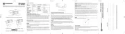
The OMNI-5 red dot sight may be mounted in two congurations:
LOW PROFILE MOUNT HIGH CO-WITNESS MOUNT
CAUTION: BEFORE YOU BEGIN, ENSURE THAT THE FIREARM IS CLEAR. REMOVE
MAGAZINE, LOCK ACTION OPEN AND VISUALLY INSPECT TO ENSURE THAT THE CHAMBER
IS CLEAR.
The OMNI-5 red dot sight may be mounted in two configuraons:
PRODUCT SPECIFICATIONS
Model OMNI-5
Descripon RED/GREEN LOW PROFILE SIGHT
Magnificaon 1x
Length 4.8"
Width 2.4"
Height (low / high) 2.3" / 2.8"
Opcal height (low / high) 1.1" / 1.4"
Weight (low / high) 0.7 LBS / 0.75 LBS
Power Supply CR2032 3V Lithium Baery
Range of Adjustment
Windage 40 MOA
Elevaon 40 MOA
Click Value 1 MOA
Accessories
Picanny Mount
4 Mounng Screws
2mm Hex Wrench
3mm Hex Wrench
POWERING UP AND ADJUSTING DOT BRIGHTNESS
Powering Up and Powering Down the Red Dot
Depress and release the "+" or "-" buon to power up the red dot; press "+" and "-"
buon to power down the red dot. Press “C” to change color between red and green.
This red dot has a convenient auto-off feature that will switch off the device if it has been
le on for more than 4 hours. If the unit shuts down automacally, moving or liing the
gun will turn the unit on again automacally. However, if the unit is turned off by
pressing "+" and "-" simultaneously, the unit will not be turned on automacally by
moving or liing the gun.
Adjusng Brightness
Press the "+" or "-" buon and select the lowest brightness seng that sll provides
good contrast against the target. The higher brightness sengs should only be used in
bright daylight (otherwise, the recle may appear distorted).
Baery
Your sight includes a 3-volt lithium baery (CR2032). To replace the baery, rotate the
baery cover counter-clockwise and remove. Insert the replacement baery with “+” side
facing out. Replace the cover and hand-ghten.
INSTALLATION
CAUTION: BEFORE YOU BEGIN, ENSURE THAT THE FIREARM IS CLEAR. REMOVE
MAGAZINE, LOCK ACTION OPEN AND VISUALLY INSPECT TO ENSURE THAT THE CHAMBER
IS CLEAR.
To get the best performance from your red dot, it must be mounted properly. If you are
not familiar with mounng a red dot, it is strongly recommended that you seek the
assistance of a qualified professional.
Mount onto a Picanny or Weaver-style rail
Your sight has integrated mounng rails that aach to a standard Weaver-style base or
Picanny rail.
Loosen both mounng screws and set the sight onto the mounng base of the firearm.
Please note that one mounng screw is lower than the other mounng screw. Only the
lower mounng screw should fit into one of the grooves in the top of the mounng base.
Be sure the sight is fully seated on the mounng base before ghtening the mounng
screws. To ensure ghtening, alternate between screws aer each half turn. (DO NOT
OVER TIGHTEN MOUNTING HARDWARE. MAX. TORQUE 20 INCH LBS.) For addional
security, a drop of thread-locker can be added to the mounng screws.
PARALLAX
Your sight has been carefully set to have a minimum parallax at 30 yards. At distances
significantly greater or less than this distance, some parallax will be observed. To reduce
the possibility of a Point if Impact (POI) shi caused by parallax, the recle should be kept
in the middle 2/3 of the field of view when aiming.
ZEROING
Inial Setup
The dot posion has been pre-set at the factory. Only minor windage and elevaon
adjustments should be required. If possible, a bore sighng device should be used for
rough alignment of the sight to the firearm. If bore sighng is not possible, place the
firearm on a sturdy rest and look through the barrel or along the rail at a small target
about 25 yards away. Turn on the red dot and select a suitable brightness. Using a
straight-slot screwdriver, adjust the windage and elevaon unl the dot posion
corresponds with the target. Note the following when making adjustments.
Click value: 1 MOA (approximately 1" at 100 yards; ¼” at 25 yards)
Windage: Counterclockwise (indicated by arrow) moves point of impact right/clockwise,
le.
Elevaon: Counterclockwise (indicated by arrow) moves point of impact up/clockwise,
down.
Final Setup (Live Fire)
CAUTION: USE ADEQUATE EYE AND EAR PROTECTION AT ALL TIMES. SHOOT ONLY AT AN
APPROVED RANGE OR SUITABLE SAFE AREA.
CAUTION: IF YOU HAVE USED A BORE SIGHTER, CONFIRM THAT THE BORE SPUD IS NO
LONGER IN THE MUZZLE AND THAT THE BORE IS UNOBSTRUCTED.
Posion the target no further than 25 yards away to begin the zeroing process. Turn on
the red dot and select a suitable brightness. Carefully fire three shots and note where
they strike on the target. Your group should strike the target no greater than 10" from
your point of aim. (Should the group be farther away than this, the mounng process is
faulty and must be corrected before proceeding.) Make adjustments to windage and
elevaon so that your group strikes the target approximately 1" beneath the point of aim
with no windage error (at six o’clock, neither le nor right).
When complete, posion the target at the desired zero distance. Fire three rounds at this
distance and adjust as necessary to hit dead-on.
RETICLE
Your sight uses a 2 MOA recle paern.
One MOA is about 1” at a distance of 100 yards (or 3/4” at 75 yards, 1/2” inch at 50 yards,
etc.).
FLIP-UP LENS CAPS
This model includes flip-up lens caps. These lens caps are intended to protect the opcal
glass from inclement weather and dust. While impervious to many chemicals, care
should be taken to avoid contact with powerful solvents and chemicals.
MIRROR ANGLE
The mirror-lens can be easily seen when looking through the wrong end of the sight. The
lt of the mirror-lens is not a defect. It is lted to reflect the LED’s light back to the user’s
eye.
MAINTENANCE & CLEANING
Although your red dot is extremely durable, it is a precision instrument that should be
treated with reasonable care.
Lenses
The opcal coangs are hard and will last indefinitely with proper care.
Should either protecve windows become dirty, blow loose materials off before cleaning.
Use lens cleaning fluid and a so cloth to dab at the surface and remove any abrasive bits
of dust and dirt before applying more pressure. Be paent and clean in steps so as to not
grind abrasive dirt into the lens.
Exterior
Should the exterior become dirty, it may be cleaned with a damp cloth. Do not use oil or
solvents as they may be harmful if inadvertently rubbed onto the opcal coangs.
STORAGE
This red dot has been constructed using adhesives and lubricants that enable a broad
range of operaonal and storage environments. The grease used is temperature-stable
from -50 to +175 degrees Fahrenheit. Do not store at temperatures outside this range
(for example a car trunk on a very hot day).
TROUBLESHOOTING
Please use the following guide to test/correct operaonal issues with this red dot.
1. Red dot will not power up.
A. Check to see that the baery is properly installed with “+” side facing down.
B. Replace baery.
C. Inspect baery terminals for corrosion or debris inhibing contact and correct as
necessary.
D. Should the above be ineffecve in resolving the problem, contact Bresser (add
appropriate contact info here) for return procedures.
2. Red dot brightness will not adjust.
A. Move to where ambient light is low enough to clearly discern a change in brightness.
B. Follow fault diagnosis #1A-C above and repeat 2A. If brightness will not adjust, contact
Bresser (add appropriate contact info here) for return procedures.
3. Red dot will not zero.
Review secons of this manual regarding zeroing. This red dot is pre-centered at the
factory; if more than 10" of adjustment is required at a sight-in distance of 25 yards,
mounng is at fault.
4.Red dot will not adjust for windage and/or elevaon
This red dot has a maximum adjustment range of 30 MOA. Beyond this range of
adjustment, rotang the W/E screws will not provide addional point of impact change.
If you believe that your red dot is within the maximum range of adjustment and not
providing W/E movement, contact Bresser (add appropriate contact info here) for return
procedures.
5. Red dot appearance and/or target is not clear.
A. Be sure to select the lowest brightness seng that sll provides good contrast against
the target; using too high a seng may make the recle appear distorted.
B. Inspect both sides of the main lens for contaminaon and clean as necessary. (See
MAINTENANCE & CLEANING in this manual.)
C. Inspect the protecve window in front of the diode and clean as necessary. (See
MAINTENANCE & CLEANING in this manual.)
D. Should the above be ineffecve in resolving the problem, contact Bresser ( add
appropriate contact info here ) ( for return procedures.
LIFETIME LIMITED WARRANTY
JOC warranty.
Flip Up Cap
Flip Up Cap
Mounng Screws
Baery Cover
Elevaon Adjustment
Windage Adjustment
Power/Brightness
Control
CAUTION: BEFORE YOU BEGIN, ENSURE THAT THE FIREARM IS CLEAR. REMOVE
MAGAZINE, LOCK ACTION OPEN AND VISUALLY INSPECT TO ENSURE THAT THE CHAMBER
IS CLEAR.
The OMNI-5 red dot sight may be mounted in two configuraons:
PRODUCT SPECIFICATIONS
Model OMNI-5
Descripon RED/GREEN LOW PROFILE SIGHT
Magnificaon 1x
Length 4.8"
Width 2.4"
Height (low / high) 2.3" / 2.8"
Opcal height (low / high) 1.1" / 1.4"
Weight (low / high) 0.7 LBS / 0.75 LBS
Power Supply CR2032 3V Lithium Baery
Range of Adjustment
Windage 40 MOA
Elevaon 40 MOA
Click Value 1 MOA
Accessories
Picanny Mount
4 Mounng Screws
2mm Hex Wrench
3mm Hex Wrench
POWERING UP AND ADJUSTING DOT BRIGHTNESS
Powering Up and Powering Down the Red Dot
Depress and release the "+" or "-" buon to power up the red dot; press "+" and "-"
buon to power down the red dot. Press “C” to change color between red and green.
This red dot has a convenient auto-off feature that will switch off the device if it has been
le on for more than 4 hours. If the unit shuts down automacally, moving or liing the
gun will turn the unit on again automacally. However, if the unit is turned off by
pressing "+" and "-" simultaneously, the unit will not be turned on automacally by
moving or liing the gun.
Adjusng Brightness
Press the "+" or "-" buon and select the lowest brightness seng that sll provides
good contrast against the target. The higher brightness sengs should only be used in
bright daylight (otherwise, the recle may appear distorted).
Baery
Your sight includes a 3-volt lithium baery (CR2032). To replace the baery, rotate the
baery cover counter-clockwise and remove. Insert the replacement baery with “+” side
facing out. Replace the cover and hand-ghten.
INSTALLATION
CAUTION: BEFORE YOU BEGIN, ENSURE THAT THE FIREARM IS CLEAR. REMOVE
MAGAZINE, LOCK ACTION OPEN AND VISUALLY INSPECT TO ENSURE THAT THE CHAMBER
IS CLEAR.
To get the best performance from your red dot, it must be mounted properly. If you are
not familiar with mounng a red dot, it is strongly recommended that you seek the
assistance of a qualified professional.
Mount onto a Picanny or Weaver-style rail
Your sight has integrated mounng rails that aach to a standard Weaver-style base or
Picanny rail.
Loosen both mounng screws and set the sight onto the mounng base of the firearm.
Please note that one mounng screw is lower than the other mounng screw. Only the
lower mounng screw should fit into one of the grooves in the top of the mounng base.
Be sure the sight is fully seated on the mounng base before ghtening the mounng
screws. To ensure ghtening, alternate between screws aer each half turn. (DO NOT
OVER TIGHTEN MOUNTING HARDWARE. MAX. TORQUE 20 INCH LBS.) For addional
security, a drop of thread-locker can be added to the mounng screws.
PARALLAX
Your sight has been carefully set to have a minimum parallax at 30 yards. At distances
significantly greater or less than this distance, some parallax will be observed. To reduce
the possibility of a Point if Impact (POI) shi caused by parallax, the recle should be kept
in the middle 2/3 of the field of view when aiming.
ZEROING
Inial Setup
The dot posion has been pre-set at the factory. Only minor windage and elevaon
adjustments should be required. If possible, a bore sighng device should be used for
rough alignment of the sight to the firearm. If bore sighng is not possible, place the
firearm on a sturdy rest and look through the barrel or along the rail at a small target
about 25 yards away. Turn on the red dot and select a suitable brightness. Using a
straight-slot screwdriver, adjust the windage and elevaon unl the dot posion
corresponds with the target. Note the following when making adjustments.
Click value: 1 MOA (approximately 1" at 100 yards; ¼” at 25 yards)
Windage: Counterclockwise (indicated by arrow) moves point of impact right/clockwise,
le.
Elevaon: Counterclockwise (indicated by arrow) moves point of impact up/clockwise,
down.
Final Setup (Live Fire)
CAUTION: USE ADEQUATE EYE AND EAR PROTECTION AT ALL TIMES. SHOOT ONLY AT AN
APPROVED RANGE OR SUITABLE SAFE AREA.
CAUTION: IF YOU HAVE USED A BORE SIGHTER, CONFIRM THAT THE BORE SPUD IS NO
LONGER IN THE MUZZLE AND THAT THE BORE IS UNOBSTRUCTED.
Posion the target no further than 25 yards away to begin the zeroing process. Turn on
the red dot and select a suitable brightness. Carefully fire three shots and note where
they strike on the target. Your group should strike the target no greater than 10" from
your point of aim. (Should the group be farther away than this, the mounng process is
faulty and must be corrected before proceeding.) Make adjustments to windage and
elevaon so that your group strikes the target approximately 1" beneath the point of aim
with no windage error (at six o’clock, neither le nor right).
When complete, posion the target at the desired zero distance. Fire three rounds at this
distance and adjust as necessary to hit dead-on.
RETICLE
Your sight uses a 2 MOA recle paern.
One MOA is about 1” at a distance of 100 yards (or 3/4” at 75 yards, 1/2” inch at 50 yards,
etc.).
FLIP-UP LENS CAPS
This model includes flip-up lens caps. These lens caps are intended to protect the opcal
glass from inclement weather and dust. While impervious to many chemicals, care
should be taken to avoid contact with powerful solvents and chemicals.
MIRROR ANGLE
The mirror-lens can be easily seen when looking through the wrong end of the sight. The
lt of the mirror-lens is not a defect. It is lted to reflect the LED’s light back to the user’s
eye.
MAINTENANCE & CLEANING
Although your red dot is extremely durable, it is a precision instrument that should be
treated with reasonable care.
Lenses
The opcal coangs are hard and will last indefinitely with proper care.
Should either protecve windows become dirty, blow loose materials off before cleaning.
Use lens cleaning fluid and a so cloth to dab at the surface and remove any abrasive bits
of dust and dirt before applying more pressure. Be paent and clean in steps so as to not
grind abrasive dirt into the lens.
Exterior
Should the exterior become dirty, it may be cleaned with a damp cloth. Do not use oil or
solvents as they may be harmful if inadvertently rubbed onto the opcal coangs.
STORAGE
This red dot has been constructed using adhesives and lubricants that enable a broad
range of operaonal and storage environments. The grease used is temperature-stable
from -50 to +175 degrees Fahrenheit. Do not store at temperatures outside this range
(for example a car trunk on a very hot day).
TROUBLESHOOTING
Please use the following guide to test/correct operaonal issues with this red dot.
1. Red dot will not power up.
A. Check to see that the baery is properly installed with “+” side facing down.
B. Replace baery.
C. Inspect baery terminals for corrosion or debris inhibing contact and correct as
necessary.
D. Should the above be ineffecve in resolving the problem, contact Bresser (add
appropriate contact info here) for return procedures.
2. Red dot brightness will not adjust.
A. Move to where ambient light is low enough to clearly discern a change in brightness.
B. Follow fault diagnosis #1A-C above and repeat 2A. If brightness will not adjust, contact
Bresser (add appropriate contact info here) for return procedures.
3. Red dot will not zero.
Review secons of this manual regarding zeroing. This red dot is pre-centered at the
factory; if more than 10" of adjustment is required at a sight-in distance of 25 yards,
mounng is at fault.
4.Red dot will not adjust for windage and/or elevaon
This red dot has a maximum adjustment range of 30 MOA. Beyond this range of
adjustment, rotang the W/E screws will not provide addional point of impact change.
If you believe that your red dot is within the maximum range of adjustment and not
providing W/E movement, contact Bresser (add appropriate contact info here) for return
procedures.
5. Red dot appearance and/or target is not clear.
A. Be sure to select the lowest brightness seng that sll provides good contrast against
the target; using too high a seng may make the recle appear distorted.
B. Inspect both sides of the main lens for contaminaon and clean as necessary. (See
MAINTENANCE & CLEANING in this manual.)
C. Inspect the protecve window in front of the diode and clean as necessary. (See
MAINTENANCE & CLEANING in this manual.)
D. Should the above be ineffecve in resolving the problem, contact Bresser ( add
appropriate contact info here ) ( for return procedures.
LIFETIME LIMITED WARRANTY
JOC warranty.
Flip Up Cap
Flip Up Cap
Mounng Screws
Baery Cover
Elevaon Adjustment
Windage Adjustment
Power/Brightness
Control
2 MOA
CAUTION: BEFORE YOU BEGIN, ENSURE THAT THE FIREARM IS CLEAR. REMOVE
MAGAZINE, LOCK ACTION OPEN AND VISUALLY INSPECT TO ENSURE THAT THE CHAMBER
IS CLEAR.
The OMNI-5 red dot sight may be mounted in two configuraons:
PRODUCT SPECIFICATIONS
Model OMNI-5
Descripon RED/GREEN LOW PROFILE SIGHT
Magnificaon 1x
Length 4.8"
Width 2.4"
Height (low / high) 2.3" / 2.8"
Opcal height (low / high) 1.1" / 1.4"
Weight (low / high) 0.7 LBS / 0.75 LBS
Power Supply CR2032 3V Lithium Baery
Range of Adjustment
Windage 40 MOA
Elevaon 40 MOA
Click Value 1 MOA
Accessories
Picanny Mount
4 Mounng Screws
2mm Hex Wrench
3mm Hex Wrench
POWERING UP AND ADJUSTING DOT BRIGHTNESS
Powering Up and Powering Down the Red Dot
Depress and release the "+" or "-" buon to power up the red dot; press "+" and "-"
buon to power down the red dot. Press “C” to change color between red and green.
This red dot has a convenient auto-off feature that will switch off the device if it has been
le on for more than 4 hours. If the unit shuts down automacally, moving or liing the
gun will turn the unit on again automacally. However, if the unit is turned off by
pressing "+" and "-" simultaneously, the unit will not be turned on automacally by
moving or liing the gun.
Adjusng Brightness
Press the "+" or "-" buon and select the lowest brightness seng that sll provides
good contrast against the target. The higher brightness sengs should only be used in
bright daylight (otherwise, the recle may appear distorted).
Baery
Your sight includes a 3-volt lithium baery (CR2032). To replace the baery, rotate the
baery cover counter-clockwise and remove. Insert the replacement baery with “+” side
facing out. Replace the cover and hand-ghten.
INSTALLATION
CAUTION: BEFORE YOU BEGIN, ENSURE THAT THE FIREARM IS CLEAR. REMOVE
MAGAZINE, LOCK ACTION OPEN AND VISUALLY INSPECT TO ENSURE THAT THE CHAMBER
IS CLEAR.
To get the best performance from your red dot, it must be mounted properly. If you are
not familiar with mounng a red dot, it is strongly recommended that you seek the
assistance of a qualified professional.
Mount onto a Picanny or Weaver-style rail
Your sight has integrated mounng rails that aach to a standard Weaver-style base or
Picanny rail.
Loosen both mounng screws and set the sight onto the mounng base of the firearm.
Please note that one mounng screw is lower than the other mounng screw. Only the
lower mounng screw should fit into one of the grooves in the top of the mounng base.
Be sure the sight is fully seated on the mounng base before ghtening the mounng
screws. To ensure ghtening, alternate between screws aer each half turn. (DO NOT
OVER TIGHTEN MOUNTING HARDWARE. MAX. TORQUE 20 INCH LBS.) For addional
security, a drop of thread-locker can be added to the mounng screws.
PARALLAX
Your sight has been carefully set to have a minimum parallax at 30 yards. At distances
significantly greater or less than this distance, some parallax will be observed. To reduce
the possibility of a Point if Impact (POI) shi caused by parallax, the recle should be kept
in the middle 2/3 of the field of view when aiming.
ZEROING
Inial Setup
The dot posion has been pre-set at the factory. Only minor windage and elevaon
adjustments should be required. If possible, a bore sighng device should be used for
rough alignment of the sight to the firearm. If bore sighng is not possible, place the
firearm on a sturdy rest and look through the barrel or along the rail at a small target
about 25 yards away. Turn on the red dot and select a suitable brightness. Using a
straight-slot screwdriver, adjust the windage and elevaon unl the dot posion
corresponds with the target. Note the following when making adjustments.
Click value: 1 MOA (approximately 1" at 100 yards; ¼” at 25 yards)
Windage: Counterclockwise (indicated by arrow) moves point of impact right/clockwise,
le.
Elevaon: Counterclockwise (indicated by arrow) moves point of impact up/clockwise,
down.
Final Setup (Live Fire)
CAUTION: USE ADEQUATE EYE AND EAR PROTECTION AT ALL TIMES. SHOOT ONLY AT AN
APPROVED RANGE OR SUITABLE SAFE AREA.
CAUTION: IF YOU HAVE USED A BORE SIGHTER, CONFIRM THAT THE BORE SPUD IS NO
LONGER IN THE MUZZLE AND THAT THE BORE IS UNOBSTRUCTED.
Posion the target no further than 25 yards away to begin the zeroing process. Turn on
the red dot and select a suitable brightness. Carefully fire three shots and note where
they strike on the target. Your group should strike the target no greater than 10" from
your point of aim. (Should the group be farther away than this, the mounng process is
faulty and must be corrected before proceeding.) Make adjustments to windage and
elevaon so that your group strikes the target approximately 1" beneath the point of aim
with no windage error (at six o’clock, neither le nor right).
When complete, posion the target at the desired zero distance. Fire three rounds at this
distance and adjust as necessary to hit dead-on.
RETICLE
Your sight uses a 2 MOA recle paern.
One MOA is about 1” at a distance of 100 yards (or 3/4” at 75 yards, 1/2” inch at 50 yards,
etc.).
FLIP-UP LENS CAPS
This model includes flip-up lens caps. These lens caps are intended to protect the opcal
glass from inclement weather and dust. While impervious to many chemicals, care
should be taken to avoid contact with powerful solvents and chemicals.
MIRROR ANGLE
The mirror-lens can be easily seen when looking through the wrong end of the sight. The
lt of the mirror-lens is not a defect. It is lted to reflect the LED’s light back to the user’s
eye.
MAINTENANCE & CLEANING
Although your red dot is extremely durable, it is a precision instrument that should be
treated with reasonable care.
Lenses
The opcal coangs are hard and will last indefinitely with proper care.
Should either protecve windows become dirty, blow loose materials off before cleaning.
Use lens cleaning fluid and a so cloth to dab at the surface and remove any abrasive bits
of dust and dirt before applying more pressure. Be paent and clean in steps so as to not
grind abrasive dirt into the lens.
Exterior
Should the exterior become dirty, it may be cleaned with a damp cloth. Do not use oil or
solvents as they may be harmful if inadvertently rubbed onto the opcal coangs.
STORAGE
This red dot has been constructed using adhesives and lubricants that enable a broad
range of operaonal and storage environments. The grease used is temperature-stable
from -50 to +175 degrees Fahrenheit. Do not store at temperatures outside this range
(for example a car trunk on a very hot day).
TROUBLESHOOTING
Please use the following guide to test/correct operaonal issues with this red dot.
1. Red dot will not power up.
A. Check to see that the baery is properly installed with “+” side facing down.
B. Replace baery.
C. Inspect baery terminals for corrosion or debris inhibing contact and correct as
necessary.
D. Should the above be ineffecve in resolving the problem, contact Bresser (add
appropriate contact info here) for return procedures.
2. Red dot brightness will not adjust.
A. Move to where ambient light is low enough to clearly discern a change in brightness.
B. Follow fault diagnosis #1A-C above and repeat 2A. If brightness will not adjust, contact
Bresser (add appropriate contact info here) for return procedures.
3. Red dot will not zero.
Review secons of this manual regarding zeroing. This red dot is pre-centered at the
factory; if more than 10" of adjustment is required at a sight-in distance of 25 yards,
mounng is at fault.
4.Red dot will not adjust for windage and/or elevaon
This red dot has a maximum adjustment range of 30 MOA. Beyond this range of
adjustment, rotang the W/E screws will not provide addional point of impact change.
If you believe that your red dot is within the maximum range of adjustment and not
providing W/E movement, contact Bresser (add appropriate contact info here) for return
procedures.
5. Red dot appearance and/or target is not clear.
A. Be sure to select the lowest brightness seng that sll provides good contrast against
the target; using too high a seng may make the recle appear distorted.
B. Inspect both sides of the main lens for contaminaon and clean as necessary. (See
MAINTENANCE & CLEANING in this manual.)
C. Inspect the protecve window in front of the diode and clean as necessary. (See
MAINTENANCE & CLEANING in this manual.)
D. Should the above be ineffecve in resolving the problem, contact Bresser ( add
appropriate contact info here ) ( for return procedures.
LIFETIME LIMITED WARRANTY
JOC warranty.
Flip Up Cap
Flip Up Cap
Mounng Screws
Baery Cover
Elevaon Adjustment
Windage Adjustment
Power/Brightness
Control
2 MOA
Model 23-20300
Description Red/Green Low
Prole Sight
Magnication 1x
Length 4.8”
Width 2.4”
Height (low/high) 2.3”/2.8”
Optical Height
(low/high)
1.1”/1.4”
Weight (low/high) 0.7lbs/0.75lbs
Power Supply CR2032 3V
Lithium Battery
Brightness 1 - 11
Windage 40 MOA
Elevation 40 MOA
Click Value 1 MOA
Accessories Picatinny Mount
4 Mounting Screws
2mm Hex Wrench
3mm Hex Wrench
CAUTION: BEFORE YOU BEGIN, ENSURE THAT THE FIREARM IS CLEAR. REMOVE
MAGAZINE, LOCK ACTION OPEN AND VISUALLY INSPECT TO ENSURE THAT THE CHAMBER
IS CLEAR.
The OMNI-5 red dot sight may be mounted in two configuraons:
PRODUCT SPECIFICATIONS
Model OMNI-5
Descripon RED/GREEN LOW PROFILE SIGHT
Magnificaon 1x
Length 4.8"
Width 2.4"
Height (low / high) 2.3" / 2.8"
Opcal height (low / high) 1.1" / 1.4"
Weight (low / high) 0.7 LBS / 0.75 LBS
Power Supply CR2032 3V Lithium Baery
Range of Adjustment
Windage 40 MOA
Elevaon 40 MOA
Click Value 1 MOA
Accessories
Picanny Mount
4 Mounng Screws
2mm Hex Wrench
3mm Hex Wrench
POWERING UP AND ADJUSTING DOT BRIGHTNESS
Powering Up and Powering Down the Red Dot
Depress and release the "+" or "-" buon to power up the red dot; press "+" and "-"
buon to power down the red dot. Press “C” to change color between red and green.
This red dot has a convenient auto-off feature that will switch off the device if it has been
le on for more than 4 hours. If the unit shuts down automacally, moving or liing the
gun will turn the unit on again automacally. However, if the unit is turned off by
pressing "+" and "-" simultaneously, the unit will not be turned on automacally by
moving or liing the gun.
Adjusng Brightness
Press the "+" or "-" buon and select the lowest brightness seng that sll provides
good contrast against the target. The higher brightness sengs should only be used in
bright daylight (otherwise, the recle may appear distorted).
Baery
Your sight includes a 3-volt lithium baery (CR2032). To replace the baery, rotate the
baery cover counter-clockwise and remove. Insert the replacement baery with “+” side
facing out. Replace the cover and hand-ghten.
INSTALLATION
CAUTION: BEFORE YOU BEGIN, ENSURE THAT THE FIREARM IS CLEAR. REMOVE
MAGAZINE, LOCK ACTION OPEN AND VISUALLY INSPECT TO ENSURE THAT THE CHAMBER
IS CLEAR.
To get the best performance from your red dot, it must be mounted properly. If you are
not familiar with mounng a red dot, it is strongly recommended that you seek the
assistance of a qualified professional.
Mount onto a Picanny or Weaver-style rail
Your sight has integrated mounng rails that aach to a standard Weaver-style base or
Picanny rail.
Loosen both mounng screws and set the sight onto the mounng base of the firearm.
Please note that one mounng screw is lower than the other mounng screw. Only the
lower mounng screw should fit into one of the grooves in the top of the mounng base.
Be sure the sight is fully seated on the mounng base before ghtening the mounng
screws. To ensure ghtening, alternate between screws aer each half turn. (DO NOT
OVER TIGHTEN MOUNTING HARDWARE. MAX. TORQUE 20 INCH LBS.) For addional
security, a drop of thread-locker can be added to the mounng screws.
PARALLAX
Your sight has been carefully set to have a minimum parallax at 30 yards. At distances
significantly greater or less than this distance, some parallax will be observed. To reduce
the possibility of a Point if Impact (POI) shi caused by parallax, the recle should be kept
in the middle 2/3 of the field of view when aiming.
ZEROING
Inial Setup
The dot posion has been pre-set at the factory. Only minor windage and elevaon
adjustments should be required. If possible, a bore sighng device should be used for
rough alignment of the sight to the firearm. If bore sighng is not possible, place the
firearm on a sturdy rest and look through the barrel or along the rail at a small target
about 25 yards away. Turn on the red dot and select a suitable brightness. Using a
straight-slot screwdriver, adjust the windage and elevaon unl the dot posion
corresponds with the target. Note the following when making adjustments.
Click value: 1 MOA (approximately 1" at 100 yards; ¼” at 25 yards)
Windage: Counterclockwise (indicated by arrow) moves point of impact right/clockwise,
le.
Elevaon: Counterclockwise (indicated by arrow) moves point of impact up/clockwise,
down.
Final Setup (Live Fire)
CAUTION: USE ADEQUATE EYE AND EAR PROTECTION AT ALL TIMES. SHOOT ONLY AT AN
APPROVED RANGE OR SUITABLE SAFE AREA.
CAUTION: IF YOU HAVE USED A BORE SIGHTER, CONFIRM THAT THE BORE SPUD IS NO
LONGER IN THE MUZZLE AND THAT THE BORE IS UNOBSTRUCTED.
Posion the target no further than 25 yards away to begin the zeroing process. Turn on
the red dot and select a suitable brightness. Carefully fire three shots and note where
they strike on the target. Your group should strike the target no greater than 10" from
your point of aim. (Should the group be farther away than this, the mounng process is
faulty and must be corrected before proceeding.) Make adjustments to windage and
elevaon so that your group strikes the target approximately 1" beneath the point of aim
with no windage error (at six o’clock, neither le nor right).
When complete, posion the target at the desired zero distance. Fire three rounds at this
distance and adjust as necessary to hit dead-on.
RETICLE
Your sight uses a 2 MOA recle paern.
One MOA is about 1” at a distance of 100 yards (or 3/4” at 75 yards, 1/2” inch at 50 yards,
etc.).
FLIP-UP LENS CAPS
This model includes flip-up lens caps. These lens caps are intended to protect the opcal
glass from inclement weather and dust. While impervious to many chemicals, care
should be taken to avoid contact with powerful solvents and chemicals.
MIRROR ANGLE
The mirror-lens can be easily seen when looking through the wrong end of the sight. The
lt of the mirror-lens is not a defect. It is lted to reflect the LED’s light back to the user’s
eye.
MAINTENANCE & CLEANING
Although your red dot is extremely durable, it is a precision instrument that should be
treated with reasonable care.
Lenses
The opcal coangs are hard and will last indefinitely with proper care.
Should either protecve windows become dirty, blow loose materials off before cleaning.
Use lens cleaning fluid and a so cloth to dab at the surface and remove any abrasive bits
of dust and dirt before applying more pressure. Be paent and clean in steps so as to not
grind abrasive dirt into the lens.
Exterior
Should the exterior become dirty, it may be cleaned with a damp cloth. Do not use oil or
solvents as they may be harmful if inadvertently rubbed onto the opcal coangs.
STORAGE
This red dot has been constructed using adhesives and lubricants that enable a broad
range of operaonal and storage environments. The grease used is temperature-stable
from -50 to +175 degrees Fahrenheit. Do not store at temperatures outside this range
(for example a car trunk on a very hot day).
TROUBLESHOOTING
Please use the following guide to test/correct operaonal issues with this red dot.
1. Red dot will not power up.
A. Check to see that the baery is properly installed with “+” side facing down.
B. Replace baery.
C. Inspect baery terminals for corrosion or debris inhibing contact and correct as
necessary.
D. Should the above be ineffecve in resolving the problem, contact Bresser (add
appropriate contact info here) for return procedures.
2. Red dot brightness will not adjust.
A. Move to where ambient light is low enough to clearly discern a change in brightness.
B. Follow fault diagnosis #1A-C above and repeat 2A. If brightness will not adjust, contact
Bresser (add appropriate contact info here) for return procedures.
3. Red dot will not zero.
Review secons of this manual regarding zeroing. This red dot is pre-centered at the
factory; if more than 10" of adjustment is required at a sight-in distance of 25 yards,
mounng is at fault.
4.Red dot will not adjust for windage and/or elevaon
This red dot has a maximum adjustment range of 30 MOA. Beyond this range of
adjustment, rotang the W/E screws will not provide addional point of impact change.
If you believe that your red dot is within the maximum range of adjustment and not
providing W/E movement, contact Bresser (add appropriate contact info here) for return
procedures.
5. Red dot appearance and/or target is not clear.
A. Be sure to select the lowest brightness seng that sll provides good contrast against
the target; using too high a seng may make the recle appear distorted.
B. Inspect both sides of the main lens for contaminaon and clean as necessary. (See
MAINTENANCE & CLEANING in this manual.)
C. Inspect the protecve window in front of the diode and clean as necessary. (See
MAINTENANCE & CLEANING in this manual.)
D. Should the above be ineffecve in resolving the problem, contact Bresser ( add
appropriate contact info here ) ( for return procedures.
LIFETIME LIMITED WARRANTY
JOC warranty.
Flip Up Cap
Flip Up Cap
Mounng Screws
Baery Cover
Elevaon Adjustment
Windage Adjustment
Power/Brightness
Control
2 MOA
Continue on back
Cut and mail in
Register your product.
Learn about the full range of service your warranty provides.
Registering online is quick and easy!
https://explorescientificusa.com/product-registration
For products that do not include a serial number, use the product item number followed by the date of purchase
expressed in a six-digit format. For example, a purchase date of January 1, 2018, would be entered as 010118.
Model numbers:
Serial numbers:
FOLD FOLD FOLD FOLD4.25 IN