Canarm IDB1210150 Manual
Læs gratis den danske manual til Canarm IDB1210150 (8 sider) i kategorien Ventilator. Denne vejledning er vurderet som hjælpsom af 17 personer og har en gennemsnitlig bedømmelse på 4.8 stjerner ud af 9 anmeldelser.
Har du et spørgsmål om Canarm IDB1210150, eller vil du spørge andre brugere om produktet?
Produkt Specifikationer
| Mærke: | Canarm |
| Kategori: | Ventilator |
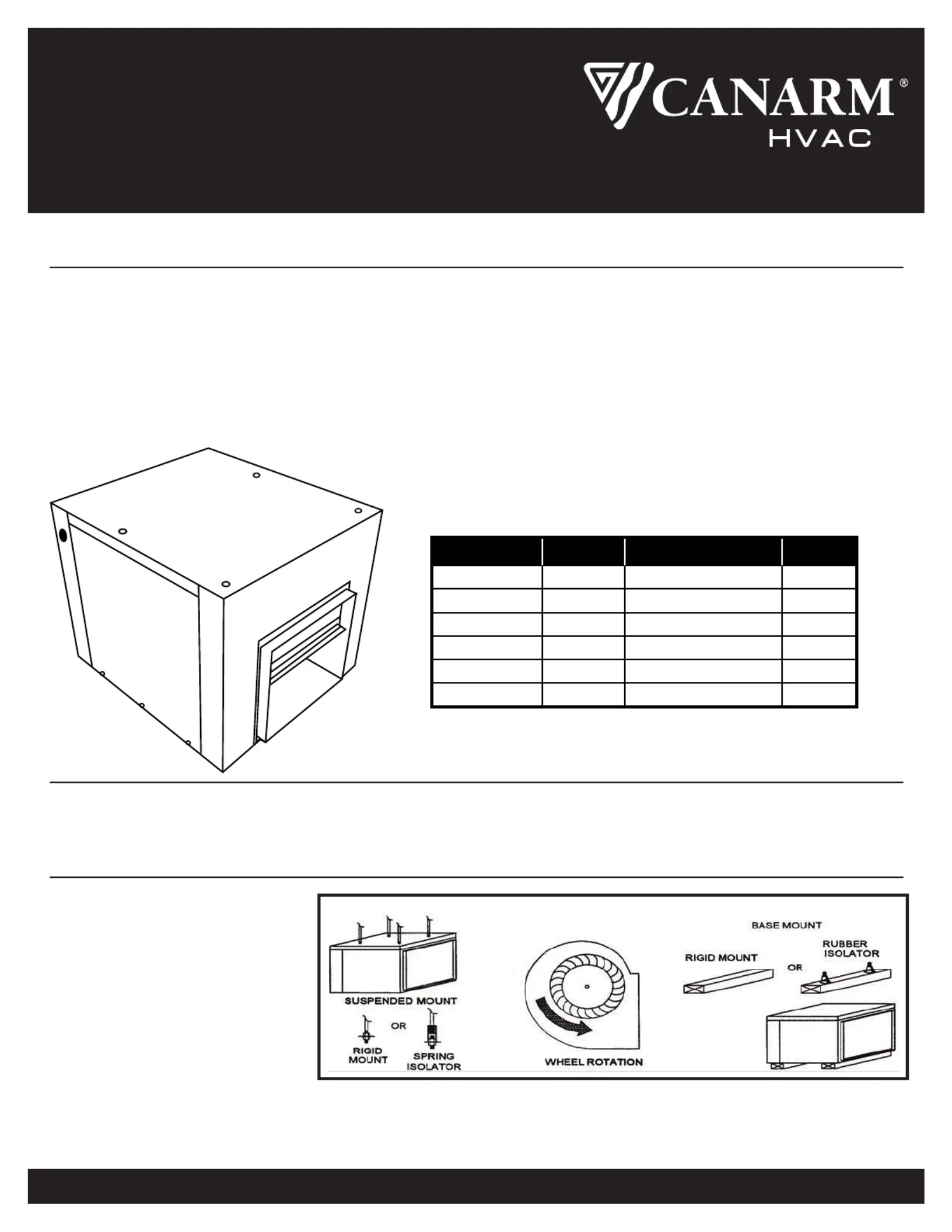
| Model: | IDB1210150 |
Har du brug for hjælp?
Hvis du har brug for hjælp til Canarm IDB1210150 stil et spørgsmål nedenfor, og andre brugere vil svare dig
Ventilator Canarm Manualer


Ventilator Manualer
- Termozeta
- Maxim
- Melchioni
- BEEM
- Qlima
- Omega Altise
- DCG
- Stylies
- TriStar
- Kogan
- Listo
- Exquisit
- James
- NewAir
- OneConcept
Nyeste Ventilator Manualer


