Candy FRCTCA451VAS Manual

Candy Køleskab FRCTCA451VAS

Læs gratis den danske manual til Candy FRCTCA451VAS (76 sider) i kategorien Køleskab. Denne vejledning er vurderet som hjælpsom af 35 personer og har en gennemsnitlig bedømmelse på 4.3 stjerner ud af 18 anmeldelser. Har du et spørgsmål om Candy FRCTCA451VAS, eller vil du spørge andre brugere om produktet?

Side 1/76
I
F
D
GB
NL
E
P
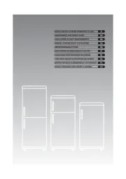
COMBINATI
COMBINES
HL-GEFRIER-KOMBINATIONEN
COMBIS
COMBINATIEKASTEN
COMBINADOS
COMBINADOS
7
Italiano pag. 3 - 12
Français page 13 - 22
Deutsch Seite 23 - 33
English page 34 - 42
Nederlands pag. 43 - 51
Español pag. 52 - 61
Português pág. 62 - 73
zando impropriamente oggetti taglienti o appuntiti) sia esternamente (operazioni impro-
prie durante la pulizia del circuito condensatore).
Al termine della vita funzionale dell'apparecchio, lo stesso dovrà essere messo in sicurez-
za prima dell'invio alla discarica. Per queste operazioni rivolgersi al Vs. negoziante o
all'Ente Locale preposto.
USO DEL COMPARTO FRIGORIFERO
Per conservare al meglio aroma, sostanza e freschezza di tutti i cibi da riporre, racco-
mandiamo di avvolgerli preventivamente in fogli di alluminio o di plastica o negli appositi
contenitori con coperchio. Ciò evita inoltre che gli odori si sovrappongano.
Consigliamo di riporre i cibi come indicato di seguito:
Carni in genere, salumi, pesce: sulla griglia sopra il cassetto frutta e verdura.
Cibi cotti, torte, ecc.: sulle griglie superiori.
Uova e latticini: nella controporta dell'apparecchio.
Frutta e verdura: nell'apposito cassetto all'interno di sacchetti in polietilene, preferibilmen-
te preforati per una migliore condizione di conservazione.
Prodotti in scatola: una volta aperta la scatola, togliere il rimanente e conservare in un
altro contenitore che non sia di metallo.
Importante: Assicurare fra le varie confezioni, la libera circolazione dell'aria.
Riporre i cibi cotti solo raffreddati ed i liquidi in contenitori coperti.
SPIEGAZIONE SIMBOLI
Frigoriferi
Lo scomparto a bassa temperatura è adatto alla conservazione dei cibi surgelati per
breve termine (circa una settimana).
Frigoriferi
Lo scomparto a bassa temperatura è adatto alla conservazione dei cibi surgelati per
medio termine (un mese circa).
Frigoriferi
Lo scomparto a bassa temperatura è adatto alla conservazione dei cibi surgelati per
lungo termine (circa tre mesi) e alla conservazione di gelati e prodotti similari.
Frigoriferi - Frigo/congelatori
Il simbolo indica la possibilità di conservare a bassa temperatura i surgelati per lungo ter-
mine nonché di congelare i cibi freschi, secondo le indicazioni riportate nella tabella di
congelamento.
REGOLAZIONE TEMPERATURE
La temperatura ambiente, il carico e la frequenza d'apertura della porta dell'elettrodome-
stico influiscono sulla temperatura interna. Quando si modifica la regolazione, la macchi-
na frigorifera può non mettersi subito in moto perchè è in pausa. La regolazione delle
temperature è ottenuta agendo sulla manopola del termostato che si trova all'interno o
all'esterno del frigorifero. Sulla posizione "0" il frigorifero non funziona. "0" significa
fermo.
Si consiglia di tenere la manopola del termostato su una posizione media.
Ruotando la manopola in senso orario si ottengono temperature sempre più basse.
5
In presenza di temperature ambiente molto calde l'apparecchio può funzionare in
continuo, con conseguente anomala formazione di brina, in questi casi occorre
ruotare la manopola del termostato verso i numeri più bassi.
QUADRO COMANDI PER APPARECCHI DA INCASSO DUE COMPRESSORI E
MONO COMPRESSORI (fig. 2)
La versione due compressori si distingue per avere la regolazione del vano frigorifero all’interno
della cella frigorifero, mentre lo scomparto congelatore è regolato dal quadro comandi (fig. 2).
Il termostato “D” comanda il congelatore.
Sulla posizione “0” il congelatore non funziona.
Ruotando la manopola in senso orario l’apparecchio si avvia e si accende la spia verde “A”.
Posizionando la manopola termostato su “S” (congelamento rapido) si accende la spia
gialla “C” ed il compressore funziona in continuo per 50 ore. Allo scadere delle 50 ore la
spia gialla “C” lampeggia per indicare che la fase di congelamento è terminata e la mano-
pola del termostato deve essere riportata sulla posizione di normale utilizzo.
La spia rossa “B” se accesa indica che la temperatura nella cella congelatore non è suffi-
cientemente bassa e ciò può dipendere da:
- apparecchio appena messo in funzione
- porta rimasta aperta o non chiusa bene
- introduzione di prodotti da congelare.
La spia rossa si spegne quando la temperatura interna prevista viene raggiunta.
La versione mono compressore ha un’unica regolazione (fig. 2).
Il termostato “D” comanda il frigorifero e congelatore.
Sulla posizione “0” il frigorifero ed il congelatore non funzionano.
Ruotando la manopola in senso orario l’apparecchio si avvia e si accende la spia verde “A”.
Posizionando la manopola termostato su “S” (congelamento rapido) si accende la spia
gialla “C” ed il compressore funziona in continuo per 6 ore. Allo scadere delle 6 ore la
spia gialla “C” lampeggia per indicare che la manopola del termostato deve essere ripor-
tata sulla posizione di normale utilizzo.
La spia rossa “B” se accesa indica che la temperatura nella cella congelatore non è suffi-
cientemente bassa e ciò può dipendere da:
- apparecchio appena messo in funzione
- porta rimasta aperta o non chiusa bene
- introduzione di prodotti da congelare.
La spia rossa si spegne quando la temperatura interna prevista viene raggiunta.
QUADRO COMANDI (fig.4B – fig.13) COMBI BICOMPRESSORE
Il termostato “A” comanda il vano congelatore, ruotando la manopola in senso orario si
avvia il vano freezer e si accendono le spia verde “B” e la spia rossa “C”. La spia rossa
“C” si spegnerà solo quando la temperatura interna prevista viene raggiunta.
La spia gialla “E” si accende, nei modelli con cruscotto di fig.4b, quando viene premuto il
tasto di congelazione rapida “F” mentre per i modelli con il cruscotto di fig.13, quando si
ruota la manopola “A” nella posizione “SUPER” (S).
Il termostato “H” comanda il vano frigorifero, sulla posizione “0” il frigorifero non funziona.
Ruotando la manopola “H” in senso orario il vano frigorifero si avvia e si accende la spia
verde “G”.
QUADRO COMANDI (fig.4) COMBI MONOCOMPRESSORE CON ELETTROVALVOLA
Il termostato “A” comanda il vano congelatore, in posizione “0” viene disinserito il funzio-
namento di entrambi i vani freezer e frigorifero; in posizione diversa da “0” la manopola
6
“H” permette la regolazione del vano frigorifero.
Ruotando la manopola “A in senso orario si avvia il vano freezer, si accende la spia
verde “B” e lampeggia la spia rossa “C”. Detta operazione è da eseguire solo all’avvia-
mento dell’apparecchio.
Le quattro spie verdi “D” indicano la temperatura all’interno del vano congelatore. La spia
segnala una temperatura indicativa del valore medio presente in cella.
La spia gialla “E” si accende quando viene tenuto premuto il tasto di congelamento “F”
per un tempo di 4 secondi e mette in funzionamento continuo il compressore.
Il termostato “H” comanda il vano frigorifero. Sulla posizione “0” lo scomparto frigorifero
non funziona.
Ruotando la manopola “H” in senso orario il vano frigorifero si avvia e si accende la spia
verde “G” (solo se la manopola termostato “A” è in una posizione diversa da “0”.
Il frigorifero funziona solo se è accesa la spia verde “B”.
Segnalazione di avvenuta anomalia: quando la luce rossa C lampeggia ed una della quattro
spie verdi D è accesa, significa che per mancata alimentazione di energia elettrica o altre
anomalie gli alimenti nello scomparto congelatore sono stati per un certo tempo ad una tempe-
ratura superiore a 0; per disinserire il lampeggio della spia rossa C tenere premuto il tasto “F.
Per un corretto uso del congelatore vi suggeriamo di regolare la relativa manopola termo-
stato in modo che si accenda sul termometro la spia verde “X”. Si otterrà così una con-
servazione ottimale.
QUADRO COMANDI (fig.13) COMBI MONOCOMPRESSORE CON ELETTROVALVOLA
Il termostato “A” comanda il vano congelatore, in posizione “0” viene disinserito il funzio-
namento di entrambi i vani freezer e frigorifero; in posizione diversa da “0” la manopola
“H” permette la regolazione del vano frigorifero.
Ruotando la manopola “A” in senso orario si avvia il vano freezer, si accendono la spia
verde “B” e la spia rossa “C”, quest’ultima si spegnerà solo quando la temperatura interna
prevista viene raggiunta.
La spia gialla “E” si accende ruotando la manopola “A” in posizione “SUPER” mettendo in
funzionamento continuo il compressore freezer.
Il termostato “H” comanda il vano frigorifero. Sulla posizione “0” lo scomparto frigorifero
non funziona.
Ruotando la manopola “H” in senso orario il vano frigorifero si avvia e si accende la spia
verde “G” (solo se la manopola termostato “A” è in una posizione diversa da “0”.
Il frigorifero funziona solo se è accesa la spia verde “B”.
QUADRO COMANDI (fig.4 – fig.4b – fig.13)
La spia rossa “C” se accesa indica che la temperatura nella cella congelatore non è suffi-
cientemente bassa e ciò può dipendere da:
- apparecchio appena messo in funzione
- porta rimasta aperta
- introduzione di prodotto da congelare.
Il congelatore deve comunque garantire sempre temperature uguali o inferiori a -18° C.
ATTENZIONE: non esiste alcuna correlazione tra i numeri indicati sulla manopola termo-
stato (A) e le temperature riportate sulle 4 spie verdi (D).
QUADRO COMANDI (fig. 12)
Il termostato "A" comanda frigorifero e congelatore.
Sulla posizione "0" il frigorifero e il congelatore non funzionano.
Ruotando la manopola in senso orario l'apparecchio si avvia e si accende la spia verde "B".
7
ne del carico e della temperatura ambiente. Alla fine della congelazione, riportare la
manopola termostato nella posizione abituale.
Versione incasso mono compressore con quadro comandi (fig. 2)
In aggiunta a quanto riportato per i combinati senza quadro comandi:
per una migliore congelazione, qualora la temperatura ambiente sia superiore a 3C, si
consiglia di ruotare il termostato sulla posizione “S” di congelazione rapida per circa 6 ore
prima dell’introduzione dei cibi freschi.
Allo scadere delle 6 ore (quando la spia “C” lampeggia) riportare il termostato sulla posi-
zione di normale funzionamento diversa da “S”.
PER TUTTI GLI APPARECCHI: la quantità massima da congelare, secondo le modalità
previste dalle norme europee, è indicata in targa matricola.
SBRINAMENTO
La cella frigorifera ha lo sbrinamento automatico che avviene durante i tempi di pausa del
compressore. Nel corso della pausa le gocce d'acqua che si formano per lo scioglimento
della brina defluiscono nell'apposita bacinella posta sopra il compressore che con il calo-
re generato ne provoca l'evaporazione.
È opportuno non disporre i cibi e il contenitore contro la parte di fondo.
Per lo sbrinamento comparto congelatore agire come segue:
a) 24 ore prima dello sbrinamento ruotare la manopola del termostato verso i numeri alti o
inserire l'interruttore di congelamento rapido, per portare i cibi ad una temperatura p bassa.
b) Avvolgere i cibi congelati in fogli di carta per alimenti sistemandoli in frigorifero o in un
ambiente fresco.
c) Mettere il termostato su "0" oppure dove è previsto spegnere l'interruttore verde.
d) Lasciare la porta aperta.
e) A sbrinamento effettuato asciugare l'interno e risistemare i cibi precedentemente tolti.
f) Mettere il frigorifero nelle condizioni iniziali e lasciar funzionare l'apparecchio con il ter-
mostato sui numeri alti.
Fig. 9) Importante: il congelatore è dotato di un sistema di evacuazione d'acqua di sbrina-
mento costituito da uno sgocciolatoio pieghevole in gomma posizionato sul bordo inferio-
re della cella.
Fig. 10) Importante: su alcuni combinati l'acqua di sbrinamento viene fatta defluire dall'in-
terno del congelatore, tramite un condotto (chiuso con un tappino) collegato ad un goc-
ciolatoio ricavato sullo zoccolo.
In alcuni modelli il gocciolatoio deve essere estratto dallo zoccolo, e riposizionato al ter-
mine dell'operazione di sbrinamento (fig. 10b).
N.B.: ricordarsi di togliere il tappino che chiude il condotto per fare defluire l'acqua di sbri-
namento e rimetterlo ad operazione avvenuta.
Modelli con dispensatori di liquidi
Alcuni modelli sono dotati di dispensatori di liquidi, unitamente ad un contenitore bottiglia
completo di griglia raccogli-gocce applicati alla controporta.
Istruzioni per l'applicazione e l'uso:
1) Fig. 8A - Tirare in avanti la griglietta "K" fino a sentire il fermo e sfilare il contenitore
"H" dalla controporta sollevandolo verso l'alto.
2) Fig. 8B - Sfilare il dispensatore "Z" dal contenitore "H", avvitarlo sulla bottiglia e reinse-
rirlo nel contenitore.
9
3) Fig. 8A - Montare il contenitore "H" sulla controporta inserendolo negli appositi agganci
con un movimento verticale dall'alto verso il basso e bloccarlo alla controporta spingendo
a fondo la griglietta "K".
4) Fig. 8A - Il dispensatore è pronto all'uso, per il prelievo della bevanda appoggiare il
bordo del bicchiere sulle tre razze e spingere verso l'alto.
5) Fig. 8A - Pulizia del vano raccogli-gocce: tirare in avanti la griglietta "K" fino a sfilarla,
pulire la sede del deposito liquido e reinserire la griglietta opportunamente pulita.
N.B.: Dopo un frequente uso del dispensatore con bevande zuccherate, pulirlo con acqua.
PULIZIA
Ad evitare formazioni di cattivi odori è consigliabile una pulizia periodica all'interno del fri-
gorifero e delle guarnizioni magnetiche porte almeno due o tre volte l'anno.
a) Prima di effettuare qualsiasi operazione di pulizia o di manutenzione, disinserire l'ap-
parecchio dalla rete di alimentazione elettrica staccando la spina (non basta portare la
manopola del termostato sulla posizione "0").
b) Svuotare il congelatore dai cibi e dai cubetti di ghiaccio. (vedi "Sbrinamento").
c) Attendere che la brina sull'evaporatore sia sciolta.
d) Pulire l'interno dell'apparecchio usando acqua tiepida con aggiunta di uno o due cuc-
chiai di bicarbonato di sodio, risciacquare ed asciugare. ATTENZIONE non usare detersi-
vi, abrasivi o solventi.
e) Prima di riporre i cibi nel congelatore farlo ripartire.
f) Pulire il foro scarico acqua saltuariamente utilizzando l'apposito accessorio (fig. 5),
lasciandolo anche inserito nel foro di scarico.
g) L'eventuale presenza di un leggero velo di ghiaccio sulla parete di fondo della cella fri-
gorifero è da considerarsi normale in quanto si dissolve ad ogni pausa del compressore.
Quando l'apparecchio deve rimanere per lunghi periodi inattivo, dopo un'accurata pulizia,
lasciare la spina di alimentazione staccata e la porta socchiusa.
ASSISTENZA TECNICA
Per l'eventuale riparazione rivolgersi solamente ad un centro di assistenza tecnica autorizzato
dal costruttore e richiedere l'utilizzo di ricambi originali. Il mancato rispetto di quanto sopra p
compromettere la sicurezza dell'apparecchio. Se il vostro frigorifero non funziona o se il suo
funzionamento è anormale, controllate questi punti prima di richiedere l'Assistenza Tecnica.
1) Arriva la corrente alla presa a cui è allacciato il frigorifero? Provatelo con una lampada.
2) La spina di allacciamento è forse staccata dalla presa di corrente? Inseritela.
3) Il termostato è forse sulla posizione "0" (fermo)? Giratelo sulla posizione 3.
4) Avete forse lasciato formarsi uno strato di brina troppo spesso sull'evaporatore (più di
4-5 mm)? Scongelatelo (vedi "Sbrinamento").
5) Sono forse stati mal disposti i cibi all'interno del congelatore impedendo la libera circo-
lazione dell'aria?
6) È libera la circolazione dell'aria intorno al condensatore posto dietro l'apparecchio?
Allontanatelo dal muro.
Se il problema dovesse persistere, componendo il
“Numero Utile” indicato a lato sarete messi in contat-
to direttamente con il Centro Assistenza Autorizzato
a Voi più vicino.
È importante che comunichiate al Centro Assistenza Tecnica il modello che troverete scrit-
to sulla targhetta posta all'interno del frigorifero (o sul foglio di garanzia).
10
SERVIZIO ASSISTENZA TECNICA
199.123.123
Fornendo tali informazioni otterrete un intervento più tempestivo ed adeguato.
Importante: il riscaldamento perimetrale della cella congelatore è indice di corretto fun-
zionamento.
INVERSIONE DEL SENSO DI APERTURA DELLE PORTE (dove è previsto) vedere
fig. 3
1) Si consiglia di sdraiare o inclinare di circa 45° il frigorifero, essendo necessario operare
sulla parte inferiore dell'apparecchio per poter togliere la cerniera inferiore.
2) Smontare lo zoccolo se presente.
3) Togliere la cerniera inferiore (e le relative rondelle), agendo sulle viti A indicate in figura.
4) Togliere la porta inferiore.
5) Togliere la cerniera centrale e le relative rondelle agendo sulle viti B come indicato in
fig. 3. Sui modelli con porta superiore alta (fig.7d), prima di togliere le viti che fissano la
cerniera centrale, aprire la porta, togliere il tappo M e la chiusura testata alta L.
6) Togliere la porta superiore. Dove è impiegato il fermo porta (fig.7e) togliere quello di
destra N agendo sulla vite. Dalla busta accessori prelevare il fermo porta di sinistra e fis-
sarlo con la vite tolta in precedenza.
7) Asportare dal cruscotto la membrana di plastica che ricopre la cerniera superiore sinistra.
8) Svitare il perno C della cerniera superiore destra e rimontarlo a sinistra. Sui modelli
con porta superiore alta (fig.7c), togliere i tappi F-G, il perno D e la cerniera superiore
destra agendo sulle viti. Dalla busta accessori prelevare la cerniera superiore sinistra H e
fissarla al mobile con le viti tolte in precedenza; rimontare il perno D con la relativa ron-
della e i tappi F-G. Rompere la membrana del tappo G per permettere la fuoriuscita della
cerniera.
9) Rimontare le porte operando in senso inverso (6-5-4-3-2); ricordandosi di rimontare
anche le rondelle distanziatrici interposte tra porta e cerniera.
10) Spostare le maniglie verticali, qualora esistano, dal lato sinistro al lato destro agendo
sulle viti corrispondenti; nel caso di maniglie con marchio “M” (fig. 7b), spostare le mani-
glie da sinistra a destra incrociandole, togliere il marchio adesivo dalla maniglia di sini-
stra, prelevare dal kit accessori il nuovo marchio, togliere la protezione adesiva e posizio-
narlo sulla maniglia di destra.
11) Riportare l'apparecchio in posizione verticale.
N.B. Per ottenere un corretto allineamento delle porte è necessario agire sulla cerniera
centrale.
INVERSIONE DEL SENSO DI APERTURA DELLE PORTE (dove è previsto) vedere
fig. 7
Per modelli con cerniera inferiore montata sia a destra che a sinistra.
1) Si consiglia di inclinare il frigorifero di circa 45°.
2) Togliere le viti (A) che fissano la cerniera centrale. Sui modelli con porta superiore alta
(fig.7d), prima di togliere le viti che fissano la cerniera centrale, aprire la porta, togliere il
tappo M e la chiusura testata alta L.
3) Togliere la porta superiore. Dove è impiegato il fermo porta (fig.7e) togliere quello di
destra N agendo sulla vite. Dalla busta accessori prelevare il fermo porta di sinistra e fis-
sarlo con la vite tolta in precedenza.
4) Togliere la cerniera centrale.
5) Togliere la porta inferiore.
6) Asportare dal cruscotto e dallo zoccolo la membrana di plastica che ricopre la cerniera
superiore sinistra e la cerniera inferiore sinistra.
7) Svitare il perno (B) della cerniera inferiore destra e rimontarlo a sinistra.
11
aboutisse dans la cuvette d'évaporation placée à l'arrière du réfrigérateur, au-dessus du
compresseur.
Le réfrigérateur peut-être aussi installé sous les éléments de cuisine; dans ce cas la libre
circulation de l'air doit être garantie, laissant un espace libre d'environ 5 centimètres entre
le meuble et l'appareil ou dans la partie postérieure du meuble.
Une mauvaise installation peut causer des dommages aux personnes, aux animaux et
aux choses et le constructeur ne peut en être retenu responsable.
CONSEILS POUR LE CONTRÔLE DE LA TEMPÉRATURE ET POUR LE RESPECT
DES RÈGLES D'HYGIÈNE ALIMENTAIRE
Une bonne utilisation du réfrigérateur et le respect des règles hygiéniques alimentaires
contribuent de façon significative à une meilleure conservation des aliments.
Contrôle de la température
Placer les aliments les plus délicats dans la zone la plus froide de l'appareil: en général,
la basse au-dessus des tiroirs à fruits et à légumes.
Les aliments cuits doivent être mis dans des récipients hermétiques, laisser refroidir puis
placer dans la zone centrale du réfrigérateur.
Les fruits et les légumes doivent être placés dans les récipients prévus à cet effet dans la
partie basse du réfrigérateur.
Respect des règles d'hygiène alimentaire
Eliminer les enveloppes d'emballage avant de mettre les aliments à l'intérieur du réfrigé-
rateur.
Emballer les aliments frais: de cette façon, ils se conservent plus longtemps et on évite
qu'ils se contaminent mutuellement.
Disposer les aliments frais de façon que l'air puisse circuler librement à l'inrieur du
réfrigérateur.
Nettoyer fréquemment l'intérieur du frigérateur en utilisant des détergents délicats mais
qui ont un pouvoir bactéricide certain.
INFORMATIONS POUR L'ENVIRONNEMENT
Emballage, traitement des déchets
Après avoir déballé l'appareil, ne pas jeter l'emballage à la poubelle mais trier les diffé-
rents matériaux (comme le polystyrène, le carton, etc. ...) selon les prescriptions locales
pour l'élimination des ordures et selon les normes en vigueur.
Attention
Cet appareil est produit sans utiliser de CFC; le circuit frigérant contient un fluide HFC
R 134a ou, alternativement, du gaz isobutane R 600 a. Pour plus de détails, voir la pla-
que signalétique.
Pour les opérations de nettoyage, n'utiliser aucun outil ou thode autre que ce qui est
décrit dans le chapitre s'y rapportant pour éviter d'endommager l'appareil.
Pour les appareils à l'isobutane (R 600 a)
L'isobutane est un gaz naturel qui n'a aucun effet sur l'environnement mais qui est inflam-
mable. Il est donc indispensable de s'assurer que:
- l'installation de l'appareil se fait dans locaux ayant un volume libre de plus de 3 mètres
cube;
14
- les ouvertures de ventilation de l'appareil sont maintenues libres et propres;
- le circuit réfrigérant de l'appareil n'est pas endommagé, que ce soit intérieurement (en
utilisant des objects coupants ou pointus de façon incorrecte) ou extérieurement (opéra-
tions incorrectes en cours de nettoyage du circuit condensateur).
Au terme de la durée de vie de l'appareil, celui-ci devra être mis en condition de sécurité
avant de l'envoyer à la charge. Pour cela, s'adresser à votre revendeur ou à l'admini-
stration locale chargée de cela.
UTILISATION DU COMPARTIMENT RÉFRIGÉRATEUR
Pour conserver l'arôme au mieux, substance et fraîcheur de tous les aliments à disposer,
nous vous recommandons de les enrouler préalablement dans des feuilles d'aluminium
ou de plastique ou de les placer dans les bacs appropriés avec couvercle.
Il est ainsi évité toute superposition d'arômes.
Nous conseillons de disposer les aliments comme suit:
Viandes en général, poissons, charcuterie: sur la grille au dessus du bac fruits et légumes.
Aliments cuits, gâteaux, etc...: sur les grilles supérieures.
Oeufs et boites de lait: dans la contreporte de l'appareil.
Fruits et légumes: dans le bac prévu à cet effet, s'ils sont emballés dans un sachet "pla-
stique"; il est préférable de le percer pour une meilleure conservation.
Produits et conserve: une fois la boite ouverte, retirer la nourriture restante et la conser-
ver dans un autre récipient qui ne soit pas en métal.
Important: S'assurer d'une circulation de l'air entre les différents conditionnements.
Remettre les aliments cuits uniquement refroidis ainsi que les liquides dans des bacs
avec couvercle.
EXPLICATION DES SYMBOLES
Réfrigérateur
Le compartiment à basse température est idéal pour la conservation des aliments sur-
gelés pendant une période limitée (une semaine environ).
Réfrigérateur
Le compartiment à basse température est idéal pour la conservation des aliments sur-
gelés pendant une période moyenne (un mois environ).
Réfrigérateur
Le compartiment à basse température est idéal pour la conservation des aliments sur-
gelés pendant une période prolongée (trois mois environ), pour la conservation des crè-
mes glacées et des produits similaires.
Réfrigérateur - Réfrigérateur/Congélateur
Le symbole indique la possibilité de congeler les produits frais et de conserver à basse
température les produits surgelés pendant une période prolongée, selon les indications
du tableau de congelation.
REGLAGE DE LA TEMPERATURE
La température ambiante, la charge et la fréquence d'ouverture de la porte de l'appareil
électro-ménager, influencent la température interne. Quand on modifie le réglage, l'appa-
reil peut ne pas démarrer immédiatement car il est en pause. Le réglage de la températu-
15
re se fait en agissant sur la manette du thermostat qui se trouve à l'interieur ou à l'exté-
rieur du réfrigérateur. Sur la position "0" le réfrigérateur ne fonctionne pas, "0" signifie arrêt.
Il est préférable de mettre le bouton du thermostat en position intermédiaire.
En tournant le bouton du thermostat dans le sens des aiguilles d'une montre, la tempéra-
ture dans le réfrigérateur descend.
Si la température de votre pièce est élevée, le réfrigérateur fonctionne continuelle-
ment, ceci pouvant occasionner la formation de givre. Dans ce cas, mettre le bou-
ton du thermostat sur une position moins élevée.
VERSION MONO COMPRESSEUR ET DOUBLE COMPRESSEUR ENCASTRABLES
AVEC BANDEAU DE COMMANDE
Dans la version “double compresseurs” la temrature de la partie “réfrigérateur est
réglable à l’intérieur du compartiment réfrigérateur tandis que celle de la partie “congéla-
teur” est réglable sur le bandeau de commande (fig. 2).
Le thermostat “D” contrôle le compartiment “congélateur”.
Sur la position “0”, le congélateur ne fonctionne pas.
En tournant le bouton dans le sens horaire, le congélateur se met en route et le moin
lumineux vert “A” s’allume.
En positionnant le bouton sur “S (congélation rapide), le témoin lumineux jaune C”
s’allume et le compresseur fonctionne en continu pendant 50 heures. Au bout de 50 heu-
res, le témoin jaune clignote indiquant que la congélation rapide est terminée et que le
thermostat doit être replacé en position normale.
Le témoin lumineux d’alarme rouge “B” s’allume lorsque la température dans le congéla-
teur n’est pas correcte. Cela signifie que:
- l’appareil vient juste d’être mis en route
- la porte est restée ouverte ou mal fermée
- insertion d’aliments frais à congeler trop importante.
Le moin lumineux d’alarme rouge s’éteindra lorsque la température du congélateur cor-
recte sera atteinte.
La version “simple compresseur” ne possède qu’une seule sélection sur le bandeau de
commande (fig. 2).
Le thermostat ”D” contrôle les compartiments “congélateur” et “réfrigérateur”.
Sur la position “0”, l’appareil ne fonctionne pas.
En tournant le bouton dans le sens horaire, l’appareil se met en route et le moin lumi-
neux vert “A” s’allume.
En positionnant le bouton sur “S (congélation rapide), le témoin lumineux jaune C”
s’allume et le compresseur fonctionne en continu pendant 6 heures. Au bout de 6 heures,
le témoin jaune clignote indiquant que la congélation rapide est terminée et que le ther-
mostat doit être replacé en position normale.
Le témoin lumineux d’alarme rouge “B” s’allume lorsque la température dans le congéla-
teur n’est pas correcte. Cela signifie que:
- l’appareil vient juste d’être mis en route
- la porte est restée ouvert ou mal fermée
- insertion d’aliments frais à congeler trop importante.
Le moin lumineux d’alarme rouge s’éteindra lorsque la température du congélateur cor-
recte sera atteinte.
BANDEAU DE CONTROLE (fig. 4b & fig. 13) POUR RÉFRIGÉRATEUR BI-COMPRESSEUR
Le thermostat "A" contrôle la congélation. Tournez la manette dans le sens des aiguilles
d’une montre , le congélateur se met en marche et les voyants "B" vert et "C" rouge
16
Motifs du dysfonctionnement :
- l’appareil vient juste d’être mis en marche
- porte laissée ouverte ou entrebâillée
- aliments frais à congeler introduits depuis peu dans le congélateur.
Le congélateur doit de toute façon toujours garantir des températures égales ou inférieu-
res à -18°C.
ATTENTION: il n'y a pas de rapport entre les numéros indiqués sur la poignée thermostat
(A) et les températures indiquées sur les 4 voyants lumineux verts (D).
TABLEAU DE BORD (fig. 12)
Le thermostat "A" contrôle le réfrigérateur et le congélateur.
Sur la position "0", réfrigérateur et congélateur sont hors fonctionnement.
En tournant la manette du thermostat dans le sens des aiguilles d'une montre, l'appareil
fonctionne et le voyant vert "B" s'allume.
CONSERVATION
Quelques modèles possédent un compartiment placé en haut du congélateur, sur la par-
tie haute de l'évaporateur, le compartiment est un "2 étoiles" comme indiqsur la pla-
que signalétique.
Les conditions maximales de conservation s'obtiennent en retirant tous les paniers,
excepté celui du bas.
Le symbole indique la possibilité de conserver le "surgelé" à basse température
pendant une longue période, ainsi que de congeler des poduits frais.
Les temps de conservation dépendent strictement du maintien de la température; par
conséquent des variations éventuelles de température influent directement sur la durée
de la conservation.
En cas de panne d'électricité, n'ouvrez absolument pas la porte ou le couvercle. Les
denrées conservées ne subissent aucun dommage si la panne dure de 10 à 12 heures.
En cas d'interruption plus longue, enveloppez les produits dans du papier spécial pour
aliments et placez-les, autant que possible, dans un réfrigérateur ou, à la limite, dans un
endroit frais. En tout cas il est conseillé de consommer ces denrées dans un délai de 24
heures ou de les faire cuire et de les congeler ensuite.
CONGELATION
La performance maximale de congélation est obtenue en retirant les paniers excep
celui du bas.
Réfrigérateur-congélateur avec bandeau de contrôle (fig. 2, fig. 4, fig. 4b et fig13)
Avant de congeler des aliments frais, nous vous conseillons de transférer les aliments
déjà congelés du compartiment supérieur au compartiment inférieur, de manière à laisser
la place aux produits frais.
24 heures avant de congeler des aliments, suivre les instructions suivantes :
Bandeau de contrôle (fig.4 – fig. 4b)
Pour activer la fonction congélation rapide, enfoncez le bouton "F" pendant 4 secondes
minimum, le voyant jaune s’allume et indique que le processus de congélation rapide est
enclenché. Cette fonction sarrêtera automatiquement après 50 heures et l’appareil
reprendra les fonctions initialement sélectionnées.(le voyant jaune s’éteint). Si vous
souhaitez arrêter le processus de super congélation avant ce laps de temps, enfoncez le
bouton "F" pendant plus de 4 secondes.
Bandeau de contrôle (fig.13)
Pour activer la fonction congélation rapide,, tournez la manette "A" dans le sens des
aiguilles d’une montre sur la position "Super", le voyant jaune "E" s’allume pour indiquer
que le processus de congélation rapide est enclenché. Cette fonction s’arrêtera automati-
18
quement 50 heures après et l’appareil reprendra les fonctions initialement sélectionnées
(le voyant jaune s’éteint).
Pour ramener l’appareil aux fonction initialement sélectionnées, tournez la manette "A"
sur la position initiale, autre que "Super".
Bandeau de contle (fig. 2) pourfrigérateur-congélateur intégrable bi-compresseur
Pour activer la fonction congélation rapide,, tournez la manette "D" dans le sens des
aiguilles d’une montre sur la position "Super", le voyant jaune "C" s’allume.Au bout de 50
heures, lorsque le programme de congélation rapide est terminé, le voyant jaune "C" cli-
gnotera pour indiquer que la manette de thermostat doit être positionnée sur la fonction
de marche normale.
Combinés Réfrigérateur/Congélateur, avec ou sans tableau de bord (fig. 12)
24 heures avant le début de la congélation, faire de la place pour les produits à congeler.
Au début de la congélation, pour ne pas faire refroidir excessivement le compartiment
réfrigérateur, il peut être cessaire de ramener d'environ 1/2 numéro la poignée du ther-
mostat, en fonction du chargement et de la température ambiante. A la fin de la congéla-
tion, remettre la poignée du thermostat sur la position habituelle.
Mono compresseur intégrable avec bandeau de commande (fig. 2)
Additif spécifique aux Réfrigérateurs Congélateurs sans bandeau de commande:
pour augmenter l’efficacité de congélation lorsque la température ambiante est supérieu-
re à 30° C, actionner la congélation rapide en positionnant le bouton sur la position «S»
au moins 6 heures avant d’introduire des aliments frais à congeler.
Après 6 heures (lorsque le voyant "C" clignote) positionnez la manette de thermostat sur
une position de marche autre que "Super".
POUR TOUS LES APPAREILS: la quantité maximum à congeler est, selon les modalités
prévues par les normes européennes, indiquée sur la plaque signalétique.
DEGIVRAGE
Le compartiment frigorifique est équipé d'un système de givrage automatique qui s'ef-
fectue pendant les temps de pause du compresseur. Au cours de ce cycle, les gouttes
d'eau qui se forment par suite du givre qui fond, se posent dans le bac placé au-des-
sus du compresseur qui, par la chaleur, en provoque l'évaporation.
Ne pas placer de denrées ou de récipients en contact avec la paroi arrière.
Pour les compartiments de congélation des "double porte" agir comme suit:
a) 24 heures avant de givrer, tourner la manette du thermostat vers les positions les
plus froides ou brancher l'interrupteur de congélation rapide afin de donner aux aliments
la température la plus basse.
b) Envelopper les aliments surgelés ou congelés dans du papier alimentaire et les placer
soit dans le réfrigérateur soit dans un endroit frais, en veillant à ce qu'ils ne décongèlent pas.
c) Placer le thermostat sur la position "0" ou, s'il est prévu, éteindre l'interrupteur vert.
d) Laisser la porte ouverte.
e) Une fois le givrage effectué nettoyer et sécher l'intérieur de l'appareil et remettre en
place les aliments.
f) Remettre l'appareil dans les conditions initiales et le laisser fonctionner avec le thermos-
tat positionné sur la position de plus grand froid.
Fig. 9) Important: Le congélateur est pourvu d'un système d'évacuation de l'eau de dégivra-
ge se composant d'un égouttoir en caoutchouc, placé sur le bord inférieur du compartiment.
Fig. 10) Important: l'eau de dégivrage est évacuée (seulement sur quelques modèles) de
l'intérieur du congélateur vers l'extérieur à travers un conduit (fermé par un bouchon relié
à un ramasse - goutte aménagé sur le socle).
Sur quelques modèles, l'égouttoir doit être retiré de son socle, et remis en place dès la fin
de l'opération de dégivrage (Fig. 10b).
19
N.B.: Se rappeler d'enlever le bouchon qui ferme le conduit pour faire couler l'eau de
dégivrage puis le remettre une fois l'opération terminée.
Modèles avec distributeur de liquide:
Certains sont dotés d'un distributeur de liquide composé d'un distributeur et d'un égout-
toir; l'ensemble s'applique à la contre-porte.
Instructions pour l'application et l'utilisation
1) Fig. 8A - Tirer vers l'avant la petite grille "K" jusqu'à sentir l'arrêt et disposer le conte-
neur "H" de la contre-porte en soulevant vers le haut.
2) Fig. 8B - Positionner le distributeur "Z" du conteneur "H" en le vissant sur la bouteille et
l'introduire dans le conteneur.
3) Fig. 8A - Monter le conteneur "H" dans la contre-porte en l'insérant dans les crochets
par un mouvement vertical du haut vers le bas et en le bloquant à la contre-porte en
appuyant à fond la petite grille "K".
4) Fig. 8A - Le distributeur est prêt à l'utilisation; pour obtenir la boisson, appuyer le bord
du verre sur les trois doigts du distributeur et appuyer vers le haut.
5) Fig. 8A - Pour nettoyer la partie égouttoir, tirer vers l'avant la petite grille "K" jusq'à la
sortir, nettoyer les dépôts de liquide et réinsérer la petite grille .
N.B.: Après une utilisation fréquente du distributeur avec des boissons sucrées, nettoyer
avec de l'eau.
ENTRETIEN
Afin d'éviter la formation de mauvaises odeurs, nous vous conseillons de nettoyer régu-
liérement l'intérieur du réfrigérateur au moins deux ou trois fois par an.
a) Avant de procéder aux opérations de nettoyage ou d'entretien, débrancher l'appareil
du réseau d'alimentation électrique en enlevant la prise (il ne suffit pas de placer la poi-
gnée du thermostat sur "0").
b) Vider le réfrigérateur et enlever les cubes de glace (voir "dégivrage").
c) Attendre que tout le givre, formé sur l'évaporateur, soit fondu.
d) Nettoyer l'intérieur du réfrigérateur en utilisant une solution d'eau tiède et de bicarbo-
nate de soude; rincer et sécher. ATTENTION ne jamais utiliser de produits détergents,
abrasifs ou solvants.
e) Remettre le réfrigérateur en fonctionnement avant d'y placer les aliments.
f) Nettoyer le trou de vidange de l'eau, de temps en temps en utilisant son accessoire
(Fig. 5), en le laissant même introduit dans le trou de vidange.
Lorsque l'appareil n'est pas utilisé pendant un certain temps, effectuer un nettoyage à
fond et laisser l'appareil débranché avec sa porte entr'ouverte.
ASSISTANCE TECHNIQUE
Pour toute réparation adressez-vous à votre revendeur et exiger les pièces de rechange
d'origine. Si les conditions ci-dessus ne sont pas respectées; le fonctionnement de l'ap-
pareil peut être compromis. Si le frigérateur ne fonctionne pas, ou si le fonctionnement
est anormal, effectuer les contrôles suivants avant d'appeler le technicien.
1) Le courant arrive-t-il à la prise de branchement du réfrirateur? Essayer à l'aide d'une lampe.
2) La fiche de connexion est-elle débranchée? L'introduire.
3) Le thermostat est-il sur la position "0" (arrêt)? Tourner la poignée sur la position 3.
4) Y-a-t-il du givre sur l'évaporateur? (plus de 4 à 5 mm)? Effectuer le givrage (voir
"Dégivrage").
5) Les aliments sont-ils bien placés à l'intérieur du réfrigérateur et laissent-ils une circula-
tion suffisante d'air?
6) La circulation de l'air autour du condensateur placé derrière le réfrigérateur est-elle
libre? Eloigner l'appareil du mur.
20
Si le défaut persite, adressez-vous à votre revendeur en communiquant le type du modè-
le que vous trouverez sur la plaquette placée à l'intérieur du réfrigérateur (ou sur le feuil-
let de garantie). A l'aide de ces informations vous obtiendrez une intervention plus rapide
et plus appropriée.
Important: le chauffage périmétral du compartiment de congélation indique un fonctionne-
ment correct.
REVERSIBILITE DU SENS D'OUVERTURE DES PORTES (seulement sur quelque
modèle) fig 3
1) Basculer le réfrigérateur, ou l'incliner de 45° car il faudra agir sur la partie inférieure de
l'appareil pour enlever la charnière inférieure.
2) Le cas échéant démonter le socle.
3) En dévissant les vis A (voir la figure), enlever la charniére inférieure et ses rondelles.
4) Enlever la porte inférieure.
5) Enlever la charnière centrale et les rondelles en agissant sur les vis B (voir figure 3).
Modèles avec porte supérieure haute (fig 7d - l’inrieur de la partie surieure de la
porte haute). Tout d’abord, retirez les vis qui fixent la charnière centrale (entre le réfrigé-
rateur et la porte du congélateur) ; ouvrir la porte supérieure et retirer le cache M et
l’embout plastique L. Les portes doivent être soutenues pendant toute la durée de l’opé-
ration.
6) Enlever la porte supérieure. Retirez la vis N de la charnière basse droite (fig 7e partie
inférieure de l’appareil plinthe retirée). Prenez la charnière basse gauche dans le sachet
plastique et fixez-la en bas de l’appareil avec la vis retirée de la charnière basse droite.
7) Enlever la membrane de plastique qui couvre la charniére supérieure gauche.
8) Dévisser le pivot C de la charnière supérieure droite et le remonter à gauche. Modèles
avec porte supérieure haute (fig 7c l’intérieur de la partie supérieure de la porte haute).
Retirez le cache F-G, le pivot D et la charnière supérieure droite et enlever la vis. Prenez
la charnière supérieure gauche (H) dans le sachet plastique et la fixer avec la vis retirée.
Fixez le pivot D avec la rondelle à la charnière supérieure gauche. Après avoir transfé
la charnière à gauche, l’embout plastique L qui couvre ce mécanisme doit être changé, la
membrane du cache G doit être cassée de manière à se remettre en place.
9) Remonter la porte en agissant en sens inverse (6-5-4-3-2); ne pas oublier de remonter
également les rondelles servante d'entretoise entre la porte et la charnière.
10) placer les poignées verticales, si elles ont é fournies avec l’appareil, du
gauche au côté droit en ajustant les vis appropriées. Pour les modèles équipés de poi-
gnées marquées «M», déplacer simplement les poignées en de la gauche vers la droite
(fig. 7b). Enlever la marque adsive de la poignée gauche et replacer la sur la poignée
droite.
11) Remettre l'appareil en position verticale.
N.B. Pour obtenir un alignement correct des portes, agir sur la charnière centrale.
INVERSION DU SENS D'OUVERTURE DES PORTES (seulement sur quelque modèle)
voir fig. 7
Pour les modèles à charnière inférieure montée aussi bien à droite qu'à gauche.
1) Il est conseillé d'icliner le réfrigérateur d'environ 45°.
2) Enlever les vis (A) qui fixent la charnre centrale. Modèles avec porte surieure
haute (fig 7d - l’intérieur de la partie supérieure de la porte haute). Tout d’abord, retirez
les vis qui fixent la charnière centrale (entre le réfrigérateur et la porte du congélateur) ;
ouvrir la porte supérieure et retirer le cache M et l’embout plastique L. Les portes doivent
être soutenues pendant toute la durée de l’opération.
3) Enlever la porte supérieure. Retirez la vis N de la charnière basse droite (fig 7e – partie
inférieure de l’appareil plinthe retirée). Prenez la charnière basse gauche dans le sachet
21
plastique et fixez-la en bas de l’appareil avec la vis retirée de la charnière basse droite.
4) Enlever la charnière centrale.
5) Enlever la porte inférieure
6) Enlever du panneau de commande et du socle la membrane de plastique qui recouvre
la charnière supérieure gauche et la charnière inférieure gauche.
7) Dévisser le pivot (B) de la charnière inférieure droite puis le remonter à gauche.
8) Dévisse le pivot (C) de la charnre supérieure droite puis le remonter à gauche.
Modèles avec porte supérieure haute (fig 7c l’intérieur de la partie supérieure de la porte
haute). Retirez le cache F-G, le pivot D et la charnière supérieure droite et enlever la vis.
Prenez la charnière supérieure gauche (H) dans le sachet plastique et la fixer avec la vis
retirée. Fixez le pivot D avec la rondelle à la charnière supérieure gauche. Après avoir
transféla charnière à gauche, l’embout plastique L qui couvre ce mécanisme doit être
changé, la membrane du cache G doit être cassée de manière à se remettre en place.
9) Remonter les portes en opérant en sens inverse (5-4-3-2) sans oublier de remonter
aussi les rondelles s'il y en a.
10) Déplacer les poignées verticales, si elles ont été fournies avec l’appareil, du côté gau-
che au côté droit en ajustant les vis appropriées. Pour les modèles équipés de poignées
marquées «M», déplacer simplement les poignées en de la gauche vers la droite (fig. 7b).
Enlever la marque adhésive de la poignée gauche et replacer la sur la poignée droite.
11) Remettre l'appareil en position verticale.
COMMENT HABILLER LE REFRIGERATEUR 370 L - 410 L
Dimensions des panneaux d'habillage:
Hauteur Largeur Epaisseur
370 L mm. mm. mm.
Porte freezer 709 588 max 3
Porte réfrigérateur 976 588 max 3
410 L
Porte freezer 709 588 max 3
Porte réfrigérateur 1134 588 max 3
Outillage nécessaire: tournevis cruciforme
Exécution (fig.11):
a) Retirer la cornière de la porte du freezer en dévissant les vis placées sur la droite de la
porte.
b) Desserrer les vis supérieures et inférieures.
c) Introduire le panneau dans la glissière prévue sur la cornière.
d) Remonter la cornière en serrant les vis et resserrer les vis supérieures et inférieures.
Procéder de la même façon pour la porte du réfrigérateur.
SI L'ÉCLAIRAGE INTÉRIEUR DU RÉFRIGÉRATEUR NE FONCTIONNE PLUS,
PROCÉDER DE LA FAÇON SUIVANTE:
- Débrancher l'appareil en retirant la prise.
- Retirer le couvercle de protection en le déboîtant des supports qui le maintiennent en place:
• dans les modèles avec plafonniers, tirer vers l'avant et vers le bas,
• dans les modèles avec porte-lampe appliqué sur la paroi latérale, appuyer sur la partie
inférieure et tirer vers le haut.
- Dévisser l'ampoule défectueuse et la remplacer par une du même type.
- Replacer le couvercle de protection.
- Rebrancher l'appareil électriquement.
22
Achten Sie darauf, daß eine ausreichende Luftzirkulation gewährleistet ist.
Der Hersteller haftet nicht für Fehler, die aus fehlerhafter Aufstellung resultieren.
HINWEISE ZUR KORREKTEN UND HYGIENISCHEN EINLAGERUNG VON LEBENS-
MITTELN
Der korrekte Gebrauch des hlschrankes und die Beachtung einiger einfacher Regeln
bei der Lagerung von Lebensmitteln leisten einen wesentlichen Beitrag zur besseren
Aufbewahrung des Kühlgutes.
Hinweise zur korrekten Einlagerung
Leicht verderbliche Speisen sollten im kältesten Bereich des Kühlschrankes (in der Regel
unten, direkt über den Gemüseschalen) gelagert werden. Bereits gegartes, noch warmes
Kühlgut sollte in luftdichte Behälter eingefüllt und erst nach Abkühlung in den mittleren
Bereich des Kühlschrankes eingelagert werden.
Obst und Gemüse sind in den dafür vergesehenen Gemüseschalen im unteren Bereich
des Kühlschrankes aufzubewahren.
Hinweise zur hygieneschen Aufbewahrung
Entfernen Sie die Umverpackung der Lebensmittel, bevor Sie diese in den Kühlschrank
einlagern.
Frische Lebensmittel sollten vor Einlagerung in Folie eingewickelt werden, damit sie län-
ger frisch bleiben und eine Geruchsbildung vermieden wird.
Lagern Sie die Lebensmittel so ein, ddie Luftzirkulation im Inneren des Kühlschrankes
gewährleistet ist.
Reinigen Sie den Kühlschrankinnenraum in regelmäßigen Abständen. Benutzen Sie hier-
zu einen umweltfreundlichen milden Haushaltsreiniger. Zur Beseitigung eventueller
Gerüche und Bakterien können Sie Essigwasser benutzen.
INFORMATIONEN ZUR UMWELTFREUNDLICHEN ENTSORGUNG
Entsorgung der Verpackung
Entsorgen Sie bitte die Verpackung ordnungsgemäß, indem Sie die verschiedenen
Materialien (Styropor, Pappe, Kartonage usw) vorsortieren und getrennt in den dafür vor-
gesehenen Abfallbehältem deponieren.
Wenn Sie das Gerät nach Jahren außer Betrieb nehmen, muß das Kältemittel entsorgt
werden, bevor es zur Deponie transportiert wird. Bitte wenden Sie sich an Ihren Fach-
händler oder die vorhandenen kommunalen Entsorgungseinrichtungen.
Achtung
Dieses Gerät ist FCKW-frei. Der Kältekreislauf ist mit dem FKW R 134a gefüllt oder ande-
renfalls mit dem Naturgas R 600 a (zusätzlich FKW-frei). Genauere Informationen ent-
nehmen Sie bitte dem Typenschild im Innern des Geräts.
Für die Reinigung dürfen keine anderen Gegenstände oder Verfahren eingesezt werden
als die in dem entsprechenden Abschnitt dieser Bedienungsanleitung baschriebenen,um
Beschädigungen des Geräts zu vermeiden.
Für die Geräte mit dem Kältemittel Isobutan (R 600 a) gilt
Isobutan ist ein umweltfreundliches, aber brennbares Naturgas Es ist deshalb unver-
zichtbar sicherzustellen, daß:
- das Gerät in einem Raum aufgestellt wird, in dem mindestens 3 Kubikmeter Rauminhalt
24
25
frei sind;
- die Belüftungsöffnungen des Gerätes freigelassen und gereinigt werden;
- der Kühlkreislauf des Geräts nicht beschädigt wird, weder intern durch das Benutzen
schneidender oder stechender Gegenstäde noch extern durch das unsachgemäße
Reinigen des Verflüssigers.
BENUTZUNG DES KÜHLSCHRANKTEILS
Um Aroma, hrwert und Frische aller unterzubringenden Lebensmittel in der besten
Weise zu bewahren, empfehlen wir, sie vorsichtshalber in Aluminium- oder Plastikfolie
einzuwickeln oder in die dar vorgesehenen Behälter mit Deckel hineinzulegen. Dies
verhindert außerdem, daß die Gerüche einander überlagern.
Wir raten, die Lebensmittel wie im folgenden beschrieben unterzubringen:
Fleisch im allgemeinen, Wurstwaren, Fisch: auf der Abstellfläche (Gitterrost oder
Glasboden) über der Obst- und Gemüseschale .
Gekochte Lebensmittel, Kuchen usw.: auf den darüber liegenden Abstellflächen.
Bier und Milchprodukte: in der Türinnenseite des Gerätes.
Obst und Gemüse: Damit sie länger frisch bleiben, empfiehlt es sich, Obst und Gemüse
in durchlöcherten Plastikbeuteln in der Gemüseschale zu lagern.
Produkte in Dosen: Nachdem die Dose geöffnet worden ist, den restlichen Inhalt heraus-
nehmen und in einem anderen Behältnis aufbewahren, das nicht aus Metall besteht.
Wichtig: Sorgen Sie r eine freie Luftzirkulation zwischen den unterschiedlichen Ver-
packungen.
Gekochte Lebensmittel nur im abgekühlten Zustand und Flüssigkeiten nur in Behältern
mit Deckeln einlegen.
ZEICHENERKLÄRUNG
Kühlschrank
Das Tiefkühlfach eignet sich für die Aufbewahrung von Lebensmitteln für kurze Zeit, ca.
eine Woche.
Kühlschrank
Das Tiefkühlfach eignet sich r die Aufbewahrung von Lebensmitteln für einen mittleren
Zeitraum, ca.einen Monat.
Kühlschrank
Das Tiefkühlfach eignet sich für das Einfrieren und Tiefkühlen von Lebensmitteln für
lange Zeit, ca. drei Monate.
Kühlschrank
Das Tiefkühlfach eignet sich für die Aufbewahrung von Lebensmitteln, entsprechend den
Angaben der Einfriertabelle.
TEMPERATURREGELUNG
Raumtemperatur, Häufigkeit der Türöffnungen und Menge der zu kühlenden Lebensmittel
beeinflussen die Innentemperatur des Kühlgerätes. Die Innentemperatur wird durch einen
Thermostaten geregelt. Durch Drehen des Thermostatknopfes kann die
Temperatureinstellung verändert werden.
Bei Einstellung "0" ist die Kühlung ausgeschaltet.
Es wird empfohlen, den Thermostat auf eine mittlere Position einzustellen. Wird der
Temperaturknopf im Uhrzeigersinn weiter gedreht, erhält man eine niedrigere Temperatur.
26
Wenn die Raumtemperatur sehr hoch ist und das Gerät auf eine sehr niedrige
Temperatur eingestellt ist, kann es vorkommen, daß der Kompressor ununterbro-
chen läuft, was zu einer Reifbildung führen kann. In diesem Fall muß der
Thermostatknopf auf eine höhere Temperatur eingestellt werden.
SCHALTBRETT R EINGBAUGERÄTE MIT EINEM UND ZWEI KOMPRESSOREN (Abb. 2)
Bei der Ausführung mit zwei Kompressoren befindet sich der Temperaturregler für den
Kühlbereich im Inneren des Kühlschrankes, während der Gefrierschrank über das
Schaltbrett It. Abb. 2 gesteuert wird.
Der Thermostat “D” steuert den Gefrierschrank.
Auf der Position “0” ist der Gefrierschrank nicht in Betrieb.
Durch Drehen des Knopfes im Uhrzeigersinn schaltet sich das Gerät ein, und die grüne
Betriebsleuchte “A” leuchtet auf.
Wenn der Knopf auf die Position “S” (Schnellgefrieren) gedreht wird, leuchtet die gelbe
Kontrollampe C’ auf, und der Kompressor schaltet auf Dauerbetrieb für 50 Stunden.
Nach diesen 50 Stunden beginnt die Leuchte “C” zu blinken, um anzuzeigen, daß die
Schnellgefrierphase beendet ist und der Thermostatknopf wieder auf Normalstellung
gebracht werden muß.
Die rote Leuchte “B leuchtet auf, wenn die Tempreratur im Gefrierschrank nicht tief
genug ist.
Dies kann folgende Ursachen haben:
- das Gerät ist gerade in Betrieb genommen worden, und die Temperatur ist noch nicht
erreicht
- die Tür ist offen geblieben bzw. ist nicht richtig geschlossen
- einzufrierendes Kühlgut wurde gerade eingeführt.
Die rote Kontrollampe schaltet sich aus, sobald die richtige Temperatur wieder erreicht
wurde.
Die Ausführung mit einem Kompressor verfügt über einen einzelnen Regler, vgl. Abb. 2.
Der Thermostat “D” steuert sowohl den Kühlschrank als auch den Gefrierschrank.
Auf der Position “0” sind Kühlschrank und Gefrierschrank nicht in Betrieb.
Durch Drehen des Knopfes im Uhrzeigersinn schaltet sich das Gerät ein, und die grüne
Betriebsleuchte “A” leuchtet auf.
Wenn der Knopf auf die Position “S” (Schnellgefrieren) gedreht wird, leuchtet die gelbe
Kontrollampe “C” auf, und der Kompressor schaltet auf Dauerbetrieb für 6 Stunden. Nach
diesen 6 Stunden beginnt die Leuchte C zu blinken, um anzuzeigen, daß der
Thermostatknopf wieder auf Normalstellung gebracht werden muß.
Die rote Leuchte “B leuchtet auf, wenn die Temperatur im Gefrierschrank nicht tief genug ist.
Dies kann folgende Ursachen haben:
- das Gerät ist gerade in Betrieb genommen worden, und die Temperatur ist noch nicht
erreicht
- die Tür ist offen geblieben bzw. ist nicht richtig geschlossen
- einzufrierendes Kühlgut wurde gerade eingeführt.
Die rote Kontrollampe schaltet sich aus, sobald die richtige Temperatur wieder erreicht
wurde.
SCHALTBRETT (Abb.4B Abb.13) KÜHL-/GEFRIERKOMBINATION MIT 2
KOMPRESSOREN
Der Thermostat A steuert den Gefrierbereich. Durch Drehen des Schalters im
Uhrzeigersinn wird der Gefrierschrank eingeschaltet. Die grüne Kontrolleuchte “B” und
die rote Alarmleuchte “C” leuchten auf. Die rote Alarmleuchte “C” schaltet sich automati-
27
sch ab, wenn die vorgesehene Innentemperatur erreicht wird.
Bei den Modellen mit Schaltbrett wie in der Abb. 4b, leuchtet die gelbe Kontrolleuchte “E”
auf, wenn die Schnellgefriertaste “F” gedrückt wird. Bei den Modellen mit Schaltbrett wie
in der Abb. 13, dagegen, leuchtet sie auf , wenn man den Schalter “A” auf die Position
“SUPER” dreht.
Der Thermostat “H steuert den Kühlbereich. Auf der Position “0 ist der Kühlschrank
nicht im Betrieb. Durch Drehen des Schalters “H im Uhrzeigersinn schaltet sich der
Kühlschrank ein, und die grüne Kontrollampe “G” leuchtet auf.
SCHALTBRETT (Abb.4) KÜHL-/GEFRIERKOMBINATION MIT 1 KOMPRESSOR MIT
ELEKTROVENTIL
Der Thermostat “A” steuert den Gefrierbereich. Auf der Position “0” wird der Betrieb bei-
der Bereiche, Kühl- und Gefrierteil, abgestellt. Durch Drehen des Schalters H im
Uhrzeigersinn auf eine der anderen Positionen außer 0 wird der Betrieb des
Kühlbereichs reguliert.
Durch Drehen des Schalters “A” im Uhrzeigersinn wird der Gefrierbereich eingeschaltet.
Die grüne Kontrolleuchte “B” leuchtet Auf und die rote Alarmleuchte “C” blinkt. Dieser
Vorgang ist nur bei der Inbetriebnahme des Gerätes vorzunehmen.
Die vier grünen Kontrolleuchten “D” zeigen die Temperatur im Gefrierteil an. Die ange-
zeigte Temperatur entspricht in etwa der im Gefrierschrank gemessenen
Durchschnittstemperatur.
Die gelbe Kontrolleuchte E leuchtet auf, wenn die Schnellgefriertaste F ca. 4
Sekunden lang gedrückt wird, wodurch der Kompressor im Dauerbetrieb läuft.
Der Thermostat H” steuert den Kühlbereich. Auf der Position “0 ist der Kühlbereich
außer Betrieb. Durch Drehen des Schalters H im Uhrzeigersinn schaltet sich der
Kühlschrank ein, und die grüne Kontrolleuchte G leuchtet auf (nur wenn der
Thermostatschalter “A” auf einer beliebigen Position außer “0” steht).
Der Kühlschrank funktioniert nur, wenn die grüne Kontrolleuchte “B” eingeschaltet ist.
Alarmsignal: Wenn das rote mpchen “C” blinkt und eine der vier grünen Leuchten “D”
eingeschaltet ist, heißt das, daß im Gefrierschrank wegen Stromausfalls oder einer ande-
ren Störung für eine Zeitlang eine Temperatur über 0°C herrschte. Um die blinkende rote
Leuchte abzuschalten, drücken Sie einige Sekunden lang die Taste “F”.
Damit Ihr Gefrierschrank korrekt betrieben wird, empfehlen wir, den Thermostatknopf so
einzustellen, daß auf dem Thermometer die grüne Kontrolleuchte “X” aufleuchtet. So wird
Ihr Gefriergut bei optimaler Temperatur aufbewahrt.
SCHALTBRETT (Abb.13) KÜHL-/GEFRIERKOMBINATION MIT 1 KOMPRESSOR MIT
ELEKTROVENTIL
Der Thermostat “A” steuert den Gefrierbereich. Auf der Position “0” wird der Betrieb bei-
der Bereiche, Kühl- und Gefrierteil, abgestellt. Durch Drehen des Schalters H im
Uhrzeigersinn auf eine der anderen Positionen außer 0 wird der Betrieb des
Kühlbereichs reguliert.
Durch Drehen des Schalters “A” im Uhrzeigersinn wird der Gefrierbereich eingeschaltet.
Die grüne Kontrolleuchte “B” leuchtet auf und die rote Alarmleuchte “C” blinkt. Sie schal-
tet sich erst dann wieder aus, wenn die vorgesehene Temperatur im Gefrierschrank errei-
cht wurde.
Die gelbe Leuchte E leuchtet auf, wenn der Schalter “A auf die Position SUPER
gedreht wird, wodurch der Kompressor im Dauerbetrieb läuft.
Der Thermostat H” steuert den Kühlbereich. Auf der Position “0 ist der Kühlbereich
außer Betrieb. Durch Drehen des Schalters H im Uhrzeigersinn schaltet sich der
Kühlschrank ein, und die grüne Kontrolleuchte G leuchtet auf (nur wenn der
Thermostatschalter “A” auf einer beliebigen Position außer “0” steht).
Der Kühlschrank funktioniert nur, wenn die grüne Kontrolleuchte “B” eingeschaltet ist.
SCHALTBRETT (Abb. 4– Abb.4b – Abb.13)
Die rote Alarmleuchte “C” zeigt an, daß die Temperatur im Gefrierschrank nicht tief genug
ist. Das kann folgende Ursachen haben:
- Das Gerät wurde gerade in Betrieb genommen
- Die Tür wurde offen gelassen
- Neues Gefriergut wurde eingeführt
Der Gefrierschrank muß eine Temperatur von mindestens -18°C gewährleisten.
WICHTIG: Die Zahlen auf dem Thermostatknopf (A) stehen in keiner Verbindung mit den
Temperaturen auf den 4 grünen Kontrollampen (D).
SCHALTBRETT (Abb. 12)
Der Thermostat "A" steuert sowohl den Kühlschrank als auch den Gefrierschrank. Auf
Position "0" sind Kühlschrank und Gefrierschrank nicht in Betrieb. Durch Drehen des
Thermostatknopfes im Uhrzeigersinn wird das Gerät eingeschaltet. Die grüne Kontroll-
Lampe (B) leuchtet auf.
AUFBEWAHRUNG
Bei einigen Geräten befindet sich über dem obersten Verdampfergitter ein zusätzliches
2-Sterne-Gefrierfach, das durch einen Aufkleber entsprechend gekennzeichnet ist.
Das -Zeichen zeigt an, daß die Möglichkeit besteht, die Tiefkühlprodukte bei nie-
driger Temperatur für lange Zeit aufzubewahren und auch frische Lebensmittel einzufrie-
ren. Die Aufbewahrungszeiten sind eng mit der Beibehaltung der Temperatur verbunden,
deswegen beeinflussen eventuelle Veränderungen die Aufbewahrungsdauer.
Bei Stromausfall darf auf keinen Fall die Tür oder der Deckel geöffnet werden. Innerhalb
von 10-12 Stunden verderben die eingefrorenen Lebensmittel nicht. Bei längeren
Unterbrechungen müssen die Lebensmittel in Papier r Lebensmittel eingewickelt und
möglichst in einem Kühlschrank oder zumindest an einem kühlen Ort aufbewahrt werden.
In diesem Fall ist es ratsam, die Lebensmittel innerhalb von 24 Stunden zu verzehren
oder sie zu kochen und dann wieder einzufrieren.
GEFRIEREN
Kombinationen mit Schaltbrett (Abb.2 – Abb.4 – Abb.4b – Abb.13)
Um frische Produkte einzufrieren, empfehlen wir, das bereits tiefgefrorene Gefriergut ins
Aufbewahrungsfach zu verlegen.
24 Stunden bevor das neue Gefriergut eingeführt wird, gehen Sie wie folgt vor:
Schaltbrett (Abb.4 – Abb.4b)
Aktivieren Sie die Funktion Schnellgefrieren durch Drücken der Taste F für ca. 4
Sekunden. Die gelbe Kontrolleuchte E leuchtet auf, um anzuzeigen, daß die
Schnellgefrierphase angefangen hat. Nach 50 Stunden wird diese automatisch abge-
schaltet und das Gerät kehrt zum Normalbetrieb zurück (die gelbe Leuchte “E” schaltet
sich aus). Die Funktion Schnellgefrieren kann auch manuell unterbrochen werden:
drücken Sie hierzu die Taste „F“ ca. 4 Sekunden lang.
Schaltbrett (Abb.13)
Schalten Sie die Funktion Schnellgefrieren ein durch Drehen des Schalters „A“ auf die
Position „SUPER“. Die gelbe Kontrolleuchte “E leuchtet auf, um anzuzeigen, daß die
28
29
Schnellgefrierphase angefangen hat. Nach 50 Stunden wird diese automatisch abge-
schaltet (die gelbe Leuchte „E“ schaltet sich aus). Um das Gerät auf die ursprüngliche
Einstellung zurückzusetzen, drehen Sie den Schalter „A“ auf eine der Stufen für normalen
Betrieb, außer SUPER.
Schaltbrett (Abb.2) Einbau-Kombination mit 2 Kompressoren
Schalten Sie die Funktion Schnellgefrieren ein durch Drehen des Schalters D im
Uhrzeigersinn auf die Position „S“. Die gelbe Kontrollampe „C“ leuchtet auf.
Nach 50 Stunden, wenn die Schnellgefrierphase beendet ist, fängt die Leuchte „C“ an zu
blinken, um anzuzeigen, dder Thermostatknopf auf die Position für normalen Betrieb
zurückversetzt werden muß.
Kühl-Gefrierkombinationen ohne Schaltbrett bzw. mit Schaltbrett wie in Abb. 12
Lagern Sie die bereits tiefgefrorenen Lebensmittel falls notwendig um, um Platz für das
Gefriergut zu schaffen. Je nach Menge der einzufrierenden Lebensmittel und
Außentemperatur muß der Kompressor beim Gefrieren sehr niedrige Temperaturen
erzeugen. Um zu vermeiden, daß beim Einfrieren auch im Kühlteil die Temperatur zu nie-
drig wird, ist zu empfehlen, am Anfang der Gefrierphase den Thermostat um eine 1/2
Stufe herunterzuschalten. Ist der Gefriervorgang beendet, schalten Sie den Thermostat
wieder auf die ursprüngliche Temperaturstufe zurück.
Ausführung als Einbaugerät mit einem Kompressor und Schaltbrett (Abb. 2)
Zusätzlich zu den o.g. Erläuterungen zu den Kühl-/Gefrierkombinationen ohne Schaltbrett
gilt für diese Ausführung:
Zum besseren Einrieren des Tiefkühlgutes bei Raumtemperaturen über 30°C wird
empfohlen, ca. 6 Stunden vor dem Einfrieren den Thermostatknopf auf die Position “S”
für Schnelles Einfrieren einzustellen. Wenn 6 Stunden abgelaufen sind (wenn die Lampe
„C“ blinkt), bringen Sie den Thermostat auf eine beliebige Stellung für normalen Betrieb
außer „S“.
FÜR ALLE MODELLE: Die maximale Menge von Lebensmitteln, die laut europäischen
Richtlinien eingefroren werden kann, ist auf dem Typenschild angegeben.
Unsere Geräte werden It. ISO-Norm 8187 und DIN EN 28187 geprüft. Für
Normprüfungszwecke beachten Sie bitte, daß die optimalen Gefrier-und
Aufbewahrungsbedingungen gegeben sind, wenn alle Gefrierkörbe bis auf den untersten
entfernt werden.
ABTAUEN
Die Kühlzelle taut automatisch ab, während der Kompressor außer Betrieb ist. In diesen
Pausen fließen die Wassertropfen, die sich aufgrund des auftauenden Eises bilden, in die
dafür vorgesehene Schale, die sich oberhalb des Kompressors befindet, der mit der ent-
stehenden Wärme die Verdampfung bewirkt.
Es ist ratsam, die Lebensmittel oder die Behälter nicht direkt an die Rückwand zu stellen.
Für das Abtauen des Tiefkühlfaches wie folgt vorgehen:
a) 24 Stunden vor dem Abtauen die Temperatur herunterregeln oder den Schalter auf
"schnelles Einfrieren" stellen, damit die Temperatur der Nahrungsmittel möglichst weit sinkt.
b) Die eingefrorenen Lebensmittel in Gefrierbeutel legen und in einem Kühlschrank oder
in einem kühlen Raum unterbringen.
c) Den Thermostat auf "0" stellen und, falls vorgesehen, den grünen Schalter ausschalten.
d) Die Tür geöffnet lassen.
e) Nach dem Abtauen das Innere des Gerätes trocknen und die vorher entnommenen
Nahrungsmittel wieder hineinlegen.
30
f) Den Kühlschrank in die anfängliche Position bringen, und das Gerät mit hoch eingestell-
tem Thermostat laufen lassen.
Abb. 9) Wichtig: Der Tiefkühler besitzt ein Abflußsystem des Tauwassers, das aus einem
herausziehbaren Tropfenfänger am unteren Rand der Zelle besteht.
Abb. 10) Wichtig: Bei einigen Modellen fließt das Abtauwasser vom Inneren des Gerätes
über ein mit einem kleinen Stopfen abgedichteten Röhrchen zu einer Tauwasserführung
im Sockel nach außen. Bei einigen Modellen muß die Abflußrinne aus dem Sockel heraus-
gezogen und nach dem Abtauen wieder eingeführt werden (S. Abb. 10b). Vergessen Sie
nicht, beim Abtauen den Stopfen vom Röhrchen zu entfernen, damit das Abtauwasser
abfließen kann. Bringen Sie den Stopfen nach dem Abtauen wieder an.
Getränkespender
Bei einigen Modellen mit Getränkespender ist an der Innentür ein Flaschenbehälter mit
Tropfenauffangschale angebracht.
Montage-und Bedienungsanleitungen:
1) Abb. 8A - Das Gitter "K" bis zum Stopper nach vorne ziehen und den Behälter "H" von
der Innentür nach oben herausnehmen.
2) Abb. 8B - Den Spender "Z" aus dem Behälter "H" herausziehen, auf die Flasche
schrauben und in den Behälter zurückstecken.
3) Abb. 8A - Den Belter "H" von oben nach unten in die beiden Halterungen an der Innenr
einrasten lassen und durch Drücken des Gitters "K" nach unten in der Innentür befestigen.
4) Abb. 8A - Nun ist der Getränkespender einsatzbereit. Zur Flüssigkeitsentnahme halten
Sie ein Glas unter dem Spender und drücken Sie das Glas nach oben.
5) Abb. 8A - Zur Reinigung der Tropfenauffangschale ziehen Sie das Gitter "K" nach
vorne heraus, säubern Sie die Auffangschale und schieben Sie das ebenfalls gereinigte
Gitter wieder hinein.
HINWEIS: Bei häufiger Nutzung des Spenders mit zuckerhaltigen Getränken sollte dieser
ab und zu mit Wasser gereinigt werden.
REINIGUNG
Um eine Geruchsbildung zu vermeiden, ist eine periodische Reinigung des
Geräteinneren wenigstens 2 bis 3 Mal pro Jahr angebracht.
a) Vor Beginn eines jeden uberungs- oder Wartungsvorganges ist das Gerät durch
Herausziehen des Steckers vom Stromnetz zu trennen. Das Stellen des Thermostaten
auf "0" ist nicht ausreichend!
b) Die Lebensmittel und die Eiswürfel aus dem Gerät herausnehmen.
c) Abwarten, bis das Eis auf dem Verdampfer getaut ist.
d) Das Geräteinnere mit lauwarmem Wasser mit einem Zusatz von 1 bis 2 Löffeln Natron
reinigen, nachspülen und trocknen. ACHTUNG: Keine Scheuer-, Spül- oder
Lösungsmittel verwenden!
e) Die Lebensmittel wieder ins Gerät legen und das Gerät wieder anschalten.
f) Reinigen Sie ab und zu die Wasserabflußöffnung mit dem eigens dazu bestimmten
Zubehörteil (Abb. 5). Lassen Sie das Zubehörteil in der Wasserabflußöffnung stecken.
Soll das Gerät längere Zeit nicht benutzt werden, ist nach gründlicher Reinigung die r
anzulehnen und der Stecker nicht wieder in die Steckdose zu stecken.
TECHNISCHER KUNDENDIENST
r eventuelle Reparaturen sollten Sie sich nur an einen vom Hersteller autorisierten
Kundendienst wenden und die Verwendung von Originalersatzteilen verlangen.
31
"Im Servicefall wenden Sie sich bitte an unseren authorisierten Werkskundendienst. Die
Service-Nummer für Deuschland 01805-625562 verbindet Sie automatisch mit dem
zuständigen GIAS-Werkskundendienst in Ihrer Nähe."
Eine Nichtbeachtung dieser Hinweise kann die Sicherheit des Gerätes beeinträchtigen.
Falls Ihr hlgerät nicht funktionieren sollte oder nicht normal läuft, kontrollieren Sie bitte
folgende Punkte, bevor Sie den Kundendienst rufen:
1) Kommt Strom aus der Steckdose, an der das Gerät angeschlossen ist? Prüfen Sie
dies mit einem Spannungsmesser oder evtl. mit einer Lampe.
2) Sitzt der Netzstecker richtig in der Steckdose? Evtl. wieder richtig einstecken.
3) Steht der Thermostat auf "0"? Stellen Sie den Thermostatschalter wieder auf Betrieb.
4) Ist die Eisschicht auf dem Verdampfer und im Tiefkühlfach dicker als 4-5 mm? Tauen
Sie das Gerät ab (siehe "Abtauen").
5) Liegen die Lebensmittel so im Gerät, daß die Luft zirkulieren kann? Evtl. die
Lebensmittel anders hineinlegen.
6) Kann die Luft an der Geräterückseite frei um den Kondensator zirkulieren? Evtl. das
Gerät weiter von der Wand abrücken.
Sollte Ihr Gerät trotzdem nicht funktionieren, rufen Sie den Kundendienst unter Nennung
Ihres Modells (siehe Schild im Geräteinnenraum bzw. Garantieunterlagen); nur so wird
ein schneller Service möglich sein.
Wichtig: Die Erhitzung der Außenwand der Tiefkühlzelle deutet auf richtiges Funktionieren hin.
WECHSELBARER TÜRANSCHLAG (nur bei einigen Modellen) siehe Abb. 3
1) Es ist ratsam, den Kühlschrank hinzulegen oder um 45° zu neigen, da an dem unteren
Teil des Gerätes gearbeitet werden muß, um das untere Scharnier zu entfernen.
2) Falls vorhanden, den Sockel entfernen.
3) Das untere Scharnier (und die entsprechenden Unterlegscheiben) lösen durch Lockern
der Schrauben A, (wie in Abb. 3).
4) Die untere Tür anlehnen.
5) Das mittlere Scharnier und die entsprechenden Unterlegscheiben durch Lockern der
Schrauben B, wie in Abb. 3 lösen.Bei den Modellen mit großer oberer Tür (Abb. 7d) öff-
nen Sie die Tür, entfernen Sie den Stöpsel M und den Verschluß L. Entfernen Sie erst
dann die Schrauben, die das mittlere Scharnier befestigen.
6) Die obere Tür abnehmen. Wenn ein Türstopper vorhanden ist (Abb. 7e), entfernen Sie
den Türstopper N auf der rechten Seite durch Drehen der entsprechenden Schraube.
Entnehmen Sie aus der Zubehörtüte den linken Türstopper und befestigen Sie ihn mit der
vorhin entfernten Schraube.
7) Die Kunststoffabdeckung vom Bedienfeld abnehmen, die das linke obere Scharnier bedeckt.
8) Den Stift C vom rechten oberen Scharnier abschrauben und links wieder anbringen.
Bei den Modellen mit großer oberer r (Abb. 7c) entfernen Sie die Stöpsel F-G, den
Bolzen D und das obere Scharnier durch Drehen der entsprechenden Schrauben.
Entnehmen Sie aus der Zubehörtüte das obere linke Scharnier H und befestigen Sie es
am Gehäuse mit den vorhin entfernten Schrauben; montieren Sie den Bolzen D mit der
entsprechenden Unterlegscheibe sowie die Stöpsel F-G. Durchbohren Sie die Membrane
des Stöpsels G, damit das Scharnier durchdringen kann.
9) Die Tür wieder anbringen und zwar in umgekehrter Reihenfolge vorgehen (6-5-4-3-2).
Achtung: Auch die Abstandsunterlegscheiben zwischen Tür und Scharnier anbringen.
10) Die eventuell vorhandenen Griffe können durch Drehen der entsprechenden
Schrauben von der linken zur rechten Seite versetzt werden. Bei Griffen mit der
Markenbezeichnung “M (s. Abb. 7b) versetzen Sie diese über Kreuz von links nach
rechts. Ziehen Sie den Markenaufkleber vom linken Griff ab. Entnehmen Sie den neuen
Aufkleber vom mitgelieferten Zubehör, entfernen Sie die Schutzfolie und kleben Sie ihn
auf den rechten Griff in den dafür vorgesehenen Bereich.
11) Das Gerät wieder senkrecht stellen.
Anmerkung: Mit dem mittleren Scharnier können die Türen genau ausgerichtet werden.
WECHSELBARER TÜRANSCHLAG (nur bei einigen Modellen) siehe Abb. 7
Für Modelle, bei denen das untere Scharnier jeweils rechts und links montiert ist.
1) Es ist ratsam, den Kühlschrank um 45° zu neigen.
2) Entfernen Sie die Schrauben (A), die das mittlere Scharnier befestigen. Bei den Modellen
mit großer oberer Tür (Abb. 7d) öffnen Sie die Tür, entfernen Sie den Stöpsel M und den
Verschluß L. Entfernen Sie erst dann die Schrauben, die das mittlere Scharnier befestigen.
3) Nehmen Sie die obere Tür ab. Wenn ein Türstopper vorhanden ist (Abb. 7e), entfernen
Sie den Türstopper N auf der rechten Seite durch Drehen der entsprechenden Schraube.
Entnehmen Sie aus der Zubehörtüte den linken Türstopper und befestigen Sie ihn mit der
vorhin entfernten Schraube.
4) Nehmen Sie das mittlere Scharnier ab.
5) Nehmen Sie die untere Tür ab.
6)Entfernen Sie von der Bedienblende und vom Sockel die jeweilige
Kunststoffverblendung, die das obere linke bzw. untere linke Türscharnier abdeckt.
7) Schrauben Sie den Bolzen (B) des unteren rechten Scharniers ab und montieren Sie
dieses unten links wieder.
8) Schrauben Sie den Bolzen (B) des unteren rechten Scharniers ab und montieren Sie
dieses links wieder. Bei den Modellen mit großer oberer Tür (Abb. 7c) entfernen Sie die
Stöpsel F-G, den Bolzen D und das obere Scharnier durch Drehen der entsprechenden
Schrauben. Entnehmen Sie aus der Zubehörtüte das obere linke Scharnier H und befesti-
gen Sie es am Gehäuse mit den vorhin entfernten Schrauben; montieren Sie den Bolzen
D mit der entsprechenden Unterlegscheibe sowie die Stöpsel F-G. Durchbohren Sie die
Membrane des Stöpsels G, damit das Scharnier durchdringen kann.
9) Montieren Sie die Türen wieder: befolgen Sie dabei die o.g. Schritte in umgekehrter
Reihenfolge (5-4-3-2). Bringen Sie auch die Distanzmuttern an, wo diese vorhanden sind.
10) Die eventuell vorhandenen Griffe können durch Drehen der entsprechenden
Schrauben von der linken zur rechten Seite versetzt werden. Bei Griffen mit der
Markenbezeichnung “M (s. Abb. 7b) versetzen Sie diese über Kreuz von links nach
rechts. Ziehen Sie den Markenaufkleber vom linken Griff ab. Entnehmen Sie den neuen
Aufkleber vom mitgelieferten Zubehör, entfernen Sie die Schutzfolie und kleben Sie ihn
auf den rechten Griff in den dafür vorgesehenen Bereich.
11) Stellen Sie das Gerät wieder senkrecht auf.
MONTAGE DER DEKORPLATTEN BEIM 370 - 410 LITER KÜHLSCHRANK
Maße der einzusetzenden Platten (siehe Abb. 11)
Höhe Breite Stärke
in mm. in mm. in mm.
370 L
Gefrierschranktür 709 588 max 3
Kühlschranktür 976 588 max 3
410 L
Gefrierschranktür 709 588 max 3
Kühlschranktür 1134 588 max 3
32
GENERAL INFORMATION
1) Carefully read the instructions contained in this handbook since they provide important
information relative to safety during installation, use and maintenance.
Keep this handbook carefully for future reference.
2) Once the appliance has been unpacked make sure that it is undamaged.
This appliance should be used only for the purpose for which it was specifically designed,
namely for the conservation of foodstuffs.
Any other use is considered unsuitable, and thus dangerous.
The manufacturer declines all responsibility for any damage that may be caused by
unsuitable, incorrect or unreasonable use.
Send off the warranty certificate.
Declaration of compliance: the parts of this appliance that may come into contact with
foodstuffs comply with the provisions of EEC Directive 89/109.
This appliance complies with Directives 89/336/EEC, 73/23/EEC and following
changes.
HOW TO USE THE REFRIGERATOR
Electrical connection
This refrigerator is set to work at the nominal voltage indicated on the rating plate inside
the product. Voltage fluctuations should not be greater or less than 10% of the nominal
voltage.
Before connecting the appliance ensure that the data to be found on the rating plate is the
same as the mains supply. The rating plate is to be found inside the product.
In the case of incompatibility between the socket and the plug of the appliance have the
socket replaced with another, suitable one by a qualified electrician, who will also verify
that the capacity of the socket wiring is adequate for the power absorbed by the
appliance.
The use of multiple socket adapters and/or extension cables is not recommended. The
supply socket of the refrigerator must be properly earthed. This fundamental safety requi-
rement must be verified and, if there are any doubts, the installation should be thoroughly
checked by a professional electrician.
The manufacturer declines all responsibility for any damage caused by the appliance not
being earthed.
INSTALLATION
For models where the feet are not already fitted, screw these into the relative threaded
holes under the refrigerator. Ensure that the two front feet are not quite fully screwed
home, so that the refrigerator leans slightly backwards.
Where applicable, fit the appropriate spacers (fig. 1) in order to obtain proper air circula-
tion between the refrigerator and the wall behind: it is also recommended not to block any
ventilation or heat dispersal openings or grilles, leaving a space of at least 5 cm.
Do not install the refrigerator close to sources of heat. Furthermore, do not install the refri-
gerator anywhere where the temperature will be below +16°C or above +38÷43 for long
periods.
Should the cabinet be installed below a wall unit a minimum gap of a 5 cm must be left
either on the back or on the top of the unit to allow air circulation.
Incorrect installation could cause damage to people, animals or things, for which the
manufacturer declines all responsibility.
34
Cooked foods, cakes etc. on the upper shelves.
Dairy products are better stored in the inner door trays.
Fruits and vegetables: in the specific draw packaged in small poliethene bags, previously
pierced for better condition.
Warning: All tinned food must be kept in plastic containers once it has been opened.
Ensure that the cold air can flow freely around the stored food by leaving gaps between
the packages.
Cooked foods can only be refrigerated once they have cooled down.
Drinks and liquids must be kept in sealed containers.
EXPLANATION OF THE SYMBOLS
Refrigerator
The refrigerator low temperature compartment can store frozen foods for short periods of
about 1 week.
Refrigerator
The refrigerator low temperature compartment can store forzen foods for medium periods
of about 1 month.
Refrigerator
The refrigerator low temperature compartment can store frozen foods for long periods of
about 3 months and is suitable for the storage of ice-cream and similar products.
Refrigerator - Refrigerator-Freezer
The symbol shows that frozen foods can be conserved at low temperatures for a long
period and that fresh foods can be frozen according to the instructions shown in the free-
zing table.
TEMPERATURE CONTROL
The ambient temperature, the load and the frequency with which the doors of the applian-
ce are opened all affect the internal temperature. When the temperature setting is chan-
ged the refrigerator cannot start up immediately because it has been halted. Temperature
regulating is done using the thermostat knob to be found either inside or outside the refri-
gerator. The refrigerator will not work on position "0" . "0" means off.
It is best to set the thermostat knob on a medium position.
By turning the knob in clockwise direction lower temperatures are reached
If the room temperature is very high the machine might work continually causing
the occasional formation of frost.
If this occurs the thermostat knob should be turned to a lower number.
CONTROL PANEL FOR TWIN AND SINGLE COMPRESSOR APPLIANCES (fig. 2)
The twin compressor version can be identified by the fact that the refrigerator regulator is
inside the refrigerator compartment, while the freezer compartment is regulated by the
control panel as illustrated in fig. 2.
Thermostat “D” controls the freezer.
In the “O” position the freezer is not working.
Turn the knob clockwise, the appliance switches on and the green indicator light “A
comes on.
When the thermostat knob is turned to “S” (rapid freezing) the yellow indicator light “C”
comes on and the compressor works continuously for 50 hours. At the end of the 50
hours the yellow light will flash, it means that the rapid freezing is completed and thermo-
stat knob must be turned on a normal position.
36
37
If the red indicator light “B” comes on, it means that the temperature in the freezer com-
partment is not low enough. This may be due to:
- the appliance having only just been switched on
- the door having been left open, or not having been properly closed
- food having been put in for freezing.
The red indicator light goes out when the selected temperature has been reached.
The single compressor version has only one regulator (see fig. 2).
The thermostat “D” controls the refrigerator and the freezer.
In the “0” position neither the refrigerator nor the freezer are working.
Turn the knob clockwise, the appliance switches on and the green indicator light “A
comes on.
When the thermostat knob is turned to “S” (rapid freezing) the yellow indicator light “C”
comes on and the compressor works continuously for 6 hours. At the end of the 6 hours
the yellow light will flash, this indicates that the thermostat knob must be turned back to a
normal position.
If the red indicator light “B” comes on, it means that the temperature in the freezer com-
partment is not low enough. This may be due to:
- the appliance having only just been switched on
- the door having been left open, or not having been properly closed
- food having been put in for freezing.
The red indicator light goes out when the selected temperature has been reached.
CONTROL PANEL (fig. 4B & fig. 13) FOR FRIDGE FREEZER WITH 2 COMPRESSORS
Thermostat “A” controls the freezer, turn the dial clock-wise and the freezer will turn on
and the green led “B” and red LED “C” will switch on. The red light “C” will turn off as soon
as the freezer reaches its set temperature.
The yellow LED “E” will light up (as show in fig. 4b), when the quick freeze switch “F” is
turned on, while the model with the control panel shown in fig. 13, super freeze will be
activated when dial “A” is turned to the “Super” position.
Thermostat dial “H” controls the temperature of the fridge, if it is set on “0” the fridge will
not work. Turning the dial “H” clock-wise will turn the fridge on and the green led “G” will
light up.
CONTROL PANEL (fig. 4) FOR FROST FREE FRIDGE FREEZER WITH 1 COMPRESSOR
Thermostat dial “A” controls the temperature in the freezer, when the dial is in the “0” posi-
tion the fridge and freezer are both off. Dial “H adjusts the fridge temperature. Turning
dial “A” clock-wise turns the freezer on, the green LED “B” switches on and the red LED
“C” flashes. This initial operation should only be done when the device is turned on.
The 4 green LEDs “D indicate the temperature inside the freezer. The yellow LED “E”
switches on when the super freeze switch “F” is pushed for at least 4 seconds, then the
compressor will work continuously.
Dial “H” adjusts the fridge temperature. At the “0” position the fridge will not work. Turning the
dial “H” clock-wise, turns the fridge on and the green LED G” lights up (only if the “A” dial is
in a different position from 0”). The fridge works only if the green LED “B” is switched on.
Failure signal: when the red LED “C” flashes and one of green LEDs “D” is switched on, it
means that there is a power failure or some food in the freezer has been at a temperature
above 0 degrees for a certain time. To turn the flashing red LED (“C”) off push “F” for at
least 4 seconds.
For optimum results within the freezer we suggest that you set the dial so that the green
led “X” lights up, doing this will guarantee optimum food preservation.
CONTROL PANEL (fig. 13) FOR FROST FREE FRIDGE FREEZER WITH 1 COMPRESSOR
Thermostat dial “A” controls the temperature in the freezer, when the dial is in the “0”
position the fridge and freezer are both off. Dial “H” adjusts the fridge temperature.
38
Turning dial “A” clock-wise turns the freezer on, with the green LED “B” and the red LED
“C” switching on. When the freezer reaches the set temperature the red LED will switch
off.
The yellow LED “E” switches on when dial “A” is turned to the “SUPER” position, then the
compressor will work continuously.
Dial “H” adjusts the fridge temperature. At the “0” position the fridge will not work.
Turning the dial “H” clock-wise, turns the fridge on and the green LED “G” switches on
(only if the “A” dial is in a different position from “0“).
CONTROL PANEL (fig.4, fig.4b, fig.13)
When the red LED “C” is on or lit up, the temperature inside the fridge or freezer is not
cold enough.
Reasons for failure:
- appliance has just been switched on
- door left opened or ajar
- fresh food for freezing just placed inside the freezer.
The freezer must always ensure temperatures of -18°C or less.
CAUTION: There is no correlation between the numbers shown on the thermostat dial (A)
and the temperatures displayed on the 4 green lights (D).
CONTROL PANEL (fig. 12)
Thermostat "A" controls fridge and freezer.
On position "0" both fridge and freezer do not operate.
By turning the thermostat knob clockwise, the appliance operates and green light "B"
lights up.
CONSERVATION
Some models feature a storage area above the top refrigerated shelf. This area must be
used as a two star compartment as shown on the appliance. The maximum performance
of conservation is obtained by removing all the crispes but lower one.
The symbol shows that frozen products can be stored for a long time and that
fresh foods can be frozen.
Conservation time are closely connected with maintaining the correct temperature, thus
any changes will affect the length of time it can be conserved.
In the case of a power cut do not, under any circumstances, open the door or the lid. The fro-
zen foods will remain wholesome for 10-12 hours. For longer periods the food should be wrap-
ped in special foodstuff paper and preferably put into a refrigerator or, at least in a cool place.
In this case it is advisable to eat the food within 24 hours or to cook it and then to re-freeze it.
FREEZING
The maximum perfomance of freezing is obtained by removing all the crispes but the
lower one.
Fridge Freezer with control panel (fig. 2, fig. 4, fig. 4b & fig. 13)
Before freezing fresh food you should transfer food already frozen in the top compartment
to the compartments below, making room for the fresh produce.
24 hours before freezing food follow the instructions below:
Control panel (fig. 4 – fig. 4b)
To activate the quick freezing function push button “F” for at least 4 seconds, the yellow
LED “E” will switch on to indicate that the quick freezing process has begun. This stage
will stop automatically after 50 hours, restoring the appliance to the previous settings (the
yellow LED will turn off). If you would like to stop the super freezing process before this
time you have to push button “F” for more than 4 seconds.
39
Control panel (fig. 13)
To activate the quick freezing function turn dial “A” clock-wise to the “Super” position, the
yellow LED “E” will switch on to indicate that the quick freezing process has begun. This
stage will stop automatically after 50 hours (the yellow LED will turn off). To restore the
appliance to the previous settings turn the dial “A” to the previous position, other than
“SUPER”.
Control panel (fig. 2) for Built-In Fridge Freezer with 2 compressors
To activate the quick freezing function turn dial “D” clock-wise to position “S”, and the yel-
low LED “C” will light up. After 50 hours, when the quick freezing process has finished,
the yellow light “C” will flash to indicate that the thermostat dial needs to be turned to the
normal working position.
Combi fridge freezers with or without control panel (fig. 12)
24 hours before beginning freezing, make space for the products requiring freezing.
When freezing starts, in order not to cool the refrigerator compartment excessively, it may
be necessary to decrease the setting on the thermostat dial by one or two numbers,
depending on the load and the ambient temperature. When freezing is over, reset the
thermostat at its normal dial setting.
Single compressor, built-in version with control panel (fig. 2)
In addition to the instructions for combi appliances without control panel:
for improved freezing, whenever the ambient temperature is above 30°C, it is recommen-
ded to turn the thermostat to the “S” position for rapid freezing, approximately 6 hours
before inserting fresh food for freezing.
After 6 hours (when LED “C” is flashing) turn the thermostat dial to a normal working posi-
tion different from “S”.
FOR ALL APPLIANCES, the maximum quantity that can be frozen, as laid down by
European standards, is indicated on the serial number and specification plate.
DEFROSTING
The refrigerating compartment defrosts automatically whenever the compressor is not
working. During these periods the water drops that are formed from the melting frost drain
into an appropriate container located over the compressor, which, with the heat it genera-
tes, causes it to evaporate.
It is advisable not to place either food or the container against the back panel.
For defrosting the freezer compartment, follow these instructions:
a) 24 hours before defrosting set the thermostat knob onto the high numbers or activate
fast freezing, to lower the temperature of the food.
b) Wrap frozen foods in sheets of special foodstuff paper and plate them in a refrigerator
or in a cool place.
c) Set the thermostat to "0" or, where appropriate, switch off the green switch.
d) Leave the door open.
e) When defrosting is finished, dry the inside and replace the food that had been removed.
f) Set the refrigerator to its former condition and allow it to function with the thermostat on
a high value.
Fig. 9) Important: the freezer is equipped with a frost water evacuation system consisting
of a flexible rubber drain tube located on the bottom panel of the cell.
Fig. 10) Important: in some models the defrosted water is discharged from the freezer by
means of a pipe (closed with a plug) connected to a drip located at the base.
In some models the drip tray must be pulled out from the chick plate and replaced after
defrosting (fig. 10b).
N.B.: Remember to remove the plug that closes the pipe in order to drain the defrosted
water and replace the plug after the water has been drained.
Models with drink dispenser
Some models are equiped with a drink dispenser, which comprises of a bottle storage
unit with drip tray fitted to the door inner panel.
User instruction
1) Fig. 8A - Pull out the drip tray "K'' which clippes in place. Then remove container "H"
from the inner door panel by lifting it upwards.
2) Remove dispenser "Z" from "H". Screw "Z" into the bottle, then insert the bottle into
container "H".
3) Fig. 8B - Position the container unit "H" in the inner door panel by fixing it to the appro-
priate shelf supports. To secure it to the inner door panel push the unit upwards and
insert the drip tray "K".
The dispenser is now ready for use.
4) To dispense a cold drink, place the rim of the glass underneath the three levers and
push upwards.
5) Cleaning the drip tray-Pull forward the drip tray "K" and remove from the dispensing
unit.Clean the area where the liquid has collected and replace the drip tray after cleaning.
N.B.:It is necessary to rinse the drip tray with water more frequently if sweet drinks are
regularly despensed.
CLEANING
To prevent the formation of unpleasant smells, it is recommendend that the inside of the
appliance be cleaned periodically, at least two or three times a year.
a) Before carrying out any cleaning or maintenance, disconnect the appliance from the
power supply by pulling out the plug (it is not enough to set the thermostat control to "0").
b) Remove all food and ice cubes form the refrigerator (see DEFROSTING).
c) Wait until the frost has melted off the evaporator.
d) Clean the interior of the refrigerator using lukewarm water into which have been dissol-
ved one or two spoonfuls of bicarbonate of soda, rinse and dry. IMPORTANT: do not use
detergents, abrasives or soaps.
e) Restart the appliance before putting food back into the freezer.
f) Clean the drain spout every so often using the relevant tool (fig. 5) which can be left
inserted in the drain spout.
When the appliance is to be out of use for a long period, after a through cleaning it should
be left unplugged and with its doors partially open.
SERVICING
For any repairs use only Service Centres recommended by the manufacturer and insist
that only original spares be used. Non-observance of the above could prejudice the safety
of the appliance. If your refrigerator does not work, or if it does not work properly, check
these points before making a Service call.
1) Is power getting to the socket to which the refrigerator is connected? Try it with a lamp.
2) Is the connecting plug not plugged into the socket? Plug it in.
3) Is the thermostat perhaps at position "0"? Turn it to position 3.
4) Have you let too much frost accumulate on the evaporator (more than 4 to 5 mm)?
Defrost it (see "Defrosting").
5) Has the food been badly placed inside the freezer, hindering free circulation of air?
6) Can air circulate freely around the condenser behind the appliance? Move it further
away the wall.
If you have a problem in or out of guarantee, please contact GIAS UK on Tel: 08705-99 00 11
for manufacturers service, giving the model type which you will find on the rating plate
inside the refrigerator (or on the warranty form). You will get prompt and better service by
40
41
giving this information.
Important: A layer of heat around the freezer cell shows that the appliance is working properly.
REVERSING THE OPENING OF THE DOORS (some models only) see fig. 3
To reverse the appliance doors, please contact GIAS SERVICE (tel. 08705 990011) to
arrange an appointment with an engineer, who will provide this service for a nominal
charge.
1) It is advisable to lean the refrigerator at an angle of about 45°, since it is necessary to
work on the bottom of the appliance in order to remove the lower hinge.
2) Remove the plinth, if fitted.
3) Remove the lower hinge (and relative washers), by loosening screws A as shown in
the figure.
4) Remove the lower door.
5) Remove the middle hinge (and relative washers), by loosening screws B as shown in
the figure 3. Models with the upper tall door (fig. 7d inside upper portion of the top
door), before removing screws that fix the central hinge (between fridge and freezer door)
open the top door and remove cap M and plastic insert L. When reversing the doors, the
doors need to be supported at all times.
6) Remove the top door. Remove screw N from the right bottom hinge (fig 7e bottom
section of the appliance with kickplate removed). Take the left bottom hinge from the pla-
stic bag and fix it to the bottom of the appliance with the screw you removed from the
right bottom hinge.
7) Remove the plastic film, covering the upper left-hand hinge, from the facing.
8) Unscrew journal C from the upper right-hand hinge and refit it on the left. Models with
the upper tall door (fig. 7c inside upper portion of the top door), remove caps F-G, pivot
D and the right upper hinge, taking away the screw. Take the left upper hinge (H) from
plastic bag and fix it with the screw you have removed. Fix pivot D with washer to the left
upper hinge. After transferring the hinge to the left hand side, the plastic insert (L) which
covers this mechanism needs to be altered, the membrane of cap G needs to be broken
so that its fits back into place.
9) Replace the doors working in a reverse fashion (6-5-4-3-2); remembering to refit the
spacing washers between door and hinge.
10) Move the vertical handles, if they have been supplied, from the left hand side to the right
hand side, by adjusting the relevant screws. For handles marked “M”, move them diagonally
across from left to right. Remove the adhesive label from the left handle, take a new label
from the accessory pack, remove the protective strip and attach it to the right handle.
11) Restore the appliance to an upright position.
N.B. Correct alignment of the doors is obtained by adjustment of the middle hinge.
REVERSING THE OPENING OF THE DOORS (some models only) see fig.7
To reverse the appliance doors, please contact GIAS SERVICE (tel. 08705 990011) to
arrange an appointment with an engineer, who will provide this service for a nominal
charge.
For models with a bottom hinge both on the right and the left.
1) We recommend that the refrigerator be tilted about 45 degrees.
2) Remove the screws (A) that hold the central hinge in place. Models with the upper tall
door (fig. 7d inside upper portion of the top door), before removing screws that fix the
central hinge (between fridge and freezer door) open the top door and remove cap M and
plastic insert L. When reversing the doors, the doors need to be supported at all times.
3) Remove the top door. Remove screw N from the right bottom hinge (fig 7e bottom
section of the appliance with kickplate removed). Take the left bottom hinge from the pla-
stic bag and fix it to the bottom of the appliance with the screw you removed from the
right bottom hinge.
4) Remove the central hinge.
5) Remove the bottom door.
6) Remove the plastic membrane covering the top left hinge and the lower left hinge from
the panel and the plinth.
7) Remove the pin (B) from the bottom right hinge and reassemble on the left.
8) Remove the pin (C) from the top right hinge and reassemble it on the left. Models with
the upper tall door (fig. 7c – inside upper portion of the top door ), remove caps F-G, pivot
D and the right upper hinge, taking away the screw. Take the left upper hinge (H) from
plastic bag and fix it with the screw you have removed. Fix pivot D with washer to the left
upper hinge. After transferring the hinge to the left hand side, the plastic insert (L) which
covers this mechanism needs to be altered, the membrane of cap G needs to be broken
so that its fits back into place.
9) Refit the doors in the reverse order (5-4-3-2) and remember to also fit the spacer
washers, if they are available.
10) Move the vertical handles, if they have been supplied, from the left hand side to the
right hand side, by adjusting the relevant screws. For handles marked “M”, move them
diagonally across from left to right. Remove the adhesive label from the left handle, take a
new label from the accessory pack, remove the protective strip and attach it to the right
handle.
11) Restore the appliance to the upright position.
HOW TO PANEL THE 370 L - 410 L REFRIGERATOR
Dimensions of insert panel (see fig. 11):
Height Width Thickness
mm. mm. mm.
370 L
freezer door 709 588 3 max
refrigerator door 976 588 3 max
410 L
freezer door 709 588 3 max
refrigerator door 1134 588 3 max
Necessary tools: Philips screwdriver.
Procedure:
a) Remove the frame form the freezer door, unscrewing the screws on the right-hand side
of the door.
b) Loosen the top and bottom screws.
c) Insert the panel in the appropriate opening in the frame.
d) Refit the frame, tightening the screws, tighten the top and bottom screws.
The procedure for the larger door is the same.
IF THE LIGHT IN THE REFRIGERATOR'S COMPARTMENT DOES NOT WORK, PRO-
CEED AS FOLLOWS:
- Disconnect the appliance from the mains.
- Remove the protection lid, unhooking it from its positions (in models with ceiling light pull
forward and downward; in models with side light push the lower side and move upward).
- Unscrew the bulb and replace it with a similar one.
- Replace the cover and reconnect the appliance to the mains.
42


Produkt Specifikationer

Mærke: Candy
Kategori: Køleskab
Model: FRCTCA451VAS

Har du brug for hjælp?

Hvis du har brug for hjælp til Candy FRCTCA451VAS stil et spørgsmål nedenfor, og andre brugere vil svare dig