CDA HG3601 Manual
Læs gratis den danske manual til CDA HG3601 (24 sider) i kategorien Ovn. Denne vejledning er vurderet som hjælpsom af 9 personer og har en gennemsnitlig bedømmelse på 4.8 stjerner ud af 5 anmeldelser.
Har du et spørgsmål om CDA HG3601, eller vil du spørge andre brugere om produktet?

Produkt Specifikationer
| Mærke: | CDA |
| Kategori: | Ovn |
| Model: | HG3601 |
Har du brug for hjælp?
Hvis du har brug for hjælp til CDA HG3601 stil et spørgsmål nedenfor, og andre brugere vil svare dig
Ovn CDA Manualer


Ovn Manualer
- Philco
- Dometic
- Blaupunkt
- James
- Stirling
- Concept
- Atosa
- Kambrook
- Saba
- Indesit
- Eta
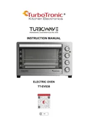
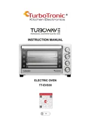
- TurboTronic
- Profilo
- Cosori
- Euromaid
Nyeste Ovn Manualer