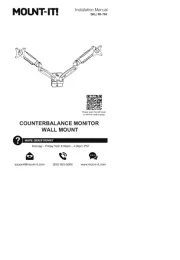
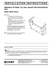
Chief PSS2536B Manual


Læs gratis den danske manual til Chief PSS2536B (2 sider) i kategorien Flad panel støtte. Denne vejledning er vurderet som hjælpsom af 11 personer og har en gennemsnitlig bedømmelse på 4.9 stjerner ud af 6 anmeldelser. Har du et spørgsmål om Chief PSS2536B, eller vil du spørge andre brugere om produktet?

Side 1/2
I N S T A L LA T I O N I N S T R U C T I O N S
Chief Manufacturing, a division of Milestone AV Technologies
8401 Eagle Creek Parkway, Savage, MN 55378
P: 800.582.6480 / 952.894.6280 F: 877.894.6918 / 952.894.6918
8804-000254 RevC
©2008 Milestone AV Technologies
0
5
/08
ALL COMPONENTS MUST BE SECURELY FASTENED TO A
STRUCTURAL MEMBER CAPABLE OF SUPPORTING 4
TIMES THE COMBINED WEIGHT OF ALL COMPONENTS
PLUS THE EQUIPMENT BEING MOUNTED. IF IT CANNOT
SUPPORT THIS WEIGHT, THE STRUCTURE MUST BE
REINFORCED.
THE MAXIMUM WEIGHT TO BE INSTALLED ON THE
MOUNT IS 1
75
POUNDS (
79.38
KG).
PSB-2534 & 2536
DISPLAY MOUNTING BRACKET
Prior to assembly, unpack carton completely and verify contents.
If you are missing any of the following components, please contact Customer Service at 1-800/582-6480
(2) Plasma Side Bracket (2) Plasma Top/Bottom Bracket
(4) Mounting Button - Tapped (8) 10-24 x .5 Button Head Cap Screw
(4) M8 x 35mm Button Head Cap Screw (4) .51 X .32 X .875 Nylon Spacer
(4) M8 x 50mm Button Head Cap Screw (4).68 X .32 X .625
(1) 1/8 Allen Key (1) M5 Allen Key
BEFORE PROCEEDING, READ INSTALLATION INSTRUCTIONS COMPLETELY
DISPLAYS ARE EXTREMELY FRAGILE.
1. Using a 10-24 button head cap screw inserted from back side of bracket, secure mounting button, with
chamfered hole of mounting button (larger surface) facing bracket, to top and bottom brackets (four places)
(see Figure 2 & Figure 3).
Figure 1
WARNING!
Figure 2 Figure 3
2. Using four 10-24 button head cap screws, attach top and bottom to side brackets (see Figure 4 &
Figure 5). The square offset holes can be used if use of the center hole causes the cross brackets to
block connections or if an offset is needed for the installation (See Figure 6 & Figure 7).
3. Place Nylon spacers over mounting holes on back of screen. Attach mounting brackets to display
using M8 screws (see Figures 8 & Figure 9). If needed add both sets of spacers and use the set of
longer bolts to attain required clearance.
4. With the aid of another person, lift your display up to the Chief Mount, aligning buttons of mounting
brackets with slots in the Chief Mount.
5. Lower safety latch on the Chief Mount to secure your display, making sure latch is completely
engaged.
Figure 4 Figure 5
Figure 8 Figure 9
Figure 6 Figure 7


Produkt Specifikationer

Mærke: Chief
Kategori: Flad panel støtte
Model: PSS2536B

Har du brug for hjælp?

Hvis du har brug for hjælp til Chief PSS2536B stil et spørgsmål nedenfor, og andre brugere vil svare dig


Flad panel støtte Chief Manualer

Chief

Chief TS318TU Manual

30 Januar 2025
Chief

Chief TS318SU Manual

30 Januar 2025
Chief

Chief PWCU Manual

15 Januar 2025
Chief

Chief MIWRFUB Manual

15 Januar 2025
Chief

Chief TILD1X5NE1-M Manual

15 Januar 2025
Chief

Chief MWRIWUB Manual

15 Januar 2025
Chief

Chief TILD1X4NE1-R Manual

15 Januar 2025
Chief

Chief TILD1X3NE1-L Manual

15 Januar 2025
Chief

Chief TILD1X3NE1-R Manual

15 Januar 2025
Chief

Chief KPP110B Manual

15 Januar 2025

Flad panel støtte Manualer

Nyeste Flad panel støtte Manualer

Ateca

Ateca VARIATION00376 Manual

26 Februar 2025
Ateca

Ateca ELLIPSE00381 Manual

26 Februar 2025
Ateca

Ateca CRESCENDO00388 Manual

26 Februar 2025
Ateca

Ateca AT247BA Manual

26 Februar 2025
Ateca

Ateca LEDE00224 Manual

26 Februar 2025
Ateca

Ateca UNIQUE00335 Manual

26 Februar 2025
Ateca

Ateca LEGEND00176 Manual

26 Februar 2025
Ateca

Ateca LUXE00281 Manual

26 Februar 2025