CLT- & CLX-2IND/4IND
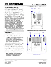
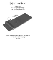
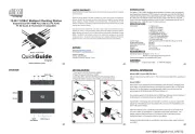
Terminal Block & Module Locations in Single-wide Enclosure
(CLT/CLX-4IND shown)
Functional Summary
TERMINAL BLOCK
(LEFT)
MODULE
GROUNDING
TERMINAL BLOCK
The CLT/CLX-2IND is a 2-inductor terminal block and
module kit while the CLT/CLX-4IND is a 4-inductor
terminal block and module kit. Inductor modules are
typically used to reduce hum from incandescent lamps
that are connected to dimmer modules in a Crestron
lighting system. These kits can be mounted in any
Crestron Automation Enclosure (CAEN-Series
Enclosures). The terminal block is for connecting wires
into and out of the inductor module. The inductor is wired
in series between the output of the dimmer module and
the load. The maximum load for any inductor in the
module is 16 amps.
Each of these Terminal Block and Module kits is
considered single entities and must be used together. The
terminal blocks (CLT-2IND and/or CLT-4IND) are
shipped separately from their respective modules
(CLX-2IND and CLX-4IND) to permit termination of the
field wiring to the terminal block prior to installation of
the module, as described in this guide.
Installation
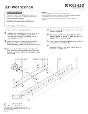
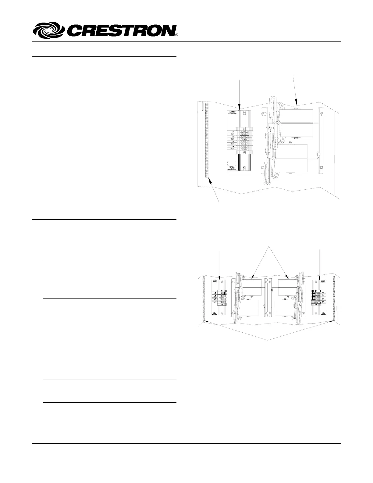
Terminal Block & Module Locations in Double-wide
Enclosure (CLT/CLX-4IND shown)
The terminal block and module must be mounted into a
Crestron Automation Enclosure by a licensed electrician,
in accordance with all national and local codes.
TERMINAL BLOCK
(LEFT)
MODULES
TERMINAL BLOCK
(RIGHT)
GROUNDING
TERMINAL
BLOCKS
CAUTION: This equipment is for indoor use only.
Mount in a well-ventilated area. The ambient
temperature must be 32°F to 104°F (0°C to 40°C).
The relative humidity must be 10% to 90% (non-
condensing).
Terminal blocks are installed along the left side of single-
wide enclosures and along the outside edges (left and
right sides) of double-wide enclosures. Modules are
installed along the right side of single-wide enclosures
and side-by-side in the center of double-wide enclosures.
When installing modules and terminal blocks in a double-
wide enclosure, be sure to invert units on the right side so
that they can be properly wired. Refer to the illustrations
shown in the next column when considering the location
of terminal blocks and modules within an enclosure.
NOTE: Inductor modules and terminal blocks
should be installed above the dimmer modules,
towards the top of the CAEN enclosure.
Crestron Electronics, Inc.
Installation Guide – DOC. 6315
15 Volvo Drive Rockleigh, NJ 07647 11.04
Tel: 888.CRESTRON
Fax: 201.767.7576 Specifications subject to
www.crestron.com change without notice.