Crown SMX-6 Manual
Crown
Ikke kategoriseret
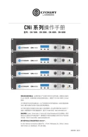
SMX-6
| Mærke: | Crown |
| Kategori: | Ikke kategoriseret |
| Model: | SMX-6 |
Har du brug for hjælp?
Hvis du har brug for hjælp til Crown SMX-6 stil et spørgsmål nedenfor, og andre brugere vil svare dig
Ikke kategoriseret Crown Manualer
9 Oktober 2025
9 Oktober 2025

9 Oktober 2025

8 Oktober 2025
8 Oktober 2025
8 Oktober 2025
8 Oktober 2025
7 Oktober 2025
7 Oktober 2025
16 December 2024
Ikke kategoriseret Manualer
- AMS Office
- Haws
- Nelson
- Paradigm
- Marmitek
- Sortimo
- EtherWAN
- Zurn Wilkins
- Beeletix
- RIX
- Winchester
- Silver Cross
- Gen Energy
- Maxview
- Nebula
Nyeste Ikke kategoriseret Manualer

10 December 2025

10 December 2025

10 December 2025

10 December 2025

10 December 2025

10 December 2025

10 December 2025

10 December 2025

10 December 2025

10 December 2025