GX SERIES SINEWAVE UPS
GX150C2
USER MANUAL
YOUR ULTIMATE ALLY IN POWER
Cyber Power Systems (USA), Inc. 4241 12th Avenue East, Suite 400 | Shakopee, MN 55379 | CyberPowerSystems.com
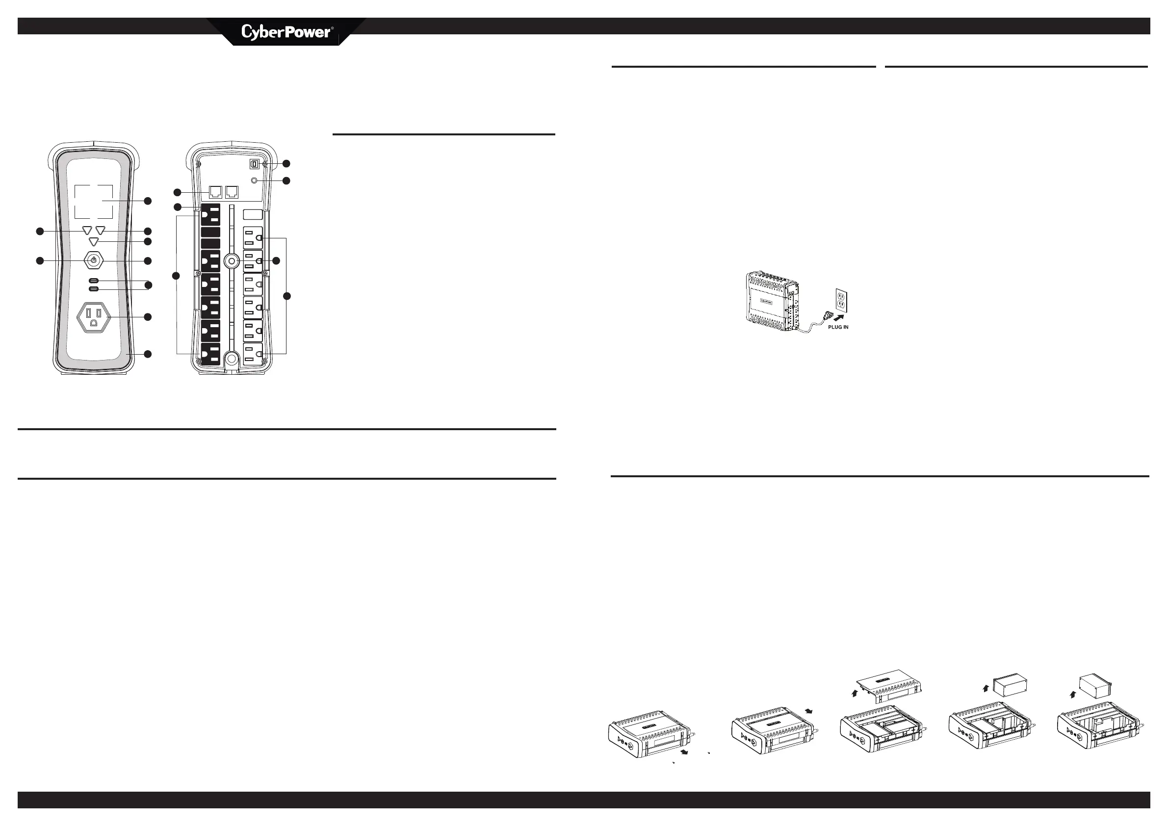
FEATURES
1. Power Button
2. Power On Indicator
3. LCD Display
4. Down/Display Button
5. Up/Mute Button
6. Enter/Setup Button
7. USB-C Charge Ports
8. Battery and Surge Protected Outlets
9. RGB Light Strip
10. Circuit Breaker
11. USB Communication Port
12. Wiring Fault Indicator (red)
13. Communication Protection Ports (RJ45)
14. Transformer-spaced Outlet with Battery Backup and
Surge Protection
15. Full-Time Surge Protection Outlets
Thank you for purchasing a CyberPower product. Please take a few minutes to register your product at: www.cyberpower.com/registration. Registration certifies your product’s warranty,
confirms your ownership in the event of a product loss or theft and entitles you to free technical support. Register your product now to receive the benefits of CyberPower ownership.
CAUTION! To prevent the risk of fire or
electric shock, install in a temperature
and humidity controlled indoor area free
of conductive contaminants. (Please see
specifications for acceptable temperature
and humidity range.)
CAUTION! To reduce the risk of electric
shock, do not remove the cover except to
service the battery. Turn o and unplug
the unit before servicing the batteries.
There are no user serviceable parts inside
except for the battery.
CAUTION! Hazardous live parts inside can
be energized by the battery even when
the AC input power is disconnected.
CAUTION! The UPS must be connected
to an AC power outlet with fuse or circuit
breaker protection. Do not plug into an
outlet that is not grounded. If you need to
de-energize this equipment, turn o and
unplug the unit.
CAUTION! To avoid electric shock, turn
o the unit and unplug it from the AC
power source before installing a computer
component.
CAUTION! To reduce the risk of fire,
connect only to a circuit provided with
20 amperes maximum branch circuit over
current protection in accordance with the
National Electric Code, ANSI/NFPA 70.
CAUTION! Not for use in a computer
room as defined in the Standard for the
Protection of Electronic Computer/Data
Processing Equipment, ANSI/NFPA 75.
CAUTION! Do not dispose of batteries in a
fire. The batteries may explode.
CAUTION! Do not open or mutilate
batteries. Released electrolyte is harmful
to the skin and eyes. It may be toxic.
DO NOT USE FOR MEDICAL OR LIFE
SUPPORT EQUIPMENT! CyberPower
Systems does not sell products for life
support or medical applications. DO
NOT use in any circumstance that would
aect operation and safety of life support
equipment, any medical applications or
patient care.
DO NOT USE WITH OR NEAR
AQUARIUMS! To reduce the risk of fire
or electric shock, do not use with or near
an aquarium. Condensation from the
aquarium can cause the unit to short out.
DO NOT USE THE UPS ON ANY
TRANSPORTATION! To reduce the risk
of fire or electric shock, do not use
the unit on any transportation such as
airplanes or ships. The eect of shock or
vibration caused during transit and the
damp environment can cause the unit to
short out.
PRODUCT REGISTRATION
IMPORTANT SAFETY WARNINGS (SAVE THESE INSTRUCTIONS)
This manual contains important instructions that should be followed during installation
and maintenance of the UPS and batteries. Please read and follow all instructions
carefully during installation and operation of the unit. Read this manual thoroughly
before attempting to unpack, install, or operate your UPS.
INSTALLING YOUR UPS SYSTEM - Continued
HARDWARE INSTALLATION GUIDE
INSTALLING YOUR UPS SYSTEM
1. Your new UPS may be used
immediately upon receipt. However,
after receiving a new UPS, to ensure
the battery’s maximum charge
capacity, it is recommended that
you charge the battery for at least 8
hours. Your UPS is equipped with an
auto-charge feature. When the UPS is
plugged into an AC outlet, the battery
will automatically charge whether the
UPS is turned on or o.
Note: This UPS is designed with a
safety feature to keep the system
from being turned on during
shipment. The first time you turn
the UPS on, you will need to have it
connected to AC power or it will not
power up.
2. With the UPS unit turned o and
unplugged, connect your computer,
monitor, and any other peripherals
requiring battery backup into the
battery power supplied outlets. Plug
the other peripheral equipment (eg.
printer, scanner, speakers, etc.) into
the full time surge protection outlets.
DO NOT plug a laser printer, paper
shredder, copier, space heater,
vacuum, sump pump or other large
electrical devices into the “Battery
and Surge Protected Outlets”. The
power demands of these devices may
overload and damage the UPS.
3. Plug the UPS directly into a 2-pole,
3-wire grounded receptacle (wall
outlet). Make sure the wall branch
outlet is protected by a fuse or
circuit breaker and does not service
equipment with large electrical
demands (e.g., air conditioner, copier,
etc.). The warranty prohibits the use
of extension cords, outlet strips, and
surge strips in conjunction with the
UPS unit.
4. Press the power switch to turn the unit
on. The Power On indicator light will
illuminate and the unit will “beep”.
5. If an overload is detected, an audible
alarm will sound and the unit will emit
one long beep. To correct this, turn
the UPS o and unplug at least one
piece of equipment from the battery
power supplied outlets. Make sure the
circuit breaker is depressed and then
turn the UPS on.
6. To maintain optimal battery charge,
leave the UPS plugged into an AC
outlet at all times.
7. To store the UPS for an extended
period, cover it and store with the
battery fully charged. While in storage,
recharge the battery every three
months to ensure battery life.
8. Ensure the wall outlet and UPS are
located near the equipment being
attached for proper accessibility.
BASIC OPERATION
1. Power Button: Used as the master on/
o switch for equipment connected to
the battery power supplied outlets.
2. Power On Indicator: This LED is
illuminated when the utility power
is normal and the UPS outlets are
providing power, free of surges and
spikes.
3. LCD Display: High resolution and
intelligent LCD display shows all the
UPS information using icons and
messages. For more information please
review the “Definitions for Illuminated
LCD Indicators” section below.
4. Down/Display Button: The button
can be used to select the LCD display
contents including Input Voltage,
Output Voltage, and Estimated Run
Time. Short press the button to scroll
down the function menu. Pressing the
button for two seconds will keep the
LCD display always on or turn the LCD
display o while in AC/Utility power
mode. For more information about the
Down/Display Button, please refer to
the Function Setup Guide.
5. Up/Mute Button: Short press the
button to scroll up the function menu.
Holding the button for more than two
seconds will silence the alarm. For
more information about the Up/Mute
Button, please refer to the Function
Setup Guide.
6. Enter/Setup Button: Press the button
for two seconds to enter the setup
menu and then select the functions for
configuration. For more information
about the Enter/Setup Button, please
refer to the Function Setup Guide.
7. USB-C Charge Ports:
USB-C (upper) Output : 5Vdc, 2.5A
Max / 9Vdc, 2A Max / 15Vdc, 2A Max
USB-C (lower) Output : 5Vdc, 2.4A Max
Total USB Output: 30W Max
8. Battery and Surge Protected Outlets:
The unit has seven battery powered
and surge protected outlets to ensure
temporary uninterrupted operation of
your equipment during a power failure.
(DO NOT plug a laser printer, paper
shredder, copier, space heater, vacuum
cleaner, sump pump, or other large
electrical device into the “Battery and
Surge Protected Outlets.” The power
demands of these devices will overload
and possibly damage the unit.)
9. RGB Light Strip: There are 12 light
bar modes available, allowing you to
choose from a variety of colors and
eects to personalize your setup.
For more information about RGB setup,
please refer to the RGB Lighting Quick
Start Guide.
10. Circuit Breaker: Located on the back
of the UPS, the circuit breaker provides
overload and fault protection.
11. USB Communication Port: Allows
communication between the USB port
on the computer and the UPS unit.
12. Wiring Fault Indicator (red): This
LED indicator will illuminate to warn
the user that a wiring problem exists,
such as bad ground, missing ground or
reversed wiring. If this is illuminated,
disconnect all electrical equipment
from the outlet and have an electrician
verify the outlet is properly wired.
The unit will not provide surge
protection without being plugged
into a grounded and properly wired
wall outlet.
13. Communication Protection Ports
(RJ45): Bi-directional communication
ports provide surge protection to a
10/100/1000 Ethernet connection.
*Not for telecommunication
(telephone) network.
14. Transformer-spaced Outlet with
Battery Backup and Surge Protection:
The UPS unit has a widely-spaced
outlet, so the AC power adapter can
be plugged into the UPS without
overlapping or blocking adjacent
outlets.
15. Full-Time Surge Protection Outlets:
The unit has six outlets that provide
surge suppression without battery
backup.
UNPACKING
Inspect the UPS upon receipt.
The box should contain the following:
(a) UPS
(b) User’s manual
(c) USB A+B type cable
(d) Function Setup Guide
(e) RGB Quick Start Guide
*PowerPanel® software is available
on our website. Please visit www.
cyberpower.com and go to the
Software Section for free download.
SUPPORTS ACTIVE PFC
POWER SUPPLIES
This CyberPower UPS system supports
High Eciency power supplies with
Active Power Factor Correction (Active
PFC). Active PFC is used to improve the
eciency of power delivery. The current
US Energy Star® Program Requirements
for Computers (version 7.1) mandates
Active PFC for all power supplies over
100 watts. Additionally, programs such
as 80 Plus® are often used to identify
high eciency power supplies with
Active PFC.
OVERVIEW
The GX150C2 provides complete power
protection from utility power that is not
always consistent and features 1445
Joules of surge protection. All units
provide long lasting battery backup
during power outages with maintenance
free batteries. The GX150C2 ensures
consistent power to your computer
system and includes software that will
automatically save your open files and
shutdown your computer system during
a utility power loss.
AUTOMATIC VOLTAGE REGULATOR
The GX150C2 uses Automatic
Voltage Regulation (AVR) to stabilize
inconsistent utility power voltage
to levels that are safe for connected
equipment. AVR safeguards
hardware and important data files by
automatically increasing low utility
power to a consistent and safe output
voltage while preserving battery power
for outages.
DETERMINE THE POWER
REQUIREMENTS OF YOUR EQUIPMENT
1. Ensure that the equipment plugged
into the UPS does not exceed the
UPS unit’s rated capacity. If the
rated capacities of the unit are
exceeded, an overload condition
may occur and cause the UPS unit
to shut down or the circuit breaker
to trip.
2. There are many factors that
can aect the amount of power
that your electronic equipment
will require. For optimal system
performance keep the load below
80% of the unit’s rated capacity.
Replacement of batteries located in an OPERATOR ACCESS AREA.
1. When replacing batteries, replace with the same number of the following battery:
CyberPower / RB1290X2
*Each purchase of RB1290X2 includes 2 units of RB1290.
2. CAUTION! Risk of Energy Hazard, 24V, maximum 9 Ampere-hour battery. Before
replacing batteries, remove conductive jewelry such as chains, wrist watches, and
rings. High energy conducted through these materials could cause severe burns.
3. CAUTION! Do not dispose of batteries in a fire. The batteries may explode.
4. CAUTION! Do not open or mutilate batteries. Released material is harmful to the
skin and eyes. It may be toxic.
5. CAUTION! A battery can present a risk of electrical shock and high short circuit
current. The following precautions should be observed when working on batteries:
1) Remove watches rings, or other metal objects.
2) Use tools with insulated handles.
CAUTION - RISK OF EXPLOSION IF BATTERY IS REPLACED BY AN INCORRECT TYPE.
REMINDER: Batteries are considered HAZARDOUS WASTE and must be disposed of
properly. Most retailers that sell lead acid batteries collect used batteries for recycling,
as required by local regulations.
BATTERY REPLACEMENT PROCEDURE
1. Turn o and unplug all connected equipment.
2. Turn the UPS o and unplug it from the AC power source.
3. Turn the UPS on its side.
4. Remove the front panel retaining screws located on the bottom of the UPS.
5. Slide the front panel completely o of the unit.
6. Remove the batteries from the compartment.
7. Disconnect the battery wires from the batteries.
8. Place a new battery into the left compartment. Attach the yellow wire to the battery’s
black terminal and the red wire to the battery’s red terminal.
9. Place a new battery into the right compartment. Attach the yellow wire to the
battery’s red terminal and the black wire to the battery’s black terminal.
Note: Only use new batteries for replacement and both batteries should be replaced
at the same time to ensure maximum life span.
10. Put the batteries back into the compartment.
11. Slide back the battery compartment cover and tighten the retaining screws.
12. Recharge the UPS for 8-16 hours to fully charge the battery.
REPLACING THE BATTERY
PLUG IN
K01-0001124-01
3
11
5
6
1
8
9
7
12
15
13
8
10
14
9
4
2