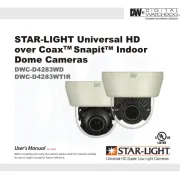
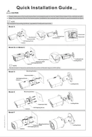
Dahua Technology DH-SD22204UE-GN-W Manual
Dahua Technology
Overvågningskamera
DH-SD22204UE-GN-W
Læs gratis den danske manual til Dahua Technology DH-SD22204UE-GN-W (185 sider) i kategorien Overvågningskamera. Denne vejledning er vurderet som hjælpsom af 41 personer og har en gennemsnitlig bedømmelse på 4.9 stjerner ud af 21 anmeldelser. Har du et spørgsmål om Dahua Technology DH-SD22204UE-GN-W, eller vil du spørge andre brugere om produktet?
Side 1/185

Network Speed Dome & PTZ Camera
User’s Manual
Web 3.0
V2.0.0

I
Foreword
General
The manual introduces the functions and operations of the web interface of the network speed
dome and PTZ camera (hereinafter referred to "the Device").as
Safety Instructions
The following categorized signal words with defined meaning might appear in the manual.
Signal Words
Meaning
Indicates a high potential hazard which, if not avoided, will result
in death or serious injury.
Indicates a medium or low potential hazard which, if not
avoided, could result in slight or moderate injury.
Indicates a potential risk which, if not avoided, could result in
property damage, data loss, lower performance, or
unpredictable result.
Provides methods to help you solve a problem or save you time.
Provides additional information as the emphasis and
supplement to the text.
Revision History
Version
Revision Content
Release Time
V2.0.0
Add some functions of the
Baseline, and refine the whole
manual.
January 2020
V1.1.1
Update some functions of Security
Baseline.
September 2019
V1.0.0
First release.
May 2018
About the Manual
The manual is for reference only. If there is inconsistency between the manual and the
actual product, the actual product shall prevail.
We are not liable for any loss caused by the operations that do not comply with the manual.
The manual would be updated according to the latest laws and regulations of related
regions. For detailed information, see the paper manual, CD ROM, QR code or our official -
website. If there is inconsistency between paper manual and the electronic version, the
electronic version shall prevail.

II
All the designs and software are subject to change without prior written notice. The product
updates might cause some differences between the actual product and the manual. Please
contact the customer service for the latest program and supplementary documentation.
There still might be deviation in technical data, functions and operations description, or
errors in print. If there is any doubt or dispute, please refer to our final explanation.
Upgrade the reader software or try other mainstream reader software if the manual (in PDF
format) cannot be opened.
All trademarks, registered trademarks and the company names in the manual are the
properties of their respective owners.
Please visit our website, contact the supplier or customer service if there is any problem
occurred when using the device.
If there is any uncertainty or controversy, please refer to our final explanation.

III
Important Safeguards and Warnings
The manual will help you to use the Device properly. Read the manual carefully before using
the Device, and keep it well for future reference.
Operation Requirements
Avoid heavy stress, violent vibration, and water splash during transportation, storage, and
installation. Complete package is necessary during the transportation. We assume no
responsibility for any damage or problem caused by the incomplete package during the
transportation.
To avoid damage, protect the Device from falling down and heavy vibration. Arrange more
than one person to move the Device when necessary.
Buckle the safety hook before installing the Device if it is included.
Keep the Device away from devices that generate electromagnetic field like televisions,
radio transmitters, electromagnetic devices, electric machine, transformers, and speakers;
otherwise image quality will be influenced.
Keep the Device away from smoke, vapor, heat, and dust.
Do not install the Device near heating furnace, spotlight, and other heat sources. If it is
installed on ceiling, in kitchen or near boiler room, the Device temperature might rise.
Do not dissemble the Device; otherwise it might cause dangers or device damage. Contact
your local retailer or customer service center for internal setup or maintenance
requirement.
Make sure that there is no metal, or inflammable, explosive substance in the Device;
otherwise it might cause fire, short circuit, or other damage. Power off the Device -and
disconnect the power cord immediately if there is water or liquid falling into the Device. And
contact your local retailer or customer service center. Avoid sea water or rain eroding the
Device.
Avoid aiming the lens at intense light source, including sunlight, and incandescent light;
otherwise the lens might be damaged.
Clean the enclosure with soft cloth. To remove the dirt, you can dip the soft cloth in proper
detergent, wring the soft cloth out, and then dry the enclosure with soft cloth. Do not use
gasoline, paint thinner, or other chemicals to clean the enclosure; otherwise it might result
in enclosure transfiguration or paint flake. Read all the manuals included before using
chemical cloth. Avoid long time touch between the plastic or rubber material and the
enclosure; otherwise it might result in device damage and paint flake.
It is recommended to use the Device with a lightning proof device for better lightning proof - -
effect.

IV
Requirements for Installation and Maintenance Personnel
Have certificates or experiences related to installation and maintenance of the
closed circuit television (CCTV), and have certificates related to working at height.-
Have basic knowledge and installation skills of CCTV system.
Have basic knowledge and operation technique for low voltage wiring and low voltage - -
electronic circuit connection.
Have the ability to read and understand the manual.
Requirements for Lifting the Device
Use secure lifting appliances suitable for the installation place and the product installation
mode.
Make sure that the selected tools reach the installation height have high safety and
performance.
All installation and operations shall conform to local electrical safety regulations.
The power source shall conform to the requirements of the Safety Extra Low Voltage
(SELV) standard, and supply power with rated voltage which conforms to Limited Power
Source requirement according to IEC60950 1. Note that the power supply requirement is -
subject to the device label.
Use the power adapter recommended by the manufacturer.
For the Device that supports laser, do not aim the laser directly at eyes. And keep a proper
distance from the flammable to avoid fire.
Do not connect several devices to one power adapter; otherwise it might result in overheat
or fire if it exceeds the rated load.
Make sure that the power is off when you connect the cables, install or uninstall the Device.
Power off the Device and disconnect the power cord immediately if there is any smoke,
disgusting smell, or noise from the Device. And contact your local retailer or customer
service center.
Contact your local retailer or customer service center if the Device is abnormal. Do not
disassemble or repair the Device by yourself. We assume no responsibility for any
problems caused by unauthorized modifications, disassembly or repair, incorrect
installation or use, and overuse of certain components.

V
Table of Contents
Foreword .................................................................................................................................................. I
Important Safeguards and Warnings ................................................................................................... III
1 Network Configuration ........................................................................................................................ 1
Network Connection .................................................................................................................... 1
Logging in to the Web Interface ................................................................................................... 1
1.2.1 Device Initialization ...........................................................................................................1
1.2.2 First Time Login ................................................................................................................. 5
1.2.3 Device Login ..................................................................................................................... 6
1.2.4 Resetting Password .......................................................................................................... 7
2 Live ....................................................................................................................................................... 9
Encoding Setting ......................................................................................................................... 9
Video Window Adjustment ......................................................................................................... 10
stem MenuSy ............................................................................................................................ 15
Video Window Functions ........................................................................................................... 15
PTZ Configuration ..................................................................................................................... 18
PTZ Status ................................................................................................................................ 22
3 AI Live ................................................................................................................................................. 24
AI Live Interface......................................................................................................................... 24
3.1.2 Information Display Area of Detected Targets ................................................................. 24
3.1.3 Snapshot Display Area .................................................................................................... 25
3.1.4 Statistics Area of the Detected Targets ............................................................................ 25
AI Live Settings .........................................................................................................................26
4 Playback ............................................................................................................................................. 28
Video Playback .......................................................................................................................... 28
4.1.1 Video Play Function Bar .................................................................................................. 29
4.1.2 Recording Type ............................................................................................................... 29
4.1.3 Auxiliary Functions .......................................................................................................... 29
4.1.4 Video Playback File Search and Display Area ................................................................30
4.1.5 Video Clipping Area ......................................................................................................... 33
4.1.6 Progress Bar Time Formats ............................................................................................ 33
Picture Playback ........................................................................................................................ 34
4.2.1 Picture Playing Functions ................................................................................................ 34
4.2.2 Picture Playback File Search and Display Area ..............................................................35
4.2.3 Snapshot Types ..............................................................................................................36
5 Setting ................................................................................................................................................ 37
Camera .....................................................................................................................................37
5.1.1 Conditions Settings ......................................................................................................... 37
5.1.2 Video ............................................................................................................................... 53
5.1.3 Audio ............................................................................................................................... 62
Network Settings ....................................................................................................................... 64
5.2.1 TCP/IP ............................................................................................................................. 64
5.2.2 Port . ................................................................................................................................ 66
5.2.3 PPPoE ............................................................................................................................68

VI
5.2.4 DDNS .............................................................................................................................. 69
5.2.5 SMTP (Email) .................................................................................................................. 70
5.2.6 UPnP ............................................................................................................................... 73
5.2.7 SNMP .............................................................................................................................. 74
5.2.8 Bonjour ............................................................................................................................ 76
5.2.9 Multicast .......................................................................................................................... 77
5.2.10 Auto Register ................................................................................................................. 78
5.2.11 Wi-Fi .............................................................................................................................. 79
5.2.12 802.1x ........................................................................................................................... 80
5.2.13 QoS ............................................................................................................................... 81
5.2.14 4G ................................................................................................................................. 82
5.2.15 Access Platform ............................................................................................................85
PTZ Settings .............................................................................................................................88
5.3.1 Protocol ........................................................................................................................... 88
5.3.2 Function .......................................................................................................................... 89
Event Management ................................................................................................................. 100
5.4.1 Video Detection ............................................................................................................. 100
5.4.2 Smart Motion Detection ................................................................................................. 106
5.4.3 Audio Detection ............................................................................................................. 107
5.4.4 Smart Plan .................................................................................................................... 109
5.4.5 IVS ................................................................................................................................ 110
5.4.6 Face Recognition .......................................................................................................... 116
5.4.7 People Counting ............................................................................................................ 126
5.4.8 Heat Map....................................................................................................................... 127
5.4.9 Video Metadata ............................................................................................................. 129
5.4.10 Alarm ........................................................................................................................... 133
5.4.11 Abnormality .................................................................................................................. 133
Storage .................................................................................................................................... 138
5.5.1 Schedule ....................................................................................................................... 138
5.5.2 Snapshot by Location .................................................................................................... 141
5.5.3 Destination .................................................................................................................... 142
5.5.4 Record Control .............................................................................................................. 145
System Management .............................................................................................................. 146
5.6.1 Device Settings ............................................................................................................. 146
5.6.2 Account Settings ........................................................................................................... 148
5.6.3 Safety ............................................................................................................................ 154
5.6.4 Peripheral ...................................................................................................................... 165
5.6.5 Default ........................................................................................................................... 166
5.6.6 Import/Export ................................................................................................................. 166
5.6.7 Auto Maintain ................................................................................................................ 167
5.6.8 Upgrade ........................................................................................................................ 168
Information .............................................................................................................................. 168
5.7.1 Version .......................................................................................................................... 168
5.7.2 Log Information ............................................................................................................. 169
5.7.3 Online User ................................................................................................................... 171
5.7.4 Life Statistics ................................................................................................................. 171
6 Alarm ................................................................................................................................................ 172

VII
7 Logout .............................................................................................................................................. 174
Cybersecurity Recommendations ................................................................................ 175

1
1 Network Configuration
Network Connection
To view the web interface on your PC, connect the Device to the PC first. There are mainly two
connection modes between the Device and PC. See Figure 1 1 Figure 1 2.-and -
Direct connection by using a network cable
Connection over by using switch or routera
The models presented in the figures are for reference only, and the actual product shall prevail.
All devices have the same IP address (192.168.1.108 by default) when they are delivered out of
factory. To make the device get access to network smoothly, plan available IP segment
reasonably according to practical network environment.
Logging in to the Web Interface
1.2.1 Device Initialization
For first time use or after you have restored the Device to defaults, you need to initialize the -
Device by performing the following steps.
Open the browser, enter the IP address of the Device in the address bar, and then
press the Enter key.

2
The interface is displayed. Set the Country/Region Setting Country/Region,
Language Video Standard and as needed. See Figure 1 3.-
Country/region setting interface
Click , and the interface is displayed. Save Time Zone Setting
Configure time parameters. See Figure 1 4.-
Time zone setting interface
Click .Next
The interface is displayed. For the interface, see Figure 1 5. For Device Initialization -
the parameter description, see Table 1 1.-

3
Device initialization
Table 1-1 Device initialization parameter description
Parameter
Description
Username
It is admin by default.
Password
The password should consist of 8 to 32 blank characters and contain non-
at least two types of characters among upper case, lower case, number,
and special characters (excluding ' " ; : &). Set a high security password
according to the prompt of password strength. Make sure that the new
password is the same as the confirming password.
Confirm
Password
Enter the confirming password that shall be the same as the password you
entered.
Email Address
Set the email address which is used to reset password.
Email address is enabled by default. You can disable the function as
needed.
Click .Save
The interface is displayed. See Figure 1 6.P2P -

4
P2P interface
Scan the QR code on the interface, download the app, and then finish configurations
according to the instructions on your mobile device. After that, click .Next
The interface is displayed. See Figure 1 7.Online Upgrade -
Online upgrade
Select check box as needed.Auto check for updates-
After the function is enabled, the Device will check for updates once a day automatically.
There will be system notice if any update is available.
- Click , and the login interface is displayed. See Figure 1Next 8.

5
Login interface
1.2.2 - First time Login
You need to download and install the plug in for the first time login.- -
Open the browser, enter the IP address of the Device in the address bar, and then
press the Enter key.
Enter the username and password, and then click .Login
The web interface is displayed.
If you enter the wrong password for 5 times, the account will be locked for 5
minutes. After the locked time, you can log the web interface again.in to
You can set the number of allowed password attempts and locked time in
"5.4.11.3 Illegal Access."
- -Download and install the plug in according to the on screen instruction after logging in
to the web interface. See Figure 1 9.-
- Installing the plug in
-After the plug in is installed, the web interface will be refreshed automatically, and the
video is displayed in interface. See Figure 1 .Live -10

6
Live interface
The interface shown in the manual is for reference only, and the actual interface shall Live
prevail.
1.2.3 Device Login
Open the browser, enter the IP address of the Device in the address bar, and then
press the Enter key.
The interface is displayed. See Figure 1 .Login -11
Device login
Enter the username and password, and then click .Login
The web interface is displayed, and the video is display in interface.ed Live
If you enter the wrong password for 5 times, the account will be locked for 5
minutes. After the locked time, you can log the web interface again.in to
You can set the number of allowed password attempts and locked time. For
details, see "5.4.11.3 Illegal Access."

7
1.2.4 Resetting Password
If you forget the password of the admin user, you can set the password through the provided
email address.
Before resetting the password, you need to provide the email address in advance. For details,
see "1.2.1 Device Initialization" or "5.6.3.2 System Service."
Open the browser, enter the IP address of the Device in the address bar, and then
press the Enter key.
The interface is displayed. See Figure 1 .Login -12
Login
- Click , and the interface is displayed. See Figure 1Forgot password? Prompt 13.
Prompt
Click to reset the password. The OK Reset the password (1/2) interface is displayed.
If you click , your email address, MAC address, device serial number, and other OK
information might be collected.

8
Resetting the password (1)
Scan the QR code on the actual interface according to the instructions, and then enter
the security code received in the mailbox.
Reset the password with the security code you received within 24 hours, otherwise the
code will be invalid.
Click .Next
The interface is displayed. See Figure 1 .Reset the password (2/2) -15
Resetting the password (2)
Set the password of the admin user again.
The password should consist of 8 to 32 non blank characters and contain at least two -
types of characters among upper case, lower case, number, and special characters
(excluding ' " ; : &). Set a high security password according to the prompt of password
strength.
Click .Save

9
2 Live
Click the tab, and t interface is displayed. See Figure 2 1.Live he Live -
Live interface
For descriptions of function bars on the interface, see Table 2 1. Live -
Table 2-1 Function bars description
No.
Description
1
Encoding setting
2
Video window adjustment
3
System menu
4
Video window functions
5
PTZ configuration
6
PTZ status
Encoding Setting
Some devices do not support two sub streams.
For the encoding setting area, See Figure 2 2. For the parameter description, see Table 2 2.- -
Encoding setting

10
Table 2-2 Encoding setting parameter description
Parameter
Description
Main Stream
It has large bit stream value and image with high resolution, but requires
large bandwidth. This option can be used for storage and monitoring.
Sub Stream 1
It has small bit stream value and smooth image, and requires little
bandwidth. This option is normally used to replace main stream when
bandwidth is not enough.
Sub Stream 2
It has small bit stream value and smooth image, and requires little
bandwidth. This option is normally used to replace main stream when
bandwidth is not enough.
Protocol
Select a protocol for video monitoring. The supported protocols include
TCP (Transmission Control Protocol), UDP (User Datagram Protocol), and
Multicast.
Video Window Adjustment
For the video window adjustment bar, See Figure 2 3. For parameter description, see Table -
2 3.-
Video window adjustment
Table 2-3 Video window adjustment parameter description
No.
Parameter
Description
1
Image Adjustment
Click this button, and the interface is Image Adjustment
displayed on the right side of the interface. You can Live
adjust parameters such as brightness, contrast, hue, and
saturation on the interface.
2
Original Size
Adjust the video image to original size.
3
Full Screen
Click this button, and the video is displayed in full screen.
To exit full screen, double click the screen or press the Esc -
button.
4
W:H
Adjust the video image to original ratio or a proper window.
5
Fluency
Click this button, and you can select Realtime, General, or
Fluent General. is selected by default.
6
Rules Info
Click this button, and smart rules are displayed on the Live
interface after the function is enabled. The function is

11
No.
Parameter
Description
enabled by default.
7
PTZ
Click this button, and configurations are displayed on PTZ
the interface after the function is enabled.Live
8
Face
Click this button, and face pictures are displayed on the
screen. See Figure 2 8.-
9
Video Metadata
Click this button, and information about motor vehicles,
non-motor vehicles, and people is displayed on the screen
in real time. See Figure 2 .-11
10
Anti aliasing-
Click this button to enable anti aliasing, and then aliasing -
can be avoided when video windows are small.
11
Panorama
Click this button, and a panorama window is displayed on
the interface. You can perform operations such as Live
positioning, calling presets, and setting tours.
Image Adjustment
For Image Adjustment interface, s Figure 2 4. For parameter description, see Table 2 4.ee - -
Image Adjustment
Table 2-4 Image adjustment parameter description
Parameter
Description
Adjust the image brightness.
Adjust the image contrast.
Adjust the image hue.
Adjust the image saturation.
Restore brightness, contrast, saturation and hue to default values.

12
Only brightness, contrast, hue, and saturation of live view image on the web interface can be
adjusted with this function. To adjust the brightness, contrast, hue, and saturation of the Device,
you can go to .Setting > Camera > Conditions
Panorama
For the interface, see Figure 2 5.Panorama -
Panorama interface
You can perform positioning in this window by drawing a box with the left mouse button.
The located area is displayed on the interface and enlarged.Live
After you click the Device rotates from 0 to 360 degrees horizontally and from 6 Refresh,
to 65 degrees vertically to obtain a new panoramic image.
You can adjust the size of the panoramic image by dragging the screen ratio bar
.
You can click to call a corresponding preset on the right side of the window. For
the interface, see Figure 2 6. For how to set a preset, see "5.3.2.1 Preset-."
Preset
You can click to call a corresponding tour on the right side of the window. For the
interface, see Figure 2 7. For how to set a tour, see "5.3.2.2 Tour-."

13
Tour
Face
For the interface, see Figure 2Face -8. Face recognition result is displayed on the left side, and
the captured face picture and attributes are displayed on the right side.
Face
Face recognition result display area: Displays the captured small face pictures, the
corresponding face pictures in the database, and the similarities between them. After you
click the picture, the attributes and details are displayed. See Figure 2 9.-

14
Face recognition result display
Face and attributes display zone: Displays the captured small face pictures and
information such as gender, age, and expression. After you click the picture, the details are
displayed. See Figure 2 .-10
Face and attributes display
Video Metadata
For the interface, see Figure 2 . Motor vehicle information is displayed on the right side, and -11
the information about human and non motor vehicles is at the bottom of the interface. For more -
details, see "5.4.9 Video Metadata."

15
Video metadata
System Menu
To access an interface, click the corresponding tab on the system menu. For the system menu,
see Figure 2 .-12
System menu
Video Window Functions
For the video window function buttons, See Figure 2 . For the parameter description, see -13
Table 2 5.-
Video window function buttons
Table 2-5 Video window function button description
No.
Parameter
Description
1
Wiper Control
Click this button to select wiper operation.
Start: Click this button, and the wiper starts and waves
continuously.
Stop: Click this button, and the wiper is turned off and stops
waving.
Once: Click this button, and the wiper starts and waves from

16
No.
Parameter
Description
left to right for one time.
2
Mark
Click this button, right click on the interface, and the -Live
function menu is displayed. See Figure 2 . You can add -14
information on the interface, and also manage added Live
comments.
Add Info: Select from the pop up menu, and Add Info -
enter the comment. For the interface, see Figure 2 .-15
Managing comments: Select from Info Management
the pop up menu to display, hide, or delete added -
comments. For the interface, see Figure 2 .-16
3
Regional Focus
Click the button, draw a box with the mouse on the live view,
and then the Device will automatically focus on the area in
the box.
4
Relay-out
Click the button, and an alarm will be triggered. When an
alarm is triggered, the icon turns red; and when an alarm is
canceled, the icon turns grey.
5
Gesture Control
Click the button, and you can drag the live view by pressing
and holding the left mouse button to control PTZ; and you
can also zoom in or out through the mouse wheel.
6
Digital Zoom
Click the button, and then select an area in the live view
to zoom in; right click on the image to restore to the -
original status. In enlarged status, drag the image to
check other area.
Click the button, and then scroll the mouse wheel in the
live view to zoom in or out.
7
Snapshot
Click the button to capture one picture of the current image,
and it will be saved to the live snapshot storage path set in
"5.1.2.5 Path."
8
Triple Snapshot
Click the button, and three pictures of the current image are
captured with one snapshot per second. These snapshots
will be saved to the live snapshot storage path set in "5.1.2.5
Path."
9
Record
Click the button to record videos. The recording will be
saved to the live recording storage path set in "5.1.2.5
Path."
10
Manual Track
Click the button and select any area by dragging the left
mouse button in the video window; the Device tracks objects
in this area intelligently.
11
Audio
Click the button to enable or disable audio output of the
monitoring stream.
Before using the function, you need to enable the audio of
the corresponding stream in Setting > Camera > Audio
first.
12
Talk
Click the button to enable or disable the two way audio.-

17
Mark—menu
Mark—adding comments

18
Mark—managing comments
PTZ Configuration
You can control PTZ by using the panel or joystick. You can also set preset, PTZ Control
scanning, and other functions in the PTZ Function area.
PTZ Control
Before using the , you need to set the PTZ protocol by selecting PTZ Control panel Setting >
PTZ > Protocol.
For panel, See Figure 2 . For parameter description, see Table 2 6.PTZ Control -17 -

19
PTZ control
Table 2-6 PTZ control parameter description
No.
Parameter
Description
1
Direction buttons
There are 8 directions: Up, down, left, right, upper left, upper
right, lower left, and lower right.
2
Position
Provides quick positioning function. Draw an box in the live
view with the mouse, and then the PTZ rotates to and
focuses on the selected area rapidly.
3
Speed
The changing speed of PTZ direction. The higher the value,
the faster the speed.
4
Zoom/Focus/Iris
Click to increase the value, and click to
decrease the value.
Joystick
You can drag the middle button to simulate joystick operations to control device rotation. For
the operation interface, see Figure 2 . Speed, zoom, focus, and iris configurations are the -18
same as that of panel.PTZ Control

20
Joystick
PTZ Functions
The PTZ supports multiple functions. Select a function, click to start or
using the function, and then click to stop using the function. For the configuration
interface, see Figure 2 . For the supported functions and settings, see Table 2 7.-19 -
PTZ function
Table 2-7 PTZ functions description
Parameter
Description
Scan
Select from the list, enter a scan number, and then click . The PTZ Scan Start
starts scanning, and the default number is 1.
Preset
Select from the list, enter a preset number, and then click . The Preset Go to
PTZ will rotate to the preset position.
Tour
Select Tour from the list, enter a tour number, and then click . The PTZ Start
starts to tour.

21
Parameter
Description
Pattern
Select from the list, enter a pattern number, and then click Pattern Start. The
PTZ starts to pattern.
Assistant
Reserved for special requirements.
If necessary, enable this function under the guidance of professionals.
Pan
Select from the list, and then click . The PTZ starts to pan.Pan Start
Go to
Select from the list, enter horizontal angle value, vertical angle Go to
value and zoom, and then click Go to. The Device will turn to the position
you want.
One unit of the horizontal angle value or vertical angle value you enter
equals 0.1 degree.
Menu
For the menu interface, see Figure 2 . For the parameter description, see Table 2 8.-20 -
Menu interface
Table 2-8 Menu parameter description
Parameter
Description
Direction
buttons
Click the up and down buttons to select parameters, and click the left and
right buttons to select parameter values.
OK
Confirmation button.
Open
Open the OSD menu.
Close
Close the OSD menu.
Click to open the OSD menu. The OSD menu is displayed on the live view. See Figure Open
2 .-21

22
OSD menu
You can finish the following settings through the menu:
Camera settings: See "5.1 Camera."
PTZ settings: See "5.3 PTZ Settings."
System management: See "5.6 System Management."
You can change the location of the OSD menu in "5.1.2.3 Overlay."
PTZ Status
On the interface, the PTZ status is displayed at the lower right corner. See Figure 2 .Live -22
The function is available on select models.
PTZ status
When the PTZ lifespan is close to the threshold, the warning will be displayed on the Live
interface. See Figure 2 Figure 2 .-23 and -24
Warning (1)

23
Warning (2)

24
3 A iveI L
You can check the information of the detected human faces, human bodies, motor vehicles,
and non motor vehicles.-
This function is available on select models.
AI Live Interface
For the interface, see Figure 3 1. For the layout description, see Table 3 1.AI Live - -
AI live interface
Table 3-1 AI live interface description
No.
Function
1
Live view
2
Snapshot display area
3
Information display area of detected targets
4
Statistics area of the detected targets
3.1.2 Information Display Area of Detected Targets
Display the information of the captured targets in real time. See Figure 3 2.-

25
Information display of the detected targets
3.1.3 Snapshot Display Area
Display the snapshots of the detected targets. See Figure 3 3. Click any snapshot to view the -
information of the detected target in information display area.
Snapshot display area
3.1.4 Statistics Area of the Detected Targets
Display the number of the captured target in real time. See Figure 3 4.-

26
Statistics area of the detected targets
Table 3-2 Statistics area description of the detected targets
Icon
Detected Target
Description
Face
Available detection items: Gender, age, expression,
glasses, mouth mask, and beard.
Human
Available detection items: Top, bottom, top color, bottom
color, bag, hat, and umbrella.
Non- motor vehicle
Available detection items: Vehicle type, vehicle body color,
top, top color, occupancy, and hat.
Motor vehicle
Available detection items: License plate, vehicle body color,
vehicle type, vehicle logo, vehicle series, sunshield,
seatbelt, smoking, calling, ornament, and annual inspection
mark.
Up to 7 items can be selected at the same time for motor
vehicle detection.
Settings
Click the button to select the detection items.
AI Live Settings
Preparation
Select , and then enable or Setting > Event > Smart Plan Face Detection, Face Recognition
Video Metadata. For the method to enable the function, see "5.4.4 Smart Plan.". For the
operations, see "5.4.6 Face Recognition" or "5.4.9 Video Metadata."
Procedure
-Click the tab. The interface is displayed. See Figure 3AI Live AI Live 5. The
information display area of detected targets is on the right side; the snapshot display

27
area is on the bottom; the statistics area of the detected targets is on the lower right
corner.
AI live interface
- Click to set the detection items of the targets. See Figure 3 6.
Detection items selection interface
Click to complete the configuration

28
4 Playback
You can watch the saved pictures and videos on the interface.Playback
Before using the function, you need to set the period, storage method, and record control of
recording and snapshot first. For details, see "5.5 Storage."
Click the tab, and t interface is displayed. See Figure 4 1.Playback he Playback -
Playback interface
Video Playback
Select dav from the File Type list, and the video playback interface is displayed. See Figure 4 2- .
For parameter description, see Table 4 1.-
Video playback
Table 4-1 Video playback parameter description
No.
Description
1
Video playing function bar
2
Progress bar

29
No.
Description
3
Recording types
4
Auxiliary functions
5
Video playback file search and display area
6
Video clipping area
7
Progress bar time formats
4.1.1 Video Play Function Bar
For the video playing function bar, see Figure 4 3. For the parameter description, see Table 4 2.- -
Video playing function bar
Table 4-2 Video play function bar description
No.
Parameter
Description
1
Play
Play the video.
2
Stop
Stop playing the video.
3
Next Frame
Play the next frame.
You need to pause the playback before playing the next
frame.
4
Slow
Slow down video playing.
5
Fast
Speed up video playing.
6
Sound
Mute or unmute the sound.
7
Volume
Adjust the volume.
8
Rules Info
Click this button, and smart rules will be displayed on the
video playback interface if the smart rules are enabled.
4.1.2 Record Typeing
Select a recording type, and then only files of the selected types will be displayed in the
progress bar and file list. See Figure 4 4.-
Recording Type
4.1.3 Auxiliary Functions
For the auxiliary functions, see Figure 4 5. For the parameter description, see Table 4 3.- -

30
Auxiliary functions
Table 4-3 Auxiliary functions parameter description
No.
Parameter
Description
1
Digital Zoom
Click the button, and then select an area in the live view
to zoom in; right click on the image to restore to the -
original status. In zoomed in status, drag the image to -
check other areas.
Click the button, and then scroll the mouse wheel in the
live view to zoom in or out.
2
Snapshot
Click the button, and then you can take snapshots of the
video in playback, and save them in the playback snapshot
path set in "5.1.2.5 Path."
4.1.4 Video Playback File Search and Display Area
There are videos and snapshots on days with blue shading. See Figure 4 6. For the parameter -
description, see Table 4 4.-
Playback file (1)

31
Table 4-4 Playback file parameter description (1)
Parameter
Description
File Type
To play back a recording, select .dav
To play back a picture, select .jpg
Data Src
The is used by default.SD Card
Click this button, and recordings or pictures of a certain type on specific
dates can be downloaded in batch.
The function is available on select models.
File list Click this button, and the recording files on the selected day will be .
displayed in the list.
Download in Batches
Click .
The interface is displayed. See Figure 4 7.Batch Download -
Batch download
Configure parameters as needed. For the parameter description, see Table 4 5.-
Table 4-5 Batch download parameters description
Parameter
Description
Type
Select the event type that triggers video recording. All Videos,
General Event Alarm Manual Snapshot, , , , and are selectable. It is
All Videos by default.
Start Time/EndTime
Select the start time and end time for video searching.
File type
Select the video type dav and mp4 are selectable. It is dav by default..
Path
Click , and set the saving path for video files. The default path Browse
is C:\Users\admin\WebDownload\PlaybackRecord.
Click to search for the video files that meets the requirements.Search
Select the video, and click Download. The video files are downloaded and saved in the
saving path.

32
You can select multiple files to download them.
Displaying File List
Click a day with blue shading, and recording file progress bar with different colors is
displayed on the time axis.
Green: Represents general videos.
Yellow esents motion detection videos.: Repr
R epresents alarm videos.ed: R
Blue epresents manually recorded videos.: R
Click anywhere on the progress bar, and the video will be played from that time. For the
progress bar, see Figure 4 8.-
Progress bar
Click , and videos recorded on the selected day will be displayed in a list.
For the playback file list, see Figure 4 9. For the parameter description, see Table 4 6- - .
To play back a file the list, double click the file.in -
Playback file (2)

33
Table 4-6 Playback file parameter description (2)
Parameter
Description
Search all the recorded files from the start time to the end time on the
selected date.
Download
Format
There are two options: .dav and mp4
Click the download button, the files will be saved to the storage path and
set in "5.1.2.5 Path."
Downloading and playing video at the same time is not supported.
Click the button to go back to the calendar interface.
4.1.5 Video Clipping Area
You can clip the videos in this area. See Figure 4 .-10
Video clipping
Click the time axis to select the start time for video clipping. The time must be within the
progress bar range.
Hover over , and then is displayed.Select start time
Click to set the start time for video clipping.
Click the time axis to select the end time for video clipping. The time must be within the
progress bar range.
Hover over , and then is displayed.Select end time
Click to set the end time for video clipping.
Click , and the clipped video will be saved in the path set in "5.1.2.5 Path."
4.1.6 Progress Bar Time Formats
For the progress bar time format, see Figure 4 . For the parameter description, see Table -11
4 7.-
Progress bar time formats

34
Table 4-7 Progress bar time format description
Parameter
Description
Click the button, and then the progress bar displays the recordings in
24- hour mode.
Click the button, and then the video within the 2 hour period in which this -
video was recorded is displayed.
Click the button, and then the video within the 1 hour period in which this -
video was recorded is displayed.
Click the button, and then the video within the 30 minute period in which -
this video was recorded is displayed.
Picture Playback
Select from the jpg File Type list. For the picture playback interface, see Figure 4 . For the -12
parameter description, see Table 4 8.-
Picture playback
Table 4-8 Picture playback parameter description
No.
Description
1
Picture playing functions
2
Snapshot types
3
Picture playback file search and display area
4.2.1 Picture Playing Functions
For the picture playing buttons, see Figure 4 .-13
Picture playing buttons
The status button is displayed as by default, indicating the picture play is paused or no
picture is being played.
To play the picture, click , and the button is switched to .

35
To pause the picture play, click .
4.2.2 Picture Playback File Search and Display Area
For the playback file interface, see Figure 4 and Figure 4 . For the description of buttons -14 -15
on the interface, see Table 4 9.-
Playback file (1)
Table 4-9 Button description
Parameter
Description
File Type
Select from the jpg File Type list, and the picture will be played if any.
Data Src
The is used by default.SD Card
File list Click this button, and the recording files on the selected day will be .
displayed in the list.

36
Playback file (2)
Click , and the snapshots on a selected day will be displayed in a list.
To play back a snapshot, double click the corresponding file. For the parameter -
description, see Table 4 .-10
Table 4- 10 Playback file parameter description
Parameter
Description
Search all the snapshots from the start time to the end time on the
selected date.
Click the button to download the snapshot to local storage.
Click the button to go back to the calendar interface.
4.2.3 Snapshot Types
After you select a snapshot type, only the files of the selected type are displayed the file list. in
For snapshot types, See Figure 4 .-16
Snapshot types

37
5 Setting
Camera
5.1.1 Conditions Settings
This section describes how to set camera attributes and manage profiles.
5.1.1.1 Conditions
Picture
Set camera attributes and picture parameters to achieve the best display effect.
Select .Setting > Camera > Conditions > Conditions > Picture
The interface is displayed. See Figure 5 1.Picture -
Picture interface
Configure parameters as needed. For parameter description, see Table 5 1.-

38
Table 5-1 Picture setting parameter description
Parameter
Description
Profile
There are three options: , and . You can view the General, Day Night
configurations and the effect of the selected mode. is selected by default.Day
Style
Set the image display style. There are three options: , and Soft, Standard
Vivid Standard. is selected by default.
Brightness
Set the overall image brightness. The larger the value is, the brighter the image
will be. The value ranges from 0 to 100.
Contrast
Set the image contrast. The larger the value is, the greater the contrast will be.
The value ranges from 0 to 100.
Saturation
Set the intensity of colors. The larger the value is, the brighter the colors will
be. The value ranges from 0 to 100.
Chroma
CNT
The larger the value, the higher suppression on image colors. The value
ranges from 0 to 100.
This parameter takes effect only when the Device is in the environment with
low luminance.
Sharpness
Set the sharpness of picture edges. The larger the value is, the more obvious
the edge will be. The value ranges from 0 to 100.
If the value is too large, there might be image noise. Set the value according to
the actual condition.
Sharpness
CNT
The larger the value is , the stronger the sharpness CNT will be. The value
ranges from 0 to 100.
This parameter takes effect only when the Device is in the environment with
low luminance.
Gamma
Change image brightness through non linear tuning to expand the dynamic -
display range of images. The larger the value is, the brighter the image will be.
The value ranges from 0 to 100.
Flip
Monitoring videos can be flipped over. There are two options.
0° 0°: The monitoring video is normally displayed. It is by default.
180°: The monitoring video is flipped over.
EIS
Electronic image stabilization (EIS) used to effectively solve the problem of is
image shaking during use, thus presenting clearer images. It is by default.Off
This function is available on select models.
This parameter takes effect only when the Device is in the environment
with low luminance.
Optical image stabilization and electronic image stabilization cannot be
enabled at the same time.
Picture
Freeze
After you select , the image at the called preset is displayed directly if you On
call a preset or tour, and no images during the rotation of the Device are
displayed.
Click .Save

39
Exposure
You can control the amount of light per unit area reaching the electronic image sensor by
adjusting parameters on the interface.Exposure
Select .Setting > Camera > Conditions > Conditions > Exposure
The interface is displayed. See Figure 5 2 Figure 5 6.Exposure - to -
Exposure—auto mode
Exposure—aperture priority mode

41
Exposure—m modeanual
Configure parameters as needed. For parameter description, see Table 5 2.-
Table 5-2 Exposure setting parameter description
Parameter
Description
Anti flicker-
You can select , or from the list.50Hz, 60Hz Outdoor
50Hz: When the alternating current is 50Hz, the exposure is
automatically adjusted to make sure that there are no stripes on
images.
60Hz: When the alternating current is 60Hz, the exposure is
automatically adjusted to make sure that there are no stripes on
images.
Outdoor: You can switch the modes to achieve the effect you want.
Mode
Set the exposure modes. You can select Auto, Manual, Aperture Priority,
Shutter Priority Gain Priority, . The mode is selected by default.Auto
Auto: Exposure is automatically adjusted according to scene
brightness if the overall brightness of images is in the normal exposure
range.
Manual: You can adjust the , and lue manually.Gain, Shutter Iris va
Aperture Priority: You can set the iris to a fixed value, and the Device
adjusts shutter value then. If the image brightness is not enough and
the shutter value has reached upper or lower limit, the system adjusts
gain value automatically to ensure the image is at ideal brightness.
Shutter Priority: You can customize the shutter range. The Device
automatically adjusts the aperture and gain according to the scene
brightness.
Gain Priority: Gain value and exposure compensation value can be
adjusted manually.

42
Parameter
Description
Gain
You can set the exposure gain. The value ranges from 0 to 100.
Shutter
You can adjust the exposure time of the Device. The larger the shutter
value, the brighter the image.
Iris
You can set the Device luminous flux. The larger the iris value, the brighter
the image.
Exposure
Comp
You can set the exposure compensation value. The value ranges from 0 to
100.
AE Recovery
Automatic exposure is an automated digital camera system that adjusts the
aperture and shutter speed, based on the external lighting conditions for
images and videos. If you have selected an time, the AE Recovery
exposure mode will be restored to the previous mode after you adjusted the
Iris value. There are five options: , and .Off, 5Min, 15Min, 1Hour 2Hour
2D NR
2D noise reduction is the process of removing noise from a signal. The
higher the grade is, the less the noise will be, and images appear to be
blurrier.
3D NR
3D noise reduction is the process of removing noise from a signal. The
higher the grade is, the less the noise will be, and images appear to be
blurrier.
Grade
Noise reduction grade. The value ranges from 0 to 100. The larger the
value is, the less the noise will be.
Advanced NR
Realize noise suppression effect through 3D and 2D video filtering method.
The function is available on select models.
Click .Save
Backlight
The backlight function cannot be configured if defog function is enabled. There will be a prompt
on the interface.
You can use this function to adjust the backlight compensation mode of the monitoring screen.
Select .Setting > Camera > Conditions > Conditions > Backlight
The interface is displayed. See Figure 5 7.Backlight -

43
Backlight settings
Select a backlight mode from the list.
There are 4 options: , and .Off, BLC, HLC WDR
Off: Backlight is disabled.
BLC: Backlight compensation corrects regions with extremely high or low levels of
light to maintain a normal and usable level of light for the object in focus.
WDR: When in WDR (Wide Dynamic Range) mode, the Device constrains over
bright areas and compensates dark areas to improve the image clarity.
HLC: Highlight compensation dims strong light, so that the Device can capture
details of faces and license plates in extreme light conditions. It is applicable to the
entrance and exit of toll stations or parking lots.
Click .Save
If you select , other backlight mode configurations will not be effective.Off
WB
In this mode, you can make a white object displaying itself clearly on the video image in all
environments.
Select .Setting > Camera > Conditions > Conditions > WB
The interface is displayed. See Figure 5 8.WB -

44
WB settings
Select WB mode from the list.
You can select from Auto, Indoor, Outdoor, ATW Manual Sodium Lamp Natural, , , ,
and Street Lamp. Auto is selected by default.
Click .Save
Day & Night
Defog function cannot be configured if function is enabled. There will be a prompt Day & Night
on the interface.
This function allows you to switch between the color mode and the black & white mode,
ensuring clear monitoring screen in a dim environment.
Select .Setting > Camera > Conditions > Conditions > Day & Night
The interface is displayed. See Figure 5 9.Day & Night -

45
Day & night settings
Configure parameters as needed. For parameter description, see Table 5 3.-
Table 5-3 Day & night parameter description
Parameter
Description
Type
There are two options: is selected by default.Electrical and ICR. ICR
ICR: IR filter used for day & night switch.is
Electrical: Image processing method is used for day & night switch.
Mode
Select a mode from the list (Your selection is independent from the profile).
Auto is selected by default.
Color: The Device only outputs color images.
Auto: The Device outputs color images or black white images -and-
according to ambient conditions.
B/W: The Device only outputs black and white images.- -
Sensitivity
Adjust the sensitivity to switch between different modes. There are three
options: , and .Low, Middle High
You can set sensitivity only when mode is set to .Day & Night Auto
Delay
Adjust the delay time to switch between different modes. The value ranges
from 2 s to 10 s.
You can set only when mode is set to .Delay Day & Night Auto
Click .Save
Focus & Zoom
Digital zoom refers to capturing a part of the image to magnify it. The higher the magnification is,
the blurrier the images will become.

46
Select .Setting > Camera > Conditions > Conditions > Focus & Zoom
The interface is displayed. See Figure 5 .Focus & Zoom -10
Focus & zoom settings
Configure each parameter as needed. See Table 5 4.-
Table 5-4 Focus & zoom parameter description
Parameter
Description
Digital Zoom
Select or to enable or disable digital zoom. is selected by On Off Off
default.
Zoom Speed
The larger the value is, the faster the Device zooms.
Mode
Select the focus triggering mode. There are three options: Semi Auto,
Auto Manual Semi Auto, and . is selected by default.
Semi Auto: The Device focuses automatically when zoom or ICR
switch is detected.
Auto: The Device focuses automatically when scene changes, zoom,
or ICR switch are detected.
Manual: The Device cannot focus automatically. You need to adjust
the focus manually.
Focus Limit
You can select the shortest focus distance, which means the Device will
focus on objects farther than the shortest focus distance. If you select
Auto, the Device will select an appropriate shortest distance according to
the zoom value.
Sensitivity
Sensitivity is the capacity of resisting interference of the Device when
focusing. The smaller the value is, the more capable the Device can resist
interference when focusing.
PFA
If you enable this function, the image is relatively clear during zoom. If you
disable this function, the speed is relatively high during zoom.

47
Parameter
Description
Lens
Initialization
Click this button, and the lens will be initialized automatically. The lens will
be extended to calibrate the zoom and focus.
Click .Save
IR Light
Common illuminators are classified into infrared IR lights, white lights, and laser lights. Different
device models support different types of illuminators, and have different configuration interfaces.
The actual interface shall prevail. This section describes how to configure these light types.
Infrared IR Light/White Light
These are the conditions for using infrared IR light and white light.
When the day & night mode is set to , the monitoring screen is black and white. In this B/W
case, infrared IR light is used.
When the day & night mode is set to , the monitoring screen is colored. In this case, Color
white light is used.
When the day & night mode is set to , the monitoring screen color changes with the Auto
ambient light condition, and the illuminator varies with the monitoring screen. In B/W mode,
the infrared IR light is turned on; in mode, the white light is turned on.Color
Some models are equipped with photoresistor that can turn on different types of
illuminators based on the ambient brightness.
Perform the following steps to set illuminators.
Select .Setting > Camera > Conditions > Conditions > IR Light
The interface is displayed. See Figure 5 .IR Light -11
IR light settings—ZoomPrio

48
IR light settings—SmartIR
IR light settings—manual

49
IR light setting—timing
IR light setting—off
Configure each parameter as needed. For the parameter description, see Table 5 5.-
Table 5-5 IR light parameter description
Parameter
Description
Mode
There are 5 options: Manual, SmartIR, ZoomPrio, Timing, and Off.
ZoomPrio: The system adjusts the IR light brightness automatically
according to the zoom times.
SmartIR: The system controls the IR light intensity according to actual

50
Parameter
Description
conditions.
Manual: Set IR light brightness manually.
Timing: Enable different light types in different time periods according
to actual condition.
Off: Turn off the IR light.
Some models do not support .SmartIR, Manual, Timing, or Off
In ZoomPrio mode, IR light and white light are supported, and IR light
is selected by default.
In mode, you can set four periods with different light types.Timing
Only infrared IR light supports the SmartIR mode.
The IR light is turned off for cameras with low power consumption by
default. Turn on the IR light if necessary.
Light Type
You can select or .IR Light White Light
Correction
Compensate for the brightness of the IR light. The value ranges from 0 to
100.
Near Light
Set the brightness of the near light. The value ranges from 0 to 100.
Far Light
Set the brightness of the far light. The value ranges from 0 to 100.
Click .Save
Laser Light
Laser light makes compensation for the ambient environment when it is used for long distance -
monitoring.
Select .Setting > Camera > Conditions > Conditions > IR Light
The interface is displayed. See Figure 5 .IR Light -16
Laser light settings
Configure parameter as needed. Refer to Table 4 6 for more details.-

51
Table 5-6 Laser light setting parameter description
Parameter
Description
Mode
Select the laser light mode from . It is by ZoomPrio and Manual ZoomPrio
default.
ZoomPrio: The Device can automatically adjust laser light brightness
according to the zoom times.
Manual: Manually set laser light brightness and angle value.
Laser
Intensity
Set the intensity of the laser light. The value range from 0 to 100.s
Laser Angle
Set the angle value from 0 to 100.
Click .Save
Defog
The defog function cannot be configured if backlight function is enabled. There will be a prompt
on the interface.
Image quality drops if the Device is installed in foggy or hazy environment. You can enable
defog to improve image quality.
Select .Setting > Camera > Conditions > Conditions > Defog
The interface is displayed. See Figure 5 Figure 5 .Defog -17 and -18
Defog settings—manual

52
Defog settings—auto
Configure parameters as needed. For parameter description, see Table 5 7.-
Table 5-7 Defog parameter description
Parameter
Description
Mode
Select the defog mode of the Device. You can select , or Auto, Manual
Off Off. It is by default.
For the Device that supports optical defog, in mode, optical defog Auto
and electronic defog switch automatically according to the algorithm.
And in mode, electronic defog is enabled by default.Off
Intensity
Set the defog intensity of the Device. You can select from Low, Medium,
or High.
Defog
Enhancement
Only the Device that supports optical defog has this parameter.
In mode, if you enable this function, both optical defog and Manual
electronic defog are enabled. (You need to enable mode for Auto Day &
Night to use the function.)
Click .Save
5.1.1.2 Profile Management
Select .Setting > Camera > Conditions > Profile Management
The interface is displayed.Profile Management
Select the profile management mode.
There are three options: General, Full Time and Schedule.
If you select , monitoring is based on the general configuration of the General
Device. See Figure 5 .-19

53
Profile management—general
If you select Full Time and Night are selectable, and the corresponding , Day
camera property profile is day or night. See Figure 5 .-20
Profile management—full time
If you select Schedule, you can select one period for day configuration and another
period for night configuration. For the configuration interface, see Figure 5 For -21.
example, you can set the day time configuration f 6:00 to 18:00, and set the -rom
night time configuration from 18:00 to 6:00 on the next day.-
Profile management—schedule
Click .Save
5.1.2 Video
You can set the video stream, snapshot stream, video overlay, ROI, and storage path of the
Device.
5.1.2.1 Video Stream
This section describes how to set the video stream for the monitoring screen.
Select Setting > Camera > Video > Video.
The interface is displayed. See Figure 5 .Video -22

56
5.1.2.3 Overlay
This section describes how to set the overlay information on the monitoring screen.
Select .Setting > Camera > Video > Overlay
The interface is displayed.Overlay
Configure overlay information as needed. For the configuration interfaces, see the
following figures. For the parameter description, see Table 5 .-10
Overlay settings—privacy masking
Overlay settings—channel title

57
Overlay settings—time title
Overlay settings—OSD info

58
Overlay settings—font attribute
Overlay settings—picture overlay

59
Overlay settings—abnormal
Overlay settings—GPS position

60
Overlay settings—custom overlay
Table 5- 10 Overlay setting parameter description
Parameter
Description
Privacy Masking
Privacy masking refers to setting a certain region in the monitoring screen to
protect privacy.
To draw a privacy mask in the live view, click .Draw
To delete a privacy mask, click .Delete
To clear all privacy masks, click .Clear
You can set the number, type and color of the privacy mask. To view a
privacy mask, click .Go to
Channel Title
Set whether to display the channel title on the monitoring screen. You can
adjust the channel title location by dragging the box.
Click to add a channel title. You can also select the Text Align of the
channel title.
Time Title
Set whether to display time on the monitoring screen, and you can select
whether to display the week. You can adjust the time title location by
dragging the box.
OSD info
Set whether to display the preset, temperature, PTZ coordinate, zoom, north
direction, RS485, and other information on the monitoring screen. You can
adjust the OSD info location by dragging the box. There are two options for
Text Align Left Right: and .
Font Attribute
Set the font of the channel title, time title, and OSD info, and you can also set
the color and size of the font.
Picture Overlay
Set whether to display the overlaid picture on the monitoring screen. Click
Upload Picture to overlay local pictures on the monitoring screen. You can
adjust the location of an overlaid picture by dragging the yellow box.
Geographic location and picture overlay cannot be both enabled.
Abnormal
Set whether to display abnormality information on the monitoring screen.

62
5.1.2.5 Path
The storage path is associated with the snapshot and recording on the interface. You can Live
set the path of respectively.Live Snapshot and Live Record
The storage path is associated with the snapshot, downloaded and clipped files on the
Playback interface. You can set the path of , and Playback Snapshot, Playback Download
Video Clips respectively.
Select Setting > Camera > Video > Path.
The interface is displayed. See Figure 5 .Path -34
Path settings
Set each storage path.
Default storage path for snapshots:
C:\Users\admin\WebDownload\LiveSnapshot.
Default storage path for recording:
C:\Users\admin\WebDownload\LiveRecord.
Default storage path for playback snapshot:
C:\Users\admin\WebDownload\PlaybackSnapshot.
Default storage path for playback download:
C:\Users\admin\WebDownload\PlaybackRecord.
Default storage path for video clips:
C:\Users\admin\WebDownload\VideoClips.
admin is the login account.
Click .Save
5.1.3 Audio
This function is available on select models.
5.1.3.1 Audio
Set audio parameters of the Device.
Select Setting > Camera > Audio > Audio.
The interface is displayed. See Figure 5 .Audio -35

63
Audio settings
Configure parameters as needed. For parameter description, see Table 5 .-11
Table 5- 11 Audio setting parameter description
Parameter
Description
Enable
Enable or , and then the network stream contains Main Stream Sub Stream
both audio and video; otherwise, it is only video stream.
Audio can be enabled only when video has been enabled.
Encode Mode
The audio encoding modes include G.711A G.711Mu PCM, , G726, ,
MPEG2 Layer2 G.722.1 G.729 AAC- , , , and . It is G.711A by default.
The audio encoding mode set here applies to both audio streams and voice
talks.
Sampling
Frequency
The supported sampling frequencies include 8000, 16000, 32000, , 48000
and 64000.
The sampling frequency varies depending on the encoding mode. Select an
encoding mode as needed.
AudioIn Type
Set the audio input type. You can select or .LineIn Mic
Noise Filter
Set whether to enable noise filter. The function is enabled by default.

64
Parameter
Description
NR (Noise
Reduction) Level
Adjust the noise reduction level from 0 to 100.
This parameter takes effect when noise filter is enabled.
Microphone
Volume
Adjust the microphone volume from 0 to 100.
Speaker Volume
Adjust the speaker volume from 0 to 100.
Click .Save
Network Settings
5.2.1 TCP/IP
Configure the IP address and DNS server of the Device to connect it to other devices in the
network.
Before configuring network parameters, make sure that the Device is connected to the network
properly.
If there is no router in the network, assign an IP address in the same network segment.
If there is a router in the network, set the corresponding gateway and subnet mask.
Select .Setting > Network > TCP/IP
The interface is displayed ee Figure 5 .TCP/IP . S -36
TCP/IP settings

66
An Example of Configuring IP Address with ARP/Ping
To obtain a usable IP address, make sure that the Device and your PC are in the same
LAN.
Get the MAC address from the Device label.
Open command editor on the PC and enter the following command. See Table 5 .-13
Table 5- 13 Command lists
System
Command
Windows syntax
arp s <IP Address> <MAC>-
ping l 480 t < IP Address >- -
Example:
arp s 192.168.1.125 11- -40-8c-18-10-11
ping l 480 t 192.168.0.125- -
UNIX/Linux/Mac
syntax
arp s <IP Address> <MAC>-
ping s 480 < IP Address >-
Example:
arp s 192.168.1.125 11- -40-8c-18-10-11
ping s 480 192.168.0.125-
Win7 syntax
netsh i i show in
netsh c “i i” add neighbors ldx <IP Address> <MAC>-
ping l 480 t < IP Address >- -
Example:
netsh i i show in
netsh c “i i” add neighbors 12 192.168.1.125 -
11-40 18-8c- -10-11
ping l 480 t 192.168.1.125- -
Power off the Device and then restart it, or restart the Device over the network.
Check the PC command line. If there is information such as "Reply from
192.168.1.125…", it means the configuration succeeds. In this case, you can close the
command editor.
Enter http://<IP address> in the browser address bar to log in.
5.2.2 Port
Configure the maximum port numbers and values on this interface.
Select .Setting > Network > Port
The interface is displayed. See Figure 5 .Port -37

73
5.2.6 UPnP
After UPnP is enabled, Intranet service and port of the Device will be mapped to Extranet. Think
twice before enabling it.
UPnP (Universal Plug and Play) allows you to establish the mapping relationship between
Intranet and Extranet. Extranet users can access Intranet device by visiting Extranet IP address.
Intranet port is device port and Extranet port is router port. Users can access the Device by
accessing Extranet port. When you are not using routers for UPnP, disable UPnP to avoid
affecting other functions.
Once UPnP is enabled, the Device supports UPnP protocol. In Windows XP or Windows Vista,
after UPnP is enabled, the Device can be automatically searched by Windows network.
Perform the following steps to add UPnP network service in the Windows system.
Open Control Panel Add or Remove Programs, and select .
Click .Add/Remove Windows Components
Select from t and click Network Service he Windows Components Wizard Details
button.
Select , and Internet Gateway Device Discovery and Control Client UPnP User
Interface, and then click OK to start installation.
Perform the following steps to configure UPnP:
Select .Setting > Network > UPnP
The interface is displayed. See Figure 5 .UPnP -42
UPnP
Select .Enable
- Select a mode from the drop down list.
There are 2 mapping modes: Custom and Default. In Custom mode, users can modify
the external port. Select , and then the system finishes mapping with Default
unoccupied port automatically. In this case, you do not need to modify mapping
relation.
Select as needeStart Device Discover d.
Click .Save

74
5.2.7 SNMP
SNMP (Simple Network Management Protocol) is a basic network management framework.
You need to install certain software to the Device to obtain the configuration information of the
Device.
The following requirements must be satisfied if you want to use SNMP function:
Install SNMP monitoring and managing tools, such as MIB Builder and MG SOFT MIB -
Browser.
Obtain two MIB files corresponding to the current version from the technical personnel.
Select .Setting > Network > SNMP
The interface is displayed ee Figure 5 Figure 5 .SNMP . S -43 and -44
SNMP (1)

75
SNMP (2)
Select a version to enable SNMP.
In the Trap Address field, enter the IP address of the PC that has MG SOFT MIB -
Browser installed, leaving other parameters to the default values.
Table 5- 18 SNMP parameter description
Parameter
Description
Version
Select the check box of the version you need, and the system can
process information of the corresponding version.
Select , and the system can only process information of V1 V1
version.
Select , and the system can only process information of V2 V2
version.
Select , and then and become unavailable. You need V3 V1 V2
to set the username, password, and authentication type to visit
your device from the server.
V1 V2 and might cause data leakage, and is recommended.V3
SNMP Port
The listening port of the software agent in the Device.

76
Parameter
Description
Read
Community/Write
Community
The read and write community strings that the software agent
supports.
The name can only consist of number, letter, underline (_), and
strikethrough (-).
Trap Address
The target address of the trap information sent by the software
agent in the Device.
Trap Port
The target port of the trap information sent by the software agent in
the Device.
Keep Alive
Select the check box, and the system can send data Keep Alive
package to ensure network connection without interruption.
Read- only Username
The name is by default.public
The username can only consist of number, letter, and underline.
Read&write
Username
The name is by default.private
The username can only consist of number, letter, and underline.
Authentication Type
You can select from , and it is by default.MD5 and SHA MD5
Authentication
Password
It shall be no less than 8 digits.
Encryption Type
It is CBC DES by default.-
Encryption Password
It shall be no less than 8 digits.
Click .Save
View device information.
1) -Run MIB Builder and MG SOFT MIB Browser.
2) Compile the two MIB files with MIB Builder.
3) -Load the generated modules with MG SOFT MIB Browser.
4) -Enter the IP address of the Device you need to manage in the MG SOFT MIB
Browser, and then select version to search.
5) Expand all the tree lists displayed in the MG SOFT MIB Browser, and then you can -
view the configuration information, video channel amount, audio channel amount,
and software version.
Use PC with Windows operating system (OS) and disable SNMP Trap service. The
MG-SOFT MIB Browser will display prompt when an alarm is triggered.
5.2.8 Bonjour
Bonjour is also called zero configuration networking, which can automatically discover -
computers, devices and services on IP networks. Bonjour is a protocol of industry standard
which allows devices to search and find each other. IP address or DNS server is not required
during the process.

78
Click .Save
5.2.9.2 TS
Select .Setting > Network > Multicast > TS
The interface is displayed. See Figure 5 .TS -47
TS interface
Enable main stream or sub stream as needed.
Enter multicast address and port number.
Click .Save
5.2.10 Auto Register
After you enable this function, when the Device is connected to Internet, it will report the current
location to the specified server which acts as the transit to make it easier for the client software
to access the Device.
Select Setting > Network > Auto Register.
The interface is displayed. See Figure 5 .Auto Register -48
Auto register
Select the check box to enable .Enable Auto Register
Enter IP Address Port Sub Device ID, and - . For details, see Table 5 .-19

82
Configure . For parameter description, see Table Realtime Monitor and Command
5 .-21
Table 5- 21 QoS setting parameter description
Parameter
Description
Realtime Monitor
Data packet of network video monitoring. The value ranges from 0 to
63.
Command
Data packet of device configuration and query. The value ranges from 0
to 63.
Click .Save
5.2.14 4G
5.2.14.1 Dialing Setting
Log in to web interface, select the Setting > Network > 4G > Dialing Setting and Dialing
Setting interface is displayed. See Figure 5 .-55
Dialing setting interface
Some devices only support certain mobile carriers, and only the supported carriers are
displayed in Network Support.
Select the check box.Enable
Enter , and according APN, Authorize Mode, Dial up Number-, Username Password
to the SIM card inserted.

83
These parameters might vary by countries. Contact local carrier or customer service for
details.
- Set the period to use 4G. See Figure 5 56.
If the current time is in the period you set, 4G network connection will be enabled.
The IP address of the SIM card will be displayed in IP Address. And you can
access the device through 4G after finishing the rest steps.
If the current time is not in the period you set, 4G network connection will not be
enabled. Only the corresponding is displayed on the interface. Wireless Signal
And you cannot access the device through 4G.
Period setting
Set the interval to enable 4G through message or phone call if you want to use 4G
outside the period set in Step 3.
The value range is 0–7200 s and it is 30 s by default. If the interval is 30 s, after
activating 4G, you can use it for 30 s. After 30 s, you need to activate 4G again. If you
set the interval to 0 s, you can use 4G without disconnection and you do not need to
activate it again. For the method to activate 4G through message or phone call, see
"4.2.12.2 Mobile Setting."
Click .Save
5.2.14.2 Mobile Setting
Log in to web interface, select and the Setting > Network > 4G > Mobile Settings, Mobile
Setting interface is displayed. See Figure 5 .-55

84
You can add the phone number to receive alarms. You also can add phone number used to
activate 4G through message or phone call if you want to use 4G outside the period set in Step
3 of "5.2.14.1 Dialing Setting." See Figure 5 .-57
Mobile setting interface
Message Send: When alarms triggered, the phone number added will receive are
message.
Message Activation: You can enable 4G through message outside the period you set to
use 4G. You need to send "ON" or "OFF" to phone number of the SIM card in the Device.
"ON" indicates and "OFF" indicates disabling.
Phone Activation: You can enable 4G through phone calls outside the period you set to
use 4G. You need to call the phone number of the SIM card in the Device. If the call gets
through, it means 4G has been enabled.
Make sure that your SIM card supports making phone calls and sending messages, and it
can be used normally.
Make sure that you use activation function outside the time range you set; otherwise it
does not work.
Select the check box of the service you need to enable. You can select one or more
services.
Enter the phone number and click to add it.
Click .Save
Select the check box on the interface of the event for which you want to Message Link
receive message.
Take Face Detection for example. Click and select Setting > Event > Face Detection
the check box.Message Link

85
Message link
Click on the interface of the corresponding event. And you will receive message if Save
the alarm is triggered.
5.2.15 Access Platform
5.2.15.1 P2P
P2P is a private network traversal technology which enables users to manage devices easily
without requiring DDNS, port mapping or transit server. Scan the QR code with your smart
phone, and then you can add and manage more devices on your mobile client.
Select Setting > Network > Access Platform > P2P.
The interface displayed.P2P is

87
Select for .On Authentication
Click .Save
5.2.15.3 RTMP
You can connect the third party platforms (such as YouTube) to play live video through RTMP
protocol.
Only admin user can configure RTMP.
RTMP only supports H.264, H.264B and H.264H video formats, and Advanced Audio
Coding (AAC) audio format.
Select .Setting > Network >Access Platform > RTMP
The interface is displayed. See Figure 5 .RTMP -61
RTMP interface
Select the check box, and RTMP will be enabled.Enable
When enabling RTMP, make sure that the address can be trusted.
Set parameters. For details, see Table 4-20.
Table 5- 22 RTMP parameter setting description
Parameter
Description
Stream Type
Select live video stream type. Make sure that the video format of the
stream is H.264, H.264B or H.264H, and the audio format is AAC.
Address Type
There are two options: .Non custom-and Custom
Non custom-: You need to fill in the IP address or domain name.
Custom: You need to fill in the address allocated by the server.
IP Address
If you have selected Non custom-, IP address and port need to be filled in.
IP Address: IPv4 or domain name is supported.
Port: It is recommended to use the default value.
Port

88
Parameter
Description
Custom
Address
If you have selected , the address allocated by the server needs Custom
to be filled in.
Click .Save
PTZ Settings
5.3.1 Protocol
Network PTZ setting and analog PTZ setting are available on select models.
5.3.1.1 Network PTZ Settings
Select .Setting > PTZ > Protocol > Network PTZ
The interface is displayed. See Figure 5 .Network PTZ -62
Network PTZ setting
Select a protocol as needed. You can select DH-SD1, DH-SD3, PELCOD, or PELCOP.
DH-SD1 is selected by default.
DH- -SD1 protocol supports up to 80 presets, and DH SD3 protocol supports up to 300
presets.
Click .Save
5.3.1.2 Analog PTZ Settings
Select Setting > PTZ > Protocol > Analog PTZ.
The interface is displayed. See Figure 5 .Analog PTZ -63

89
Analog PTZ setting
Configure parameters as needed. See Table 5 .-23
Table 5- 23 Analog PTZ parameter description
Parameter
Description
Address
Enter the address of the Device.
Make sure that the address is the same as the device address; otherwise
you cannot control the device.
Baud Rate
Select the baud rate of the Device.
Data Bit
It is 8 by default.
Stop Bit
It is 1 by default.
Parity
It is by default.NONE
Click .Save
5.3.2 Function
5.3.2.1 Preset
Select Setting > PTZ > Function > Preset. The Preset interface is displayed. S Figure 5 .ee -64
If you click Remove All, all presets and special presets will be cleared.

92
Tour settings
Select the Tour Mode Original Path Shortest Path Original Path from and . is
selected by default.
Original Path: Tour in the order of adding presets.
Shortest Path: Starting from the preset with largest horizontal zoom value and
vertical zoom value, pass all presets in the tour to ensure the shortest path. The
Device reaches the corresponding preset and ensure the minimum number of
rotation.
Click at the bottom of the list at the upper right corner of the interface to add a tour Add
path.
Click at the bottom of the list at the lower right corner of the interface to add Add
several presets.
Perform tour operations.
Double click tour name to edit the name of the corresponding tou-r.
Double click duration to set the time that the Device stays at the corresponding -
preset.
Double click speed to modify the tour speed. The default value is 7, and the value -
range is 1–10. The larger the value, the faster the speed.
Click to start the tour.Start
The ongoing tour stops if any operation is made to the PTZ.
5.3.2.3 Scan
Scan means the Device moves horizontally at a certain speed between the defined left and
right limits.
Select .Setting > PTZ > Function > Scan

98
PTZ limit settings
Adjust the PTZ direction and click to set the .Setting Up Line
Adjust the PTZ direction and click to set the .Setting Down Line
- Click to preview the alreadyLive set up line and down line.
Select the check box to enable the PTZ limit function.Enable
5.3.2.11 Time Task
After setting time task, the Device performs the selected motions during the set period.
Set Preset, Tour Scan Pattern, or in advance.
Select Setting > PTZ > Function > Time Task.
The Time Task interface is displayed. See Figure 5 .-76
Time task settings
Select the check box to enable time task function.Enable
Set the time task number.
Click Clear All to delete all set time tasks.
Select Time Task Preset Tour Scan Pattern action such as , , or .
Select the action number of the selected motion.

99
Set the time for .AutoHome
AutoHome refers to the time needed to automatically recover the time task in case of
manually calling the PTZ to stop the time task.
Click to set the period to perform time tasks.Period setting
Select the task number to copy settings to the selected task, and then click .Copy
Click .Save
5.3.2.12 PTZ Restart
Restart the PTZ. Follow these steps to complete the configuration.
Select .Setting > PTZ > Function > PTZ Restart
The interface is displayed. See ure 5 .PTZ Restart Fig -77
PTZ restart
Click .PTZ Restart
The PTZ is restarted.
5.3.2.13 Default
Restore the PTZ to factory defaults.
This function will resto the Device to defaults. Think twice before performing the operation.re
Select .Setting > PTZ > Function > Default
The interface is displayed. See Figure 5 .Default -78
Produkt Specifikationer
Mærke: | Dahua Technology |
Kategori: | Overvågningskamera |
Model: | DH-SD22204UE-GN-W |
Har du brug for hjælp?
Hvis du har brug for hjælp til Dahua Technology DH-SD22204UE-GN-W stil et spørgsmål nedenfor, og andre brugere vil svare dig
Overvågningskamera Dahua Technology Manualer
23 Juli 2025
23 Juli 2025
22 Juli 2025
11 Juli 2025
21 Juni 2025
15 Januar 2025
30 December 2025
30 December 2025
7 Oktober 2024
6 Oktober 2024
Overvågningskamera Manualer
- Laxihub
- Aluratek
- Boss
- AViPAS
- Gigaset
- Mobi
- EnGenius
- B & S Technology
- ACTi
- Surveon
- Thomson
- Videotec
- Bea-fon
- Dedicated Micros
- Somfy
Nyeste Overvågningskamera Manualer
15 August 2025
14 August 2025
13 August 2025
13 August 2025
13 August 2025
13 August 2025
13 August 2025
13 August 2025
13 August 2025
13 August 2025