Daikin KRCS01-5B Manual
Daikin
Ikke kategoriseret
KRCS01-5B
| Mærke: | Daikin |
| Kategori: | Ikke kategoriseret |
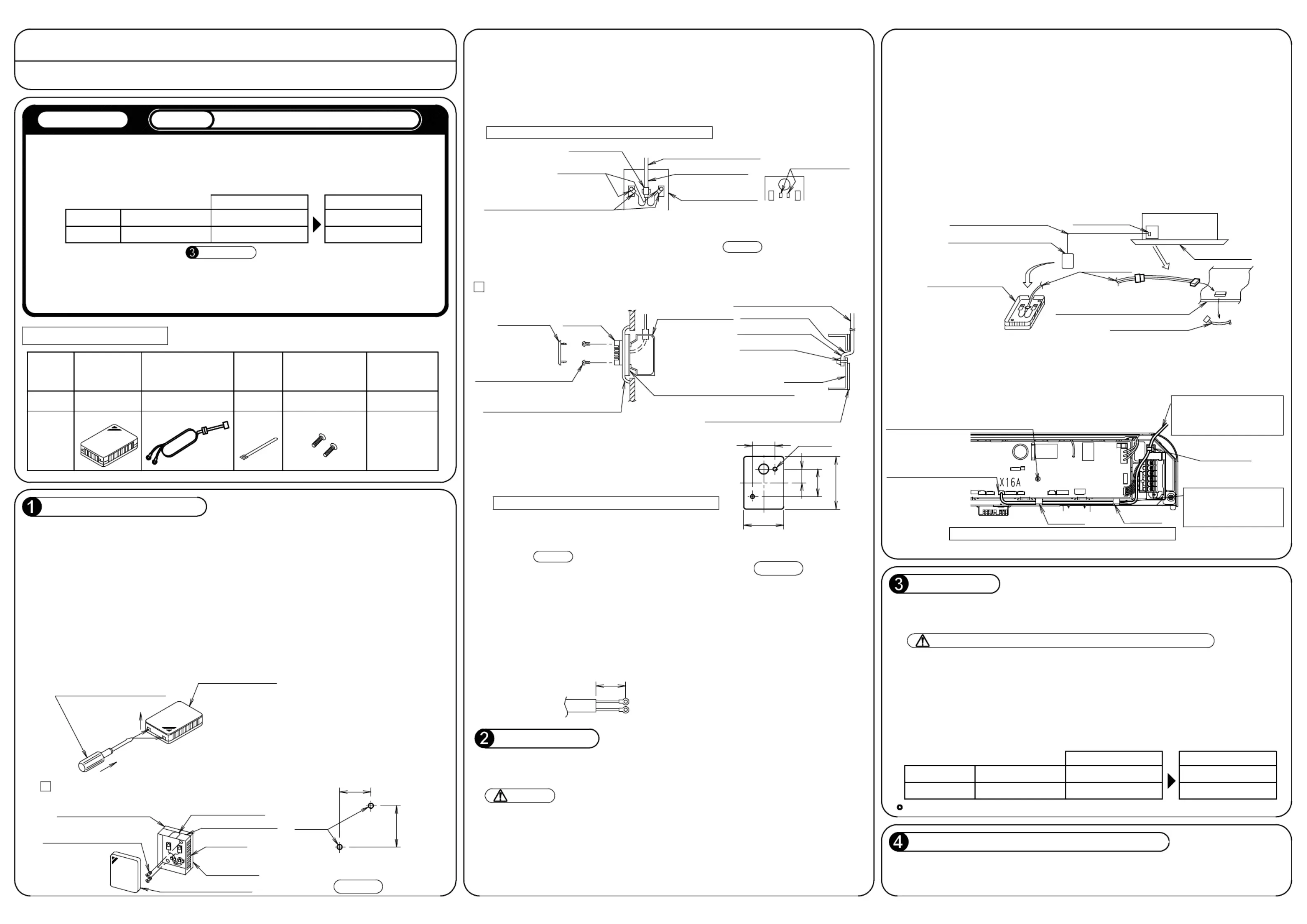
| Model: | KRCS01-5B |
Har du brug for hjælp?
Hvis du har brug for hjælp til Daikin KRCS01-5B stil et spørgsmål nedenfor, og andre brugere vil svare dig
Ikke kategoriseret Daikin Manualer
20 August 2025
20 August 2025

18 August 2025
17 August 2025
14 August 2025
13 August 2025

13 August 2025
12 August 2025
12 August 2025
12 August 2025
Ikke kategoriseret Manualer
- PowerXL
- Winia
- Mr Handsfree
- GoldenEar
- Lowepro
- Polaroid
- Ergotec
- Intel
- Unicol
- Minix
- Kino Flo
- Tzumi
- FANAUE
- Sanitec
- AudioQuest
Nyeste Ikke kategoriseret Manualer

7 December 2025

7 December 2025

7 December 2025

7 December 2025

7 December 2025

7 December 2025

7 December 2025

7 December 2025

7 December 2025

7 December 2025