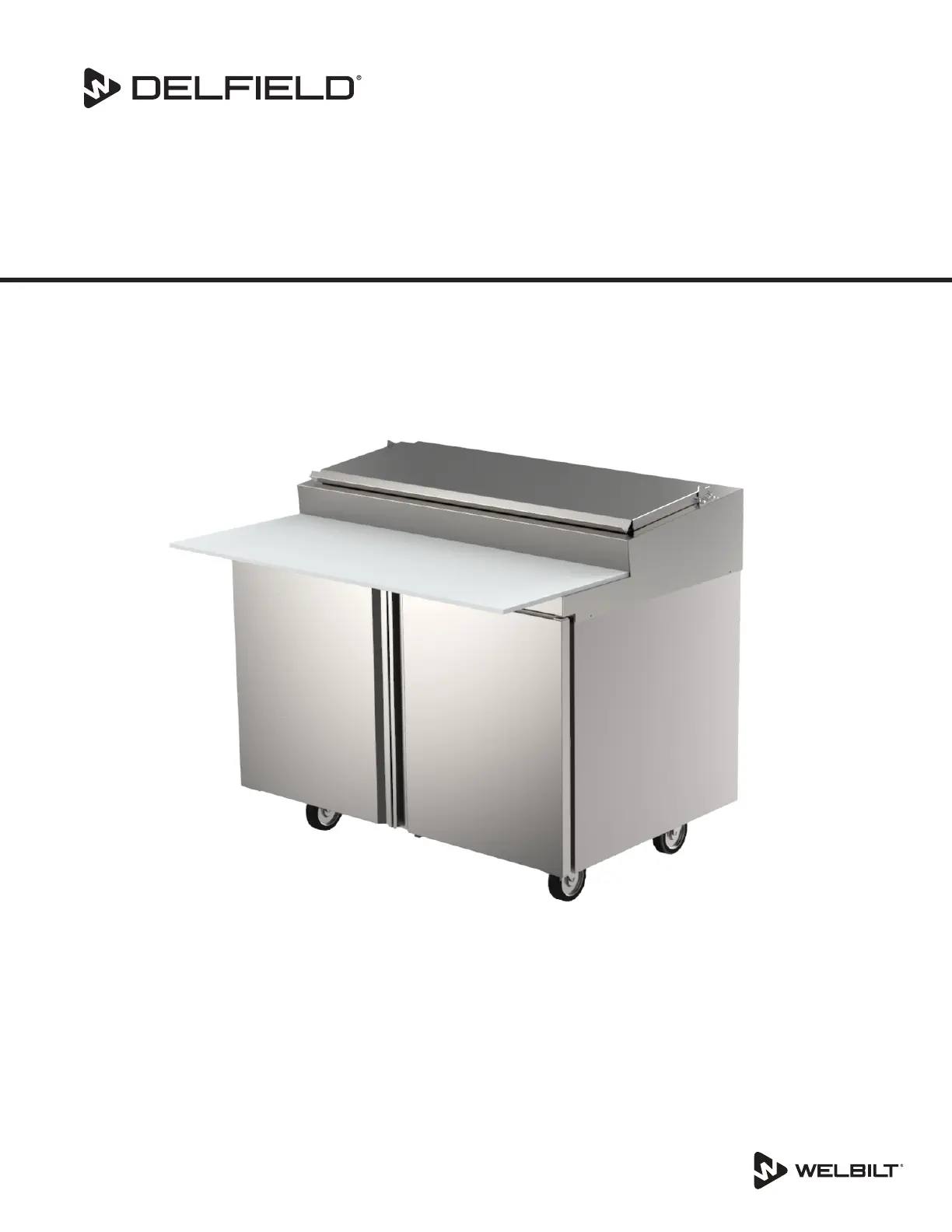
Delfield 4448NP Manual


Læs gratis den danske manual til Delfield 4448NP (28 sider) i kategorien Køleskab. Denne vejledning er vurderet som hjælpsom af 21 personer og har en gennemsnitlig bedømmelse på 4.4 stjerner ud af 11 anmeldelser. Har du et spørgsmål om Delfield 4448NP, eller vil du spørge andre brugere om produktet?

Side 1/28
Original Document
,
Caution
Read this instruction before operating this equipment.
Fresh Soluons, Fit For You
Part Number: 9295093A 02/21
Compact Refrigerators
4400 Series
Specifications, Installation, Operation & Maintenance Manual
This manual is updated as new information and models are released.
Visit our website for the latest information.
Safety Notices
n
Warning
Read this manual thoroughly before operating, installing
or performing maintenance on the equipment. Failure
to follow instructions in this manual can cause property
damage, injury or death.
DANGER
Do not install or operate equipment that has been misused,
abused, neglected, damaged, or altered/modified from
that of original manufactured specifications.
DANGER
Never stand on the unit! They are not designed to hold
the weight of an adult, and may collapse or tip if misused
in this manner.
DANGER
Keep power cord AWAY from HEATED surfaces. DO NOT
immerse power cord or plug in water. DO NOT let power
cord hang over edge of table or counter.
DANGER
All utility connections and fixtures must be maintained in
accordance with local and national codes.
n
Warning
Authorized Service Representatives are obligated to follow
industry standard safety procedures, including, but not
limited to, local/national regulations for disconnection
/ lock out / tag out procedures for all utilities including
electric, gas, water and steam.
n
Warning
Do not store or use gasoline or other flammable vapors
or liquids in the vicinity of this or any other appliance.
Never use flammable oil soaked cloths or combustible
cleaning solutions, for cleaning.
n
Warning
This product contains chemicals known to the State of
California to cause cancer and/or birth defects or other
reproductive harm. Operation, installation, and servicing
of this product could expose you to airborne particles
of glasswool or ceramic fibers, crystalline silica, and/
or carbon monoxide. Inhalation of airborne particles
of glasswool or ceramic fibers is known to the State of
California to cause cancer. Inhalation of carbon monoxide
is known to the State of California to cause birth defects
or other reproductive harm.
n
Warning
Do not use electrical appliances inside the food storage
compartments of the appliance, unless they are of the
type recommended by the manufacturer.
n
Warning
Use caution when handling metal surface edges of all
equipment.
n
Warning
This appliance is not intended for use by persons
(including children) with reduced physical, sensory or
mental capabilities, or lack of experience and knowledge,
unless they have been given supervision concerning use
of the appliance by a person responsible for their safety.
Do not allow children to play with this appliance.
Notice
Proper installation, care and maintenance are essential
for maximum performance and trouble-free operation of
your equipment. Visit our website www.wbtkitchencare.
com for manual updates, translations, or contact
information for service agents in your area.
Notice
This product utilizes Ecomate blowing agent methyl
formate
Part Number: 9295093A 02/21 3
Section 1
General Information
Serial Number Information ................................................................................................ 4
Warranty Information........................................................................................................ 4
Regulatory Certifications ................................................................................................... 4
Model Numbers ................................................................................................................ 4
Section 2
Installation
Location ............................................................................................................................ 6
Weight of Equipment ......................................................................................................... 7
Clearance Requirements .................................................................................................... 8
Dimensions ....................................................................................................................... 8
Capacity ............................................................................................................................ 9
Electrical Service ............................................................................................................. 10
Ground Fault Circuit Interrupter ...................................................................................10
Rated Amperages, Horsepower, Voltage & Power Cord Chart ......................................10
Drain Connections ........................................................................................................... 11
Refrigeration ................................................................................................................... 12
Level & Stable ................................................................................................................. 13
Leg & Caster Installation .................................................................................................. 13
Changing Pan Height ....................................................................................................... 13
Shelf Installation Instructions .......................................................................................... 13
Optional Overshelf Installation Instructions ..................................................................... 14
Heavy Duty Cutting Board Bracket Mounting ................................................................... 15
Section 3
Operation
Power To Cool ................................................................................................................. 19
Temperature Control ....................................................................................................... 19
Efficient Operation .......................................................................................................... 19
Defrost ............................................................................................................................ 19
Evaporator Fan Operation ................................................................................................ 19
Section 4
Maintenance
Interior Cleaning .............................................................................................................. 21
Gaskets .......................................................................................................................... 21
Preventing Blower Coil Corrosion .................................................................................22
Exterior Cleaning ............................................................................................................. 22
Drawer Assembly Cleaning .............................................................................................. 22
Quarterly Cleaning .......................................................................................................... 23
Interior Drain Lines ........................................................................................................23
Exterior Drain Lines ....................................................................................................... 23
Cleaning the Condenser Coil ............................................................................................ 24
Doors/Hinges .................................................................................................................. 24
Section 5
Wiring Diagrams
Wiring Diagram ............................................................................................................... 26
Table of Contents
4 Part Number: 9295093A 02/21
Serial Number Information
The serial number is on the identification plate that also
includes the model number. The identification plate is
located near the top front corner of the left interior wall.
Always have the serial number of your unit available
when calling for parts or service.
Warranty Information
Visit www.delfield.com/warranty to:
Register your product for warranty.
Verify warranty information.
View and download a copy of your warranty.
Regulatory Certifications
All models are certified by:
National Sanitation Foundation (NSF)
Underwriters Laboratories (UL)
Underwriters Laboratories of Canada (cUL)
Section 1
General Information
Model Numbers
This manual covers the following models:
Model Description
Refrigerated Front Breathers With Doors
4427NP-6
One Door Salad Top
4427NP-8
4427NP-9M
One Door Mega Top4427NP-12M
4432NP-12M
4448NP-6
Two Door Salad Top4448NP-8
4448NP-12
4448NP-6M
Two Door Mega Top4448NP-12M
4448NP-18M
4460NP-8
Two Door Salad Top
4460NP-12
4460NP-12M
Two Door Mega Top4460NP-18M
4460NP-24M
4464NP-8
Two Door Salad Top
4464NP-12
4464NP-12M Two Door Mega Top
4464NP-16 Two Door Salad Top
4464NP-18M
Two Door Mega Top
4464NP-24M
4472NP-12
Three Door Salad Top
4472NP-18
4472NP-18M
Three Door Mega Top4472NP-24M
4472NP-30M
Refrigerated Front Breathers With Drawers
D4427NP-6
Two Drawer Salad Top
D4427NP-8
D4427NP-9M
Two Drawer Mega TopD4427NP-12M
D4432NP-12M
D4448NP-6
Four Drawer Salad TopD4448NP-8
D4448NP-12
D4448NP-6M
Four Drawer Mega TopD4448NP-12M
D4448NP-18M
D4460NP-8
Four Drawer Salad Top
D4460NP-12
D4460NP-12M
Four Drawer Mega TopD4460NP-18M
D4460NP-24M
D4464NP-8
Four Drawer Salad Top
D4464NP-12
D4464NP-12M Four Drawer Mega Top
D4464NP-16 Four Drawer Salad Top
Part Number: 9295093 02/21 5
Section 1 General Information
Model Description
D4464NP-18M
Four Drawer Mega Top
D4464NP-24M
D4472NP-12
Six Drawer Salad Top
D4472NP-18
D4472NP-18M
Six Drawer Mega TopD4472NP-24M
D4472NP-30M
Refrigerated Front Breathers With Doors & 4” S/S Backsplash
ST4427NP-6
One Door Salad Top
ST4427NP-8
ST4448NP-6
Two Door Salad Top
ST4448NP-8
ST4460NP-8
ST4460NP-12
ST4448NP-6M
Two Door Mega Top
ST4448NP-12M
ST4460NP-12M
ST4460NP-18M
ST4464NP-8
Two Door Salad Top
ST4464NP-12
ST4464NP-12M
Two Door Mega Top
ST4464NP-18M
ST4472NP-12 Three Door Salad Top
ST4472NP-18M
Three Door Mega Top
ST4472NP-24M
Refrigerated Front Breathers w/ Drawers & 4” S/S Backsplash
STD4427NP-8 Two Drawer Salad Top
STD4448NP-6
Four Drawer Salad Top
STD4448NP-8
STD4460NP-8
STD4460NP-12
STD4448NP-6M
Four Drawer Mega Top
STD4448NP-12M
STD4460NP-12M
STD4460NP-18M
STD4464NP-8
Four Drawer Salad Top
STD4464NP-12
STD4464NP-12M
Four Drawer Mega Top
STD4464NP-18M
STD4472NP-12 Six Drawer Salad Top
STD4472NP-18M
Six Drawer Mega Top
STD4472NP-24M
Refrigerated Front Breathers w/ Doors & Raised Rail Prep Table
4448RP Two Section with six 1/3 pan capacity
4472RP Two Section with nine 1/3 pan capacity
4496RP Three Section with twelve 1/3 pan capacity
Refrigerated Front Breathers w/ Drawers & Raised Rail Prep Table
D4448RP Two Section with six 1/3 pan capacity
D4472RP Two Section with nine 1/3 pan capacity
D4496RP Three Section with twelve 1/3 pan capacity
6 Part Number: 9295093A 02/21
DANGER
Installation must comply with all applicable fire and
health codes in your jurisdiction.
DANGER
Use appropriate safety equipment during installation and
servicing.
n
Warning
Do not damage the refrigeration circuit when installing,
maintaining or servicing the unit.
Location
n
Warning
This equipment must be positioned so that the plug is
accessible unless other means for disconnection from the
power supply (e.g., circuit breaker or disconnect switch)
is provided.
n
Warning
Adequate means must be provided to limit the movement
of this appliance without depending on or transmitting
stress to the electrical conduit or gas lines.
n
Warning
To avoid instability the installation area must be capable
of supporting the combined weight of the equipment
and product. Additionally the equipment must be level
side to side and front to back.
n
Warning
This equipment is intended for indoor use only. Do not
install or operate this equipment in outdoor areas.
The location selected for the equipment must meet the
following criteria. If any of these criteria are not met, select
another location.
Units are intended for indoor use only.
The location MUST be level, stable and capable of
supporting the weight of the equipment.
The location MUST be free from and clear of combustible
materials.
Equipment MUST be level both front to back and side to
side.
Position the equipment so it will not tip or slide.
Front casters MUST be locked once positioned.
Recommended air temperature is 50° - 100°F
(10° - 38°C).
Proper air supply for ventilation is REQUIRED AND
CRITICAL for safe and efficient operation.
Do not obstruct the flow of ventilation air. Make sure the
air vents of the equipment are not blocked.
Do not install the equipment directly over a drain. Steam
rising up out of the drain will adversely affect operation,
air circulation, and damage electrical / electronic
components.
Section 2
Installation
Part Number: 9295093A 02/21 7
Section 2 Installation
Weight of Equipment
Model Ship Weight
Refrigerated Front Breathers With Doors
4427NP-6 223lbs (101kg)
4427NP-8 240lbs (109kg)
4427NP-9M
223lbs (101kg)
4427NP-12M
4432NP-12M 245lbs (111kg)
4448NP-6
316lbs (143kg)
4448NP-8
4448NP-12
4448NP-18M
4460NP-8
411lbs (186kg)
4460NP-12
4460NP-12M
4460NP-18M
4460NP-24M
4464NP-8
421lbs (191kg)
4464NP-12
4464NP-12M
4464NP-16
4464NP-18M
4464NP-24M
4472NP-12
461lbs (209kg)
4472NP-18
4472NP-18M
4472NP-24M
4472NP-30M
Refrigerated Front Breathers With Drawers
D4427NP-6 245lbs (111kg)
D4427NP-8 240lbs (109kg)
D4427NP-9M 245lbs (111kg)
D4427NP-12M 245lbs (111kg)
D4432NP-12M 293lbs (133kg)
D4448NP-8
398lbs (181kg)D4448NP-12
D4448NP-18M
D4460NP-8
495lbs (225kg)
D4460NP-12
D4460NP-12M
D4460NP-18M
D4460NP-24M
D4464NP-8
522lbs (237kg)
D4464NP-12
D4464NP-12M
D4464NP-16
D4464NP-18M
D4464NP-24M
D4472NP-12
545lbs (247kg)
D4472NP-18
D4472NP-18M
D4472NP-24M
D4472NP-30M
Model Ship Weight
Refrigerated Front Breathers With Doors & 4” S/S Backsplash
ST4427NP-6
240lbs (109kg)
ST4427NP-8
ST4448NP-6
316lbs (143kg)
ST4448NP-8
ST4460NP-8
411lbs (186kg)
ST4460NP-12
ST4460NP-12M
ST4460NP-18M
ST4464NP-8
421lbs (191kg)
ST4464NP-12
ST4464NP-12M
ST4464NP-18M
ST4472NP-12
461lbs (209kg)ST4472NP-18M
ST4472NP-24M
Refrigerated Front Breathers With Drawers & 4” S/S Backsplash
STD4427NP-6
240lbs (109kg)
STD4427NP-8
STD4448NP-6
398lbs (181kg)
STD4448NP-8
STD4460NP-8
495lbs (225kg)
STD4460NP-12
STD4460NP-12M
STD4460NP-18M
STD4464NP-8
522lbs (237kg)
STD4464NP-12
STD4464NP-12M
STD4464NP-18M
STD4472NP-12
545lbs (247kg)STD4472NP-18M
STD4472NP-24M
Refrigerated Front Breathers w/ Doors & Raised Rail Prep Table
4448RP 316lbs (143kg)
4472RP 461lbs (209kg)
4496RP ≈600lbs (272kg)
Refrigerated Front Breathers w/ Drawers & Raised Rail Prep Table
D4448RP 316lbs (143kg)
D4472RP 461lbs (209kg)
D4496RP ≈600lbs (272kg)
8 Part Number: 9295093A 02/21
Installation Section 2
Clearance Requirements
Keep the vents clean and free of obstruction.
Casters or optional legs must be used and not removed.
Provide good air circulation inside and outside the
cabinet.
Do not pack refrigerator so full that air cannot circulate.
Avoid hot corners and locations near stoves and ovens.
These cabinets have Delfield’s “front-breathing” design.
They may be installed flush against a wall or built into a
counter as required.
,
Caution
Any restriction of the proper air flow outlined above,
total or partial, will void the warranty on the cabinet.
Dimensions
Model Length Depth Work Height
Refrigerated Front Breathers With Doors
4427NP-6
27” (69cm) 31.50” (80cm) 36.00” (91cm)
4427NP-8
4427NP-9M
4427NP-12M
4432NP-12M 32” (81cm) 31.50” (80cm) 36.00” (91cm)
4448NP-6
48” (122cm) 31.50” (80cm) 36.00” (91cm)
4448NP-8
4448NP-12
4448NP-18M
4460NP-8
60” (152cm) 31.50” (80cm) 36.00” (91cm)
4460NP-12
4460NP-12M
4460NP-18M
4460NP-24M
4464NP-8
64” (163cm) 31.50” (80cm) 36.00” (91cm)
4464NP-12
4464NP-12M
4464NP-16
4464NP-18M
4464NP-24M
4472NP-12
72” (183cm) 31.50” (80cm) 36.00” (91cm)
4472NP-18
4472NP-18M
4472NP-24M
4472NP-30M
Refrigerated Front Breathers With Drawers
D4427NP-6
27” (69cm) 31.50” (80cm) 36.00” (91cm)
D4427NP-8
D4427NP-9M
D4427NP-12M
D4432NP-12M 32” (81cm) 31.50” (80cm) 36.00” (91cm)
D4448NP-6
48” (122cm) 31.50” (80cm) 36.00” (91cm)
D4448NP-8
D4448NP-12
D4448N-18M
Model Length Depth Work Height
D4460N-8
60” (152cm) 31.50” (80cm) 36.00” (91cm)
D4460NP-12
D4460NP-12M
D4460NP-18M
D4460NP-24M
D4464NP-8
64” (163cm) 31.50” (80cm) 36.00” (91cm)
D4464NP-12
D4464NP-12M
D4464NP-16
D4464NP-18M
D4464NP-24M
D4472NP-12
72” (183cm) 31.50” (80cm) 36.00” (91cm)
D4472NP-18
D4472NP-18M
D4472NP-24M
D4472NP-30M
Refrigerated Front Breathers With Doors & 4” S/S Backsplash
ST4427NP-6
27” (69cm) 31.50” (80cm) 36.00” (91cm)
ST4427NP-8
ST4448NP-6
48” (122cm) 31.50” (80cm) 36.00” (91cm)
ST4448NP-8
ST4460NP-8
60” (152cm) 31.50” (80cm) 36.00” (91cm)
ST4460NP-12
ST4460NP-12M
ST4460NP-18M
ST4464NP-8
64” (163cm) 31.50” (80cm) 36.00” (91cm)
ST4464NP-12
ST4464NP-12M
ST4464NP-18M
ST4472NP-12
72” (183cm) 31.50” (80cm) 36.00” (91cm)ST4472NP-18M
ST4472NP-24M
Refrigerated Front Breathers With Drawers & 4” S/S Backsplash
STD4427NP-6
27” (69cm) 31.50” (80cm) 36.00” (91cm)
STD4427NP-8
STD4448NP-6
48” (122cm) 31.50” (80cm) 36.00” (91cm)
STD4448NP-8
STD4460NP-8
60” (152cm) 31.50” (80cm) 36.00” (91cm)
STD4460NP-12
STD4460NP-12M
STD4460NP-18M
STD4464NP-8
64” (163cm) 31.50” (80cm) 36.00” (91cm)
STD4464NP-12
STD4464NP-12M
STD4464NP-18M
STD4472NP-12
72” (183cm) 31.50” (80cm) 36.00” (91cm)STD4472NP-18M
STD4472NP-24M
Part Number: 9295093A 02/21 9
Section 2 Installation
Refrigerated Front Breathers w/ Doors & Raised Rail Prep Table
4448RP 48” (122cm) 31.50” (80cm) 36.00” (91cm)
4472RP 72” (182cm) 31.50” (80cm) 36.00” (91cm)
4496RP 96” (244cm) 31.50” (80cm) 36.00” (91cm)
Refrigerated Front Breathers w/ Drawers & Raised Rail Prep Table
D4448RP 48” (122cm) 31.50” (80cm) 36.00” (91cm)
D4472RP 72” (182cm) 31.50” (80cm) 36.00” (91cm)
D4496RP 96” (244cm) 31.50” (80cm) 36.00” (91cm)
Capacity
Model
1/6 Pan
Capacity
Shelf Area Base Volume
Refrigerated Front Breathers With Doors
4427NP-6 6
3.17ft2 (2945cm2) 8.20ft3 (232L)4427NP-8 8
4427NP-9M 9
4432NP-12M 12 3.88ft2 (3605cm2) 10.10ft3 (286L)
4448NP-6 6
5.48ft2 (5091cm2) 16.00ft3 (453L)
4448NP-8 8
4448NP-12 12
4448NP-18M 18
4460NP-8 8
7.19ft2 (6680cm2) 20.20ft3 (572L)
4460NP-12 12
4460NP-12M 12
4460NP-18M 18
4460NP-24M 24
4464NP-8 8
7.76ft2 (7209cm) 21.60ft3 (612L)
4464NP-12 12
4464NP-12M 12
4464NP-16 16
4464NP-18M 18
4464NP-24M 24
4472NP-12 12
8.22ft2 (7637cm2) 24.80ft3 (702L)
4472NP-18 18
4472NP-18M 18
4472NP-24M 24
4472NP-30M 30
Refrigerated Front Breathers With Drawers
D4427NP-6 6
NA 8.20ft3 (232L)
D4427NP-8 8
D4427NP-9M 9
D4427NP-12M 12
D4432NP-12M 12 NA 10.10ft3 (286L)
D4448NP-6 6
NA 16.00ft3 (453L)
D4448NP-8 8
D4448NP-12 12
D4448NP-18M 18
D4460NP-8 8
NA 20.20ft3 (572L)
D4460NP-12 12
D4460NP-12M 12
D4460NP-18M 18
D4460NP-24M 24
D4464NP-8 8
NA 21.60ft3 (612L)
D4464NP-12 12
D4464NP-12M 12
D4464NP-16 16
D4464NP-18M 18
D4464NP-24M 24
Model
1/6 Pan
Capacity
Shelf Area Base Volume
D4472NP-12 12
NA 24.80ft3 (702L)
D4472NP-18 18
D4472NP-18M 18
D4472NP-24M 24
D4472NP-30M 30
Refrigerated Front Breathers With Doors & 4” S/S Backsplash
ST4427NP-6 6
3.17ft2 (2945cm2) 8.20ft3 (232L)
ST4427NP-8 8
ST4448NP-6 6
5.48ft2 (5091cm2) 16.00ft3 (453L)
ST4448NP-8 8
ST4460NP-8 8
7.19ft2 (6680cm2) 20.20ft3 (572L)
ST4460NP-12 12
ST4460NP-12M 12
ST4460NP-18M 18
ST4464NP-8 8
7.76ft2 (7209cm) 21.60ft3 (612L)
ST4464NP-12 12
ST4464NP-12M 12
ST4464NP-18M 18
ST4472NP-12 12
8.22ft2 (7637cm2) 24.80ft3 (702L)ST4472NP-18M 18
ST4472NP-24M 24
Refrigerated Front Breathers With Drawers & 4” S/S Backsplash
STD4427NP-6 6
NA 8.20ft3 (232L)
STD4427NP-8 8
STD4448NP-6 6
NA 16.00ft3 (453L)
STD4448NP-8 8
STD4460NP-8 8
NA 20.20ft3 (572L)
STD4460NP-12 12
STD4460NP-12M 12
STD4460NP-18M 18
STD4464NP-8 8
NA 21.60ft3 (612L)
STD4464NP-12 12
STD4464NP-12M 12
STD4464NP-18M 18
STD4472NP-12 12
NA 24.80ft3 (702L)STD4472NP-18M 18
STD4472NP-24M 24
Refrigerated Front Breathers w/ Doors & Raised Rail Prep Table
4448RP 6 5.48ft2 (5091cm2) 17.96ft3 (509L)
4472RP 9 8.22ft2 (7637cm2) 27.80ft3 (787L)
4496RP 12 11.64ft2
(10814cm2)
37.65ft3 (1066L)
Refrigerated Front Breathers w/ Drawers & Raised Rail Prep Table
D4448RP 6 N/A 17.96ft3 (509L)
D4472RP 9 N/A 27.80ft3 (787L)
D4496RP 12 N/A 37.65ft3 (1066L)
10 Part Number: 9295093A 02/21
Installation Section 2
Electrical Service
DANGER
Check all wiring connections, including factory terminals,
before operation. Connections can become loose during
shipment and installation.
n
Warning
This appliance must be grounded and all field wiring must
conform to all applicable local and national codes. Refer
to rating plate for proper voltage. It is the responsibility of
the end user to provide the disconnect means to satisfy
the authority having jurisdiction.
The Danfoss control can be used to power down and shut
off the unit.
All electrical work, including wire routing and grounding,
must conform to local, state and national electrical codes.
The equipment must be grounded.
A separate fuse/circuit breaker must be provided for each
unit.
The maximum allowable voltage variation is ±10% of the
rated voltage at equipment start-up (when the electrical
load is highest).
Check all green ground screws, cables and wire
connections to verify they are tight before start-up.
GROUND FAULT CIRCUIT INTERRUPTER
Ground Fault Circuit Interrupter (GFCI/GFI) protection is a
system that shuts down the electric circuit (opens it) when it
senses an unexpected loss of power, presumably to ground.
Welbilt does not recommend the use of GFCI/GFI circuit
protection to energize our equipment. If code requires the
use of a GFCI/GFI then you must follow the local code. The
circuit must be dedicated, sized properly and there must
be a panel GFCI/GFI breaker. We do not recommend the
use of GFCI/GFI outlets to energize our equipment as they
are known for more intermittent nuisance trips than panel
breakers.
RATED AMPERAGES, HORSEPOWER, VOLTAGE & POWER
CORD CHART
Maximum 6ft (1.8m) cord with three-pronged plug. Plug
into a three-pronged wall outlet for proper grounding of the
cabinet to begin operation. Do not use an adapter to connect
to a two-pronged outlet.
Model Amp H.P.
Voltage, Cycle,
Phase
NEMA
Plug
Refrigerated Front Breathers With Doors
4427NP-6
4 .3 115, 60, 1 5-15P
4427NP-8
4427NP-9M
4427NP-12M
4432NP-12M 4 .3 115, 60, 1 5-15P
4448NP-6
4 .3 115, 60, 1 5-15P
4448NP-8
4448NP-12
4448NP-18M
4460NP-8
6 .35 115, 60, 1 5-15P
4460NP-12
4460NP-12M
4460NP-18M
4460NP-24M
4464NP-8
6 .35 115, 60, 1 5-15P
4464NP-12
4464NP-12M
4464NP-16
4464NP-18M
4464NP-24M
4472NP-12
6 .35 115, 60, 1 5-15P
4472NP-18
4472NP-18M
4472NP-24M
4472NP-30M
Refrigerated Front Breathers With Drawers
D4427NP-6
4 .3 115, 60, 1 5-15P
D4427NP-8
D4427NP-9M
D4427NP-12M
D4432NP-12M 4 .3 115, 60, 1 5-15P
D4448NP-6
4 .3 115, 60, 1 5-15P
D4448NP-8
D4448NP-12
D4448NP-18M
D4460NP-8
6 .35 115, 60, 1 5-15P
D4460NP-12
D4460NP-12M
D4460NP-18M
D4460NP-24M
D4464NP-8
6 .35 115, 60, 1 5-15P
D4464NP-12
D4464NP-12M
D4464NP-16
D4464NP-18M
D4464NP-24M
Part Number: 9295093A 02/21 11
Section 2 Installation
Model Amp H.P.
Voltage, Cycle,
Phase
NEMA
Plug
D4472NP-12
6 .35 115, 60, 1 5-15P
D4472NP-18
D4472NP-18M
D4472NP-24M
D4472NP-30M
Refrigerated Front Breathers With Doors & 4” S/S Backsplash
ST4427NP-6
4 .3 115, 60, 1 5-15P
ST4427NP-8
ST4448NP-6
4 .3 115, 60, 1 5-15P
ST4448NP-8
ST4460NP-8
6 .35 115, 60, 1 5-15P
ST4460NP-12
ST4460NP-12M
ST4460NP-18M
ST4464NP-8
6 .35 115, 60, 1 5-15P
ST4464NP-12
ST4464NP-12M
ST4464NP-18M
ST4472NP-12
6 .35 115, 60, 1 5-15PST4472NP-18M
ST4472NP-24M
Refrigerated Front Breathers With Drawers & 4” S/S Backsplash
STD4427NP-6
4 .3 115, 60, 1 5-15P
STD4427NP-8
STD4448NP-6
4 .3 115, 60, 1 5-15P
STD4448NP-8
STD4460NP-8
6 .35 115, 60, 1 5-15PSTD4460NP-12M
STD4460NP-18M
STD4464NP-8
6 .35 115, 60, 1 5-15P
STD4464NP-12
STD4464NP-12M
STD4464NP-18M
STD4472NP-12
6 .35 115, 60, 1 5-15PSTD4472NP-18M
STD4472NP-24M
Refrigerated Front Breathers w/ Doors & Raised Rail Prep Table
4448RP 4.0 .3 115, 60, 1 5-15P
4472RP 6.0 .35 115, 60, 1 5-15P
4496RP 6.0 .35 115, 60, 1 5-15P
Refrigerated Front Breathers w/ Drawers & Raised Rail Prep Table
D4448RP 4.0 .3 115, 60, 1 5-15P
D4472RP 6.0 .35 115, 60, 1 5-15P
D4496RP 6.0 .35 115, 60, 1 5-15P
Drain Connections
n
Warning
Moisture collecting from improper drainage can create a
slippery surface on the floor and a hazard to employees.
It is the owners responsibility to provide a container or
outlet for drainage.
Self-contained models are standard with a condensate
evaporator. If, for some reason, a cabinet does not have a
condensate evaporator, or the evaporator fails, the cabinets
drain must have an outlet to an appropriate drainage area or
container.
12 Part Number: 9295093A 02/21
Installation Section 2
Refrigeration
Model BTU/Hour
Capacity
Heat of
Rejection
R290 Charge
Refrigerated Front Breathers With Doors
4427NP-6
2038 716 60g
4427NP-8
4427NP-9M
4427NP-12M
4432NP-12M 2038 883 60g
4448NP-6
2038 1299 60g
4448NP-8
4448NP-12
4448NP-18M
4460NP-8
2973 1645 72g
4460NP-12
4460NP-12M
4460NP-18M
4460NP-24M
4464NP-8
2973 1664 72g
4464NP-12
4464NP-12M
4464NP-16
4464NP-18M
4464NP-24M
4472NP-12
2973 2042 72g
4472NP-18
4472NP-18M
4472NP-24M
4472NP-30M
Refrigerated Front Breathers With Drawers
D4427NP-6
2038 716 60g
D4427NP-8
D4427NP-9M
D4427NP-12M
D4432NP-12M 2038 883 60g
D4448NP-6
2038 1299 60g
D4448NP-8
D4448NP-12
D4448NP-18M
D4460NP-8
2973 1645 72g
D4460NP-12
D4460NP-12M
D4460NP-18M
D4460NP-24M
D4464NP-8
2973 1664 72g
D4464NP-12
D4464NP-12M
D4464NP-16
D4464NP-18M
D4464NP-24M
D4472NP-12
2973 2042 72g
D4472NP-18
D4472NP-18M
D4472NP-24M
D4472NP-30M
Model BTU/Hour
Capacity
Heat of
Rejection
R290 Charge
Refrigerated Front Breathers With Doors & 4” S/S Backsplash
ST4427NP-6
2038 716 60g
ST4427NP-8
ST4448NP-6
2038 1299 60g
ST4448NP-8
ST4460NP-8
2973 1645 72g
ST4460NP-12
ST4460NP-12M
ST4460NP-18M
ST4464NP-8
2973 1664 72g
ST4464NP-12
ST4464NP-12M
ST4464NP-18M
ST4472NP-12
2973 2042 72gST4472NP-18M
ST4472NP-24M
Refrigerated Front Breathers With Drawers & 4” S/S Backsplash
STD4427NP-6
2038 716 60g
STD4427NP-8
STD4448NP-6
2038 1299 60g
STD4448NP-8
STD4460NP-8
2973 1645 72g
STD4460NP-12
STD4460NP-12M
STD4460NP-18M
STD4464NP-8
2973 1664 72g
STD4464NP-12
STD4464NP-12M
STD4464NP-18M
STD4472NP-12
2973 2042 72gSTD4472NP-18M
STD4472NP-24M
Refrigerated Front Breathers w/ Doors & Raised Rail Prep Table
4448RP 1756 1084 60g
4472RP 2899 1636 72g
4496RP 2899 2093 72g
Refrigerated Front Breathers w/ Drawers & Raised Rail Prep Table
D4448RP 1756 1084 60g
D4472RP 2899 1636 72g
D4496RP 2899 2093 72g
Part Number: 9295093A 02/21 13
Section 2 Installation
Level & Stable
After the cabinet has been placed in the desired location,
cabinets with legs must be leveled. Level units from front to
back and from side to side. Leveling will insure proper door
operation and removal of condensate. It is very important
that all legs are properly adjusted to keep the cabinet level,
evenly distribute the weight and to make sure the unit will
not rock, lean or be unstable.
Cabinets with casters must have the caster brake set so the
cabinet cannot move.
Leg & Caster Installation
DANGER
Legs or casters must be installed and the legs or casters
must be screwed in completely to prevent bending. When
casters are installed the mass of this unit will allow it to
move uncontrolled on an inclined surface. These units
must be tethered/secured to comply with all applicable
codes.
n
Warning
The unit must be installed in a stable condition with
the front wheels locked. Locking the front casters after
installation is the owners and operators responsibility.
n
Warning
Use a jack to lift the refrigeration unit off the ground
just far enough to remove the leg/caster. Place blocking
underneath the unit. Do not work underneath a raised
unit without proper blocking. Do not lift the unit more
than necessary to remove the leg/caster. Lifting the unit
too far can make the unit unstable.
,
Caution
All single-section units require that the swivel casters be
mounted on the front and rigid casters be mounted on
the rear.
Changing Pan Height
If additional pan temperature cooling ability is desired,
especially in higher ambient temperature conditions and/
or if pan covers are open or off for extended time periods
improved cooling of pans can usually be achieved by utilizing
the lower position of the dual level pan guides.
When utilizing the lower position on a model with drawers,
only 4” deep pans can be used in the top. When utilizing the
lower position on a door model, 4” or 6” deep pans may be
used.
1. Remove all pans, pan dividers, front and rear support bars.
2. Remove the upper side support brackets by pulling them
up and off.
3. Reinstall all components removed in step one.
Use side support alone
to lower pans 1”
Remove upper side
support bracket
If the lower pan position is desired for models 4427N-8 or
4427N-12M, model specific brackets must be ordered. They
will replace all other brackets.
Shelf Installation Instructions
1. Notice the shelves have four alignment pins on the
underside and a backstop on the top back.
2. Insert the shelves into the cabinet.
The backstop should be at the top back.
Back of unit
The alignment pins should be in front and back of the
shelf supports.
14 Part Number: 9295093A 02/21
Installation Section 2
Optional Overshelf Installation Instructions
If the unit is ordered to have the overshelf:
1. Remove the three screws from each top side of the
cabinet (total six screws).
2. Set the overshelf in-place on the top of the cabinet.
3. Line up the overshelf holes with the unit holes.
4. Secure with three screws per side of the cabinet (total
six screws).
If the overshelf was not ordered with the unit:
1. Set the overshelf in-place on the top of the cabinet.
2. Secure with three screws per side of the cabinet (total
six screws).
Part Number: 9295093A 02/21 15
Section 2 Installation
Standard Heavy Duty Cutting Board Bracket
Mounting
Supplies Needed
#3 Phillips Screwdriver
Parts Included For 27” & 32” Units
Qty Description Part No.
1 Left Bracket Varies
1 Right Bracket Varies
2 Screw, pan head 9321519
2 Screw, flat head 9324092
2 Fender Washer 9324043
Parts Included For 48” Units
Qty Description Part No.
1 Left Bracket Varies
1 Center Bracket Varies
1 Right Bracket Varies
1 Silicone 9291311
3 Screw, pan head 9321519
3 Screw, flat head 9324092
3 Fender Washer 9324043
Parts Included For 60”, 64” & 72” Units
Qty Description Part No.
1 Left Bracket Varies
2 Center Bracket Varies
1 Right Bracket Varies
1 Silicone 9291311
4 Screw, pan head 9321519
4 Screw, flat head 9324092
4 Fender Washer 9324043
Left Bracket
Center Bracket
Right Bracket
16 Part Number: 9295093A 02/21
Installation Section 2
Heavy Duty Cutting Board Bracket Mounting Instructions
1. Attach each bracket to the top of the unit with one flat
head screw (9324092).
Top
2. Attach each bracket to the face of the unit with one
fender washer (9324043) and one pan head screw
(9321519).
Some adjustment to align the brackets may be
necessary once the cutting board is installed.
Do not over tighten the screws.
Face
3. Install the cutting board onto the brackets.
Make final bracket adjustments so the cutting board
sits flush in the brackets.
Tighten screws.
Part Number: 9295093A 02/21 17
Section 2 Installation
4427NP (R290) & 4427N (404) Lid installation
Secure The Fixed Cover To The Unit
Qty Part # Part Description
2 9321170 Screw, Thumb, #10-32x.50
2 MCP00207 Screw, Shoulder, S/S. 8-32 Epoxy
1. Attach the fixed cover to the rear of the unit with two
thumb screws.
2. Attach the fixed cover to the sides of the unit with two
shoulder screws.
3. Enlarge the fixed cover screw holes with a 3/16” drill bit.
Attache The Rolling Lid
NOTE: Complete these steps on both ends.
4427NP
Qty Part # Part Description
2 9321721 Standoff, Press, 6/32
2 9321722 Screw, #6-32 x .25” w/ Loctite
2 9325079 Spacer, Nylon, .125 Thk .252 ID, .50 OD
4427N
Qty Part # Part Description
2 9325077 Bolt, Barrel, 1/4
2 9325078 Screw, Machine, Truss Head, 10-24
2 9325079 Spacer, Nylon, .125 Thk .252 ID, .50 OD
2 9324042 Washer, 1/4, S/S, Flat
Plus a stainless
steel washer
4. Place the rolling lid inside the fixed cover.
5. Start from the outside.
6. Insert the screw through the fixed cover only.
7. Put a nylon spacer on the screw.
8. Insert the screw through the rolling lid.
Screw
Fixed Cover
Nylon Spacer
Rolling Lid
9. Secure the screw from the inside with a barrel bolt.
S/S Washer
18 Part Number: 9295093A 02/21
DANGER
The on-site supervisor is responsible for ensuring that
operators are made aware of the inherent dangers of
operating this equipment.
DANGER
Do not operate any appliance with a damaged cord or
plug. All repairs must be performed by a qualified service
company.
DANGER
Never stand on the unit! They are not designed to hold
the weight of an adult, and may collapse or tip if misused
in this manner.
n
Warning
Do not contact moving parts.
n
Warning
All covers and access panels must be in place and properly
secured, before operating this equipment.
n
Warning
The operator of this equipment is solely responsible
for ensuring safe holding temperature levels for all
food items. Failure to do so could result in unsafe food
products for customers.
n
Warning
Overloading shelves can damage equipment or cause
bodily injury.
n
Warning
Damp or wet hands may stick to cold surfaces.
n
Warning
Do not block the supply and return air grills or the air
space around the air grills. Keep plastic wrappings,
paper, labels, etc. from being airborne and lodging in
the grills. Failure to keep the air grills clear will result in
unsatisfactory operation of the system.
,
Caution
Do not throw items into the storage area. Failure to
heed this recommendation could result in damage to the
interior of the cabinet or to the blower coil.
Section 3
Operation
Part Number: 9295093A 02/21 19
Section 3 Operation
Power To Cool
After the cabinet is connected to the power source it will
automatically begin operating.
With the covers and doors closed, the temperature of the
cabinet should reach 36°F to 40°F (2°C to 4°C) in about
one hour.
Temperature on salad top will maintain 33°F to 41°F (1°C
to 4°C) with pans recessed 2.5” (6.5cm) at 86°F ambient
room temperature for a period of four hours, meeting
NSF-7 requirements.
Temperature Control
The temperature control on all sald top units is located in
the rear of the unit.
The factory setting for the control is 37.5°F and maintains
about 34°F(1°C) to 40°F (2°C) inside the box.
There is also an optional display that can be added to the
front nosing of the unit. The control (without display)
would be mounted on the back of the unitl with a cable
connecting to the display.
Temperature Control Error Codes
Sensor 1 defect E01 Air sensor
Sensor 2 defect E02 Coil sensor
High Temp Alarm Hi Automacally
switching at 2
second rate
Low Temp Alarm Lo
Line Voltage too
high
uHi
Ling voltage too
low
uLo
Control calls for
cooling for more
than 24 hours
straight
LEA Time includes
defrost. Error will
go away if the
control cycles o
the compressor
or if the power is
shut o.
Efficient Operation
Cabinets with pans should be operated with pans in
place. Operating the cabinet without all pans in place
may damage the cabinet.
Continuous opening and closing of the door will hamper
the cabinet’s ability to maintain optimum refrigeration
temperature.
Top section is not intended for overnight storage. Product
should be removed from pans. Pans can remain in
cabinet while empty.
Defrost
The electronic temperature controller monitors evaporator
temperature and compressor run time to determine the
proper time for a positive defrost cycle. A defrost cycle
can occur as often as every 45 minutes under extremely
heavy usage. When the controller enters the defrost mode
the compressor is shut off and will remain off until the
evaporator coil temperature exceeds 41°F or the controller
reaches a time limit of 50 minutes. The defrost cycle can last
from a minimum of 2 minutes to a maximum of 50 minutes.
Evaporator Fan Operation
Salad and mega top refrigerator units under 60” wide have
one evaporator and one axial fan. 60”, 64” and 72” wide units
have one large evaporator and two axial fans.
Cooling Cycle Defrost Cycle
Compressor On Compressor Off Compressor Off
Evaporator Fan Evaporator Fan Evaporator Fan
On On three minutes
the off three
minutes
On
During normal operation the evaporator fan may cycle
and/or pulse independently of the compressor. Consult
the service manual or contact Technical Support at
1-844-724-CARE if you are unsure of the proper
function.
20 Part Number: 9295093A 02/21
Operation Section 3
THIS PAGE INTENTIONALLY LEFT BLANK
Part Number: 9295093A 02/21 21
DANGER
It is the responsibility of the equipment owner to perform
a Personal Protective Equipment Hazard Assessment
to ensure adequate protection during maintenance
procedures.
DANGER
Failure to disconnect the power at the main power supply
disconnect could result in serious injury or death. The
power switch DOES NOT disconnect all incoming power.
DANGER
Disconnect electric power at the main power disconnect
for all equipment being serviced. Observe correct polarity
of incoming line voltage. Incorrect polarity can lead to
erratic operation.
n
Warning
Never use sharp objects or tools to remove ice or frost. Do
not use mechanical devices or other means to accelerate
the defrosting process.
n
Warning
When using cleaning fluids or chemicals, rubber gloves
and eye protection (and/or face shield) must be worn.
n
Warning
When cleaning interior and exterior of unit, care should
be taken to avoid the front power switch and the rear
power cord. Keep water and/or cleaning solutions away
from these parts.
n
Warning
Never use a high-pressure water jet for cleaning or hose
down or flood interior or exterior of units with water. Do
not use power cleaning equipment, steel wool, scrapers
or wire brushes on stainless steel or painted surfaces.
,
Caution
Maintenance and servicing work other than cleaning as
described in this manual must be done by an authorized
service personnel.
,
Caution
Over shelves and other items mounted to the top of the
counters should never be installed in the field due to the
potential damage to the refrigeration system.
Responsibility
You are responsible for maintaining the equipment
in accordance with the instructions in this manual.
Maintenance procedures are not covered by the warranty.
Maintenance Daily Weekly Quarterly After Prolonged Shutdown At Start-Up
Interior X X X
Gasket X X X
Exterior X X X
Drawer Track X X X
Drain X X X
Condenser Coil X X X
Hinge screws X X X
Casters X X X
Interior Cleaning
The interior can be cleaned using soap and warm water. If
this isn’t sufficient, try ammonia and water or a nonabrasive
liquid cleaner.
GASKETS
Gaskets require regular cleaning to prevent mold and mildew
build up and also to retain the elasticity of the gasket. Clean
them with water and mild soap (not citrus based). Avoid full
strength cleaning products on gaskets as this can cause them
to become brittle and crack. Never use sharp tools or knives
to scrape or clean the gasket. Gaskets can be easily replaced
Section 4
Maintenance
22 Part Number: 9295093A 02/21
Maintenance Section 4
and do not require the use of tools or an authorized service
person. The gaskets are dart style and can be pulled out of
the groove in the door. Place gasket in warm water to make
the material more pliable for installation. Dry and press into
place.
PREVENTING BLOWER COIL CORROSION
To help prevent corrosion of the blower coil, store all acidic
items, such as pickles and tomatoes, in seal-able containers.
Immediately wipe up all spills.
Exterior Cleaning
,
Caution
Never use an acid based cleaning solution on exterior
panels! Many food products have an acidic content,
which can deteriorate the finish. Be sure to clean ALL
food products from stainless steel surfaces.
Clean the area around the unit as often as necessary to
maintain cleanliness and efficient operation.
Wipe exterior surfaces with a damp cloth rinsed in water to
remove dust and dirt from the outside of the unit. Always
rub with the “grain” of the stainless steel to avoid marring
the finish. If a greasy residue persists, use a damp cloth
rinsed in a mild dish soap and water solution. Wipe dry with
a clean, soft cloth.
Never use steel wool or abrasive pads for cleaning. Never use
chlorinated, citrus based or abrasive cleaners.
Stainless steel exterior panels have a clear coating that
is stain resistant and easy to clean. Products containing
abrasives will damage the coating and scratch the panels.
Daily cleaning may be followed by an application of stainless
steel cleaner which will eliminate water spotting and
fingerprints. Early signs of stainless steel breakdown are
small pits and cracks. If this has begun, clean thoroughly and
start to apply stainless steel cleaners in attempt to restore
the steel.
Wipe casters with a damp cloth monthly to prevent
corrosion.
Drawer Assembly Cleaning
The drawer assembly is designed to be cleaned easily. Both
drawer and tracks are removable without tools. The drawer
tracks are dishwasher safe or can be cleaned in a sink with
detergents and a soft bristle brush. Drawers and tracks
should be cleaned on a weekly basis.
Remove Drawers
Pull the drawer box out until it stops. Lift up on the drawer
front and pull the drawer box completely out. Using a soft
bristle brush, clean the track on the bottom of the drawer
box. When finished, it should be wiped clean of all food and
debris.
Tracks
The drawer box
assembly must be
removed. Pull the
drawer tracks out
until they hit a stop.
Locate blue safety
clips towards the
back of each drawer track. Blue safety clips have a tab on
the top. Push the tab back until it clicks. Lift up and pull
the drawer tracks all the way out of the drawer cage. The
drawer tracks are dishwasher safe or can be cleaned in a sink
with detergents and a soft bristle brush. Drawers and tracks
should be cleaned on a weekly basis. Using a soft bristle
brush, wash the track making sure each roller is thoroughly
cleaned. The drawer cage should be cleaned with a soft
bristle brush, removing any food and debris gathered on the
bottom ledge. Once its cleaned thoroughly with a soft bristle
brush, wipe remaining debris clean with a soft towel.
Reassembly
Push the drawer tracks into the drawer cage. The blue safety
clip must remain pushed towards the back. Lift up and slide
the drawer track all the way into the drawer cage. The blue
safety clip will lock in place automatically. Once all tracks are
replaced, insert the drawer box. Rest the drawer box bottom
track on the front track roller. Then push the drawer back
in place SLOWLY. When the drawer box is about half way in
you will hit a STOP. You must lift the front of the drawer up
approximately ½” (1.3cm) to continue inward. Clean tracks as
often as possible. The cleaner the tracks are the better they
will operate.
tab on top of blue
safety clip
Part Number: 9295093A 02/21 23
Section 4 Maintenance
Quarterly Cleaning
If you notice water accumulation on the inside of the unit,
follow the instructions for cleaning the interior condensate
pan and exterior drain lines.
Note: This cleaning instruction applies to 4400 units produced
after July, 2020.
INTERIOR DRAIN LINES
The unit will have a drain located inside the unit that
removes the condensation from the evaporator coil and
routes it to an external condensate evaporator pan. The drain
pan and hose can be accessed through a louver on the
bottom interior of the cabinet as seen in following picture.
To clean the pan, remove the 5/16” screws from the
evaporator cover.
For larger units the center shelf racks do not need to be
removed. Using a soft bristle brush, like the ones in the
following pocture, clear the drain line and pan of any debris.
Be sure not to use sharp metal objects to clean stainless
surfaces, this may damage crucial protective surfaces.
Reinstall the evaporator cover and the 5/16” screws.
Continue to clean the drain lines from the exterior.
EXTERIOR DRAIN LINE
Each unit has a drain located behind the unit that removes
the condensation from the interior drain line tray into the
evaporator below the unit. Located behind the center panel
in the following image.
Behind this panel is a clear rubber hose inserted into a
copper 90° pipe, as shown below. This connection is behind
PermaGum, an insulator that must be preserved and
replaced after cleaning. Failure to properly replace the
PermaGum will result in a poorly functioning unit.
PermaGum
Pipe cleaning brushes can be found
locally near you.
24 Part Number: 9295093A 02/21
Maintenance Section 4
Remove the clear rubber hose and the copper 90° pipe and
inspect/clean any debris. After cleaning, be sure to reinstall
the pipe and hose and firmly pack the black PurmaGum
back into place to not allow warm air into the unit. Be sure
to replace the clear rubber hose back into the condensate
drain pan down below making sure the hose does not kink or
hold water. Reinstall the rear panel.
CLEANING THE CONDENSER COIL
In order to maintain proper refrigeration performance, the
condenser fins must be cleaned of dust, dirt and grease
regularly. It is recommended that this be done monthly. If
conditions are such that the condenser is totally blocked
in a month, the frequency of cleaning should be increased.
Clean the condenser with a vacuum cleaner or stiff brush. If
extremely dirty, a commercially available condenser cleaner
may be required.
Failure to maintain a clean condenser coil can initially cause
high temperatures and excessive run times. Continuous
operation with a dirty or clogged condenser coil can result in
compressor failure. Neglecting the condenser coil cleaning
procedures will void any warranties associated with the
compressor and cost to replace the compressor.
DOORS/HINGES
Over time and with heavy-use doors, the hinges may become
loose. If this happens, tighten the screws that mount the
hinge brackets to the frame of the unit. Loose or sagging
doors can cause the hinges to pull out of the frame, which
may damage both the doors and the hinges. In some cases
this may require qualified service agents or maintenance
personnel to perform repairs.
Hinge Screws
Copper 90° W/
Rubber hose
Part Number: 9295093A 02/21 25
Section 4 Maintenance
THIS PAGE INTENTIONALLY LEFT BLANK
26 Part Number: 9295093A 02/21
Section 5
Wiring Diagrams
Part Number: 9295093A 02/21 27
Section 5 Wiring Diagrams
THIS PAGE INTENTIONALLY LEFT BLANK
DELFIELD
980 SOUTH ISABELLA ROAD, MOUNT PLEASANT, MI 48858
800-733-8821
WWW.DELFIELD.COM
©2019 Welbilt Inc. except where explicitly stated otherwise. All rights reserved.
Part Number: 9295093A 02/21


Produkt Specifikationer

Mærke: Delfield
Kategori: Køleskab
Model: 4448NP

Har du brug for hjælp?

Hvis du har brug for hjælp til Delfield 4448NP stil et spørgsmål nedenfor, og andre brugere vil svare dig