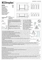
Dimplex 403TSTI Manual


Læs gratis den danske manual til Dimplex 403TSTI (4 sider) i kategorien Varmeapparat. Denne vejledning er vurderet som hjælpsom af 50 personer og har en gennemsnitlig bedømmelse på 4.6 stjerner ud af 25.5 anmeldelser. Har du et spørgsmål om Dimplex 403TSTI, eller vil du spørge andre brugere om produktet?

Side 1/4
CAUTION: Some parts of this product can
become very hot and cause burns. Particular
attention has to be given where children and
vulnerable people are present.
WARNING: Do not use the heater in small rooms
when they are occupied by persons who are not
capable of leaving the room on their own, unless
constant supervision is provided.
WARNING: To reduce the risk of re, keep
textiles, curtains or any other ammable material
a minimum distance of 1m from the air outlet.
Do not use the heater if it has been dropped.
Do not use the heater if there are any visible
signs of damage.
If the mains lead is damaged, it must be replaced
by the manufacturer or its service agent or a
similarly qualied person in order to avoid a
hazard.
The heater should only be used on a horizontal
and stable surface with the feet securely tted
Electrical connection
WARNING – THIS APPLIANCE MUST BE EARTHED
The use of an extension lead or multi-plug adaptor is not advised when
connecting this product to the mains. Connection through these devices
could lead to a risk of overloading, overheating and even re at the extension
lead or adaptor due to inadequate connection quality.
This heater must be used on an ~ supply only and the voltage marked on
the heater must correspond to the supply voltage. This heater is tted with
a rewireable plug incorporating a 13 amp fuse. In the event of replacing
the fuse in the plug supplied, a 13 amp fuse approved by ASTA to BS 1362
must be used. If any other type of plug is used, a 15 amp fuse must be
tted in the plug, the adaptor, or at the distribution board.
IMPORTANT : If the plug is not suitable for your socket, the 13 amp plug
should be removed. Before wiring the appropriate plug, please note that
the wires in this mains lead are coloured in accordance with the following
code : GREEN AND YELLOW: EARTH
BLUE : NEUTRAL
BROWN : LIVE
Connect the wire to the terminal marked or GREEN AND YELLOW E
by the earth symbol , or coloured or .GREEN GREEN AND YELLOW
Connect the wire to the terminal marked ‘ or coloured .BROWN L RED
Connect the wire to the terminal marked ‘ or coloured BLUE N BLACK.
Important Safety Advice
WARNING: This appliance must not be used in
a bathroom.
WARNING: Do not use this heater in the
immediate surroundings of a bath, a shower or
a swimming pool.
WARNING: This heater must not be located
immediately below a xed socket outlet.
The heater carries a warning symbol to
alert the user to the risk of re that exists
if the heater is accidentally covered.
WARNING: In order to avoid a hazard due to
inadvertent resetting of the thermal cut-out,
this appliance must not be supplied through an
external switching device, such as a timer, or
connected to a circuit that is regularly switched
on and off by the utility.
This appliance can be used by children aged
from 8 years and above and persons with
reduced physical, sensory or mental capabilities
or lack of experience or knowledge if they have
been given supervision or instruction concerning
the use of the appliance in a safe way and
understand the hazards involved. Children shall
not play with the appliance. Cleaning and user
maintenance shall not be made by children
without supervision.
Children of less than 3 years should be kept
away unless continuously supervised. Children
aged from 3 years and less than 8 years shall
only switch on/off the appliance provided that
it has been placed or installed in its intended
normal operating position and they have been
given supervision or instruction concerning
the use of the appliance in a safe way and
understand the hazards involved. Children aged
from 3 years and less than 8 years shall not plug
in, regulate and clean the appliance or perform
user maintenance.
Dimensions
(Millimetres)
Installation and Operating Instructions
Dimplex Convector Heaters
Models : 403TS, 403TSF, 403TSTi & 403TSFTie
INDCUK40RG Issue 5
Models Specication
403TS 3.0kw Thermostat & 2 heat settings & Neon.
403TSF 3.0kw Thermostat, 2 heat settings, Turbo & Neon.
403TSTi 3.0kw Thermostat, 2 heat settings, Timer & Neon.
403TSFTie 3.0kw Thermostat, 2 heat settings, Timer & Turbo.
IMPORTANT : THESE INSTRUCTIONS SHOULD BE READ CAREFULLY AND RETAINED FOR FUTURE REFERENCE
As with all portable heating appliances - This product is only suitable for well insulated spaces or occasional use
Fig. 1
Using the heater
WARNING: DO NOT USE THE HEATER UNTIL THE FEET ARE
FITTED CORRECTLY.
The product is intended for occasional use as a portable unit. Please ensure
the feet are securely tted before the product is used. Once the feet have
been installed simply plug in and switch on at the wall socket.
There are various control options available with various combinations
comprising of thermostat, switched, timer & indicating neons.
Please note the element has been coated with a protective lm which
will burn off during the rst few minutes of use and may cause a small
amount of fuming. This is quite normal – the fumes are non-toxic and will
quickly disappear.
We recommend that you open a window to ventilate the room when using
the heater for the rst time.
Positioning the heater
Always ensure that the heater is stood on a rm, level base near to, but
not directly beneath, a suitable mains supply socket.
Ensure that curtains and furniture are not positioned close to the chosen
position, as this would create a potential re hazard.
Product Assembly
WARNING: THE HEATER SHOULD NEVER BE USED WITHOUT THE
FEET SECURELY FITTED.
WARNING: ONLY THE SCREWS SUPPLIED WITH THIS PRODUCT
SHOULD BE USED TO MOUNT THE FOOT. A MAXIMUM SCREW
LENGTH OF 10MM SHOULD BE USED.
Lay the heater on its back so the underneath of the product is accessible.
Locate and remove the foot xing screw - see Fig. 2(a). Clip the foot in
place and secure using the foot xing screw - see Fig. 2(b).
Controls
Model 403TSTi Model 403TSF
Heat selector
switch
Thermostat
knob
Neon
Mechanical
Timer
Control
switch
Thermostat
knob
Neon
Thermostat (all models)
The thermostat controls the heat output according to the room temperature.
This ensures that the heater will not produce heat unnecessarily when the
room is warm.
To set the temperature you require, gradually turn the thermostat knob
clockwise until the desired temperature is reached. Allow some time
between increments for the room temperature to stabilise.
Alternatively to heat a cold room quickly, turn the thermostat knob to the
Max position. When the room has reached the desired temperature, turn
the thermostat knob anti-clockwise until the thermostat clicks off. The heater
will then automatically maintain this room temperature.
The thermostat also has a frost protection setting marked ’. This setting is
useful in areas such as garages to prevent frost damage. If the thermostat is
set to its minimum setting ’, the heater will cycle ON and OFF to maintain
a temperature of approximately 5°C to help protect against frosty conditions.
Fig. 2
Fig. 3
Switches (selected models)
Some models are supplied with selector switches . There are two switch
types, one is an on/off switch and the other is a heat selection switch.
Depending on model either one or both switch may be included. The switch
operation is as follows.
On/ Off: O - Off
I - On
Heat selection - Low heatI
II - High heat
403TS Operation
This model contains an On/Off switch and a heat selection switch and
operates as follows.
When O/I O switch is in position the product is off regardless of any other
setting. When switch is in position and the O/I I I/II switch is in the I position
there is a low heat output from the product. When switch is in position O/I
I I/II II and the switch is in the position there is a high heat output from the
product. The indicator neon is always on when the product is connected
to the mains supply.
403TSTi Operation
This model contains a heat selection switch and an electro-mechanical
timer and operates as follows.
When the timer is switched to and the switch is in position there is I I/II I
a low heat output from the product. When the timer is switched to and I
the I/II switch is in position II there is a high heat output from the product.
When the timer is in the position and the switch is in position there I/II I
is a low heat output from the product when the timer is set on. When the
timer is in the ‘ position and the switch is in position there is a high I/II II
heat output from the product when the timer is set on. The indicator neon
is always on when the product is connected to the mains supply.
Mechanical Timer (403TSTi)
Note: The timer clock will only operate when the product is connected to
the mains supply
Operation modes
There are two operating modes on the timer, Manual operation and Auto
operation. The operation mode is set using the slide switch on the timer
- see g4.
Manual operation (Position - I)
This setting allows power to the product uninterrupted by the timer,
however other product controls will continue to function as normal.
Auto operation (Position - )
This setting allows the heater to be controlled by the timer. The product
will be switched on and off depending on the pre-set timer program.
Setting the time of day
To set the time of day, rotate the timer dial clockwise (indicated by the
arrow) until the correct time of day is opposite the reference mark -
see . The 24-hour clock is used ; e.g. 4 pm is ‘16’ (16:00hrs)Fig. 4 .
Setting the ‘Auto’ ON and OFF times
To set the timer :
1. Using your nger tip or the tip of a pencil, push in as many
segments as necessary around the dial, according to the times you
don’t require heat see . Each segment pushed in switches Fig. 5
the heater OFF for that part of the hour. All other segments will be
ON. For example, shows the timer set to switch the heater Fig. 5
OFF between 11pm and 1.45am.
2. You can select as many ON periods as you like, within the 24-hour
day. The settings will repeat every day until changed.
3. To change ON and OFF times, simply push in any ‘ON’ segments
you wish to cancel and pull out new ‘ON’ segments as required.
Fig. 4


Produkt Specifikationer

Mærke: Dimplex
Kategori: Varmeapparat
Model: 403TSTI
Justerbar termostat: Ja
Varmeevne: 3000 W
Varmestrøm (min.): - W
Vekselstrømsindgangsspænding: 220 - 240 V
Bredde: 733 mm
Dybde: 200 mm
Højde: 442 mm
Vægt: 4400 g
Antal pr. pakke: 1 stk
Velegnet til: Indendørs
Placeringsmuligheder: Gulv
Produktfarve: Grey, White
Kontroltype: Dreje
Ledningslængde: 1.2 m
Automatisk slukning: Ja
Husmateriale: Plastic, Steel
Timer: Ja
Certificering: BEAB, CE
Frostsikring: Ja
Håndtag: Ja
Strøm-LED: Ja

Har du brug for hjælp?

Hvis du har brug for hjælp til Dimplex 403TSTI stil et spørgsmål nedenfor, og andre brugere vil svare dig


Varmeapparat Dimplex Manualer

Dimplex

Dimplex DX 521 Manual

13 Januar 2025
Dimplex

Dimplex VFE 20 Manual

13 Januar 2025
Dimplex

Dimplex VFE 30 Manual

13 Januar 2025
Dimplex

Dimplex Mini Cube Manual

30 December 2025
Dimplex

Dimplex DX 425E Manual

30 December 2025
Dimplex

Dimplex DTD4T Manual

30 December 2025
Dimplex

Dimplex MPH500 Manual

8 Oktober 2024
Dimplex

Dimplex ECOT4FT Manual

8 Oktober 2024
Dimplex

Dimplex FUTM2CE Manual

4 Oktober 2024
Dimplex

Dimplex VFM60HY Manual

4 Oktober 2024

Varmeapparat Manualer

Nyeste Varmeapparat Manualer

Lavex

Lavex 761AMLV75 Manual

15 Juni 2025
XPower

XPower A-12 Manual

15 Juni 2025
BEKO

BEKO RHO8323BT Manual

14 Juni 2025
XPower

XPower B-55 Manual

14 Juni 2025
XPower

XPower B-2 Manual

14 Juni 2025
XPower

XPower M-27 Manual

14 Juni 2025
XPower

XPower P-80 Manual

14 Juni 2025