Dormakaba RCI EM-MAG1500 Manual

Dormakaba Ikke kategoriseret RCI EM-MAG1500

Læs gratis den danske manual til Dormakaba RCI EM-MAG1500 (6 sider) i kategorien Ikke kategoriseret. Denne vejledning er vurderet som hjælpsom af 15 personer og har en gennemsnitlig bedømmelse på 4.5 stjerner ud af 8 anmeldelser. Har du et spørgsmål om Dormakaba RCI EM-MAG1500, eller vil du spørge andre brugere om produktet?

Side 1/6
I N S T A L L A T I O N EM-MAG1500
Mechanical Electromagnetic Lock
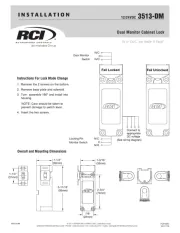
Pre-Installation Instructions
1. This product must be installed according to all applicable
building and life safety codes.
2. Due to the variety of mounting configurations available with
this product, a survey and assessment of the physical area
in which the product will be installed must be performed.
3. The door frame must be inspected and deemed
structurally sound prior to installation of the mechanical
electromagnetic lock. The structural integrity of the
mounting surfaces must be strong enough to meet or
exceed the holding force of the product.
4. The product must be protected from potential damage due
to intruders or tampering.
5. The product should be installed in a location that will not
hinder or create a potential safety hazard to authorized
personnel accessing the protected area.
6. Because mechanical electromagnetic locks are used in a
variety of applications and different door frame
configurations, an experienced installer with knowledge
of this product must make a determination of the optimal
mounting method for this specific application.
7. The components, hardware, installation instructions and
mounting template included with this product are intended
for use on outswinging doors.
8. Do not install this product on the exterior of buildings.
9. Do not use as a doorstop. This will void warranty.
10. Installation of this product should be done by an
experienced installer with knowledge of this product.
NOTE: It is highly recommended that thread locking compound
be applied to all screws during installation to reduce chance of
screws loosening over extended time.
ISEM-MAG1500 PCN15047
R08/15GR
Introduction
PLEASE DELIVER ALL INSTALLATION INSTRUCTIONS TO
THE END-USER UPON COMPLETION OF THE INSTALLATION.
Mechanical Electromagnetic Lock with bi-colored Light
Panel; EM-MAG1500 is a newly developed lock
integrated with mechanical and electromagnetic design.
EM-MAG1500 has significant low carbon foot print with
low power consumption, less material used
from its unique compact size compared to traditional
Mechanical Electromagnetic Locks. EM-MAG1500 has a
holding force up to 682Kg (1500 lb) with Preload feature
up to 60Kg (132 lb) and Impact Resistance of 100J
or 74 ft-lbf .
The lock Light Panel indicates the door status, based
on the Door Status Sensor (DSS), and Lock Status Sensor
(LSS).
The EW feature provides Early Warning Output signals
when an external force larger than 6~10Kg (13-22 lb)
is applied on the locked door leaf.
Door Open Red
Door Closed Green
© 2015 RutheRfoRd ContRols Intl | A doRMA GRoup CoMpAny
www.rutherfordcontrols.com • Phone: 1.800.265.6630 • fax: 1.800.482.9795 • e-mail: sales@rutherfordcontrols.com
EM-MAG1500 Mechanical Electromagnetic Lock
Installation Instructions (Continued)
Electrical Specifications:
Inspection and Maintenance
This product and all related accessories or parts must be inspected and
maintained on . Contacting surfaces of the mechanical a quarterly basis
electromagnetic lock and armature plate must be kept free of contaminating
materials. Surfaces must be cleaned periodically with a non-abrasive cleaner.
All mounting fasteners must be inspected on . When a quarterly basis
properly installed, the ends of the armature plate allow a slight movement
but the plate will feel secure when grasped at the bolt. There should be
no movement to the mounting bracket or housing of the mechanical
electromagnetic lock.
For added safety, thread locking compound has been provided for the
armature plate bolt and the four captive mechanical electromagnetic lock
mounting screws.
WARNING: Improper installation, maintenance, inspection or usage of
the product or any related accessories or parts may cause the mechanical
electromagnetic lock, armature plate and associated hardware to disengage
and fall, causing serious bodily injury and property damage. Rutherford
Controls Int’l Inc. and/or Rutherford Controls Int’l Corp. will not be liable to the
installer, purchaser, end user or anyone else for damage or injury to person or
property due to improper installation, care, storage,handling, maintenance,
inspection, abuse, misuse or act of God or nature involving this product or any
related accessories or parts.
RED - 12/24 VDC POSITIVE
BLACK - 12/24 VDC NEGATIVE
YELLOW x 2 - LSS OUTPUT 24 VDC .1 A
PINK - N/C
ORANGE - COM - EW1 50 VDC .3 Amp
PURPLE - N/O
WHITE - N/C
BROWN - COM - EW2 50 VDC .3 Amp
GRAY - N/O
BLUE/BLUE - DSS 30 VDC .3 Amp
}
}
Input:
12/ 24VDC± 10% Jumper Selectable (Fig 1a)
Current Draw:
.24A @ 12VDC .12A @ 24VDC
Lock Status Sensor (LSS):
Reed switch indicating a bond between Armature and Lock
(Closed circuit when Lock is powered and armature is in
place.)
Rated .1A max. @ 24VDC.
Door Status Sensor (DSS):
Reed switch indicating door position independent of Lock
power. (Closed circuit when armature is in place.)
Rated .3A max. @ 24VDC.
Ensure orange dots of armature and lock are aligned for
proper function.
EW1 & EW2:
Switches that are activated by unauthorized individuals
applying 6~10Kg (13- 22 lbs) of force on the door when
Lock is energized.
SPDT dry contacts 50 VDC @ .3A
12 VDC
24 VDC
Fig. 1a
Fig. 1
2 © 2015 RutheRfoRd ContRols Int’l | A doRMA GRoup CoMpAny
www.rutherfordcontrols.comPhone: 1.800.265.6630 • fax: 1.800.482.9795 • e-mail: sales@rutherfordcontrols.com


Produkt Specifikationer

Mærke: Dormakaba
Kategori: Ikke kategoriseret
Model: RCI EM-MAG1500

Har du brug for hjælp?

Hvis du har brug for hjælp til Dormakaba RCI EM-MAG1500 stil et spørgsmål nedenfor, og andre brugere vil svare dig