keep it for the life of the product passing it on to any subsequent holder of the product. Read all these
with longer life of the product itself.
product.
CONTACTS
YOUR DRAPER STOCKIST
TADH1220
2. CONTENTS
1. TITLE PAGE
1.1 INTRODUCTION .........................................................................................................2
1.2 REVISION HISTORY...................................................................................................2
1.3 UNDERSTANDING THIS MANUAL ............................................................................2
1.4 COPYRIGHT NOTICE .................................................................................................2
2. CONTENTS
2.1 CONTENTS.................................................................................................................. 3
3. WARRANTY
3.1 WARRANTY.................................................................................................................4
4. INTRODUCTION
4.1 SCOPE.........................................................................................................................5
4.2 SPECIFICATION ..........................................................................................................5
4.3 HANDLING AND STORAGE........................................................................................5
5. HEALTH AND SAFETY INFORMATION
5.1 GENERAL SAFETY INSTRUCTIONS FOR POWER TOOL USE ...............................6
5.2 ADDITIONAL SAFETY INSTRUCTIONS FOR NAILER/STAPLERS........................... 7
5.3 RESIDUAL RISK ..........................................................................................................7
5.4 SAFETY INSTRUCTIONS FOR MAINS POWERED CHARGERS
AND BATTERY PACKS................................................................................................ 8
5.5 CONNECTION TO THE POWER SUPPLY (CHARGER). ........................................... 9
6. TECHNICAL DESCRIPTION
6.1 IDENTIFICATION .......................................................................................................10
7. UNPACKING AND CHECKING
7.1 PACKAGING .............................................................................................................. 11
7.2 D20 MULTI-TOOL INTERCHANGEABLE BATTERY SYSTEM ................................. 11
7.3 WHAT’S IN THE BOX................................................................................................. 11
8. PREPARING THE NAILER/STAPLER
8.1 BATTERY PACK CHARGING .................................................................................... 12
8.2 BATTERY PACK PROTECTION FEATURES ............................................................ 13
8.3 BATTERY PACK CHARGE STATUS.......................................................................... 13
8.4 BATTERY LIFE EFFICIENCY AND CHARGING ADVICE ......................................... 13
8.5 LOADING NAILS AND STAPLES ..............................................................................14
9. BASIC NAILER/STAPLER OPERATIONS
9.1 SINGLE FIRING MODE ............................................................................................. 15
9.2 CONTACT FIRING MODE ......................................................................................... 15
9.3 DEPTH ADJUSTMENT WHEEL................................................................................. 15
9.4 LED WORKLIGHTS ................................................................................................... 15
10. MAINTENANCE AND TROUBLESHOOTING
10.1 MAINTENANCE .........................................................................................................16
10.2 UNBLOCKING JAMMED FASTENERS .....................................................................16
11. OPTIONAL ACCESSORIES
11.1 OPTIONAL ACCESSORIES........................................................................................ 17
12. DISPOSAL
12.1 DISPOSAL .................................................................................................................18
12.2 BATTERY PACK DISPOSAL INFORMATION ............................................................ 18
13. EXPLANATION OF SYMBOL
S
13.1 EXPLANATION OF SYMBOLS .................................................................................. 19
DECLARATION OF CONFORMITY .............................................................................. ENCLOSED
1. TITLE PAGE
4. INTRODUCTION
4.1 SCOPE
Ideal for upholstery and furnishing applications and also suitable for repairing fence panels or installing
hardboard.
As part of our core range, this product is suitable for enthusiasts and tradespeople alike. Any
application other than that it was intended for, is considered misuse.
4.2 SPECIFICATION
Stock No’s. ................................................................................................................00646 & 55740
Part No’s. .........................................................................................................D20NSSET & D20NS
Maximum operations per minute .................................................................................................... 60
Fastener capacities:
Staples (maximum No.100pcs) ............................................................... 19 – 40mm (Type 90)
Nails (maximum No.100pcs) ............................................... 20 – 50mm (18 Gauge brad nails)
Sound pressure level (LpA)*:
............................................................................................. 88.1dB(A)
Sound power level (LWA)**:
................................................................................................ 92.1dB(A)
Uncertainty (K): .......................................................................................................................... 3dB(A)
Vibration level........................................................................................................... 3.583 ± 1.5m/s²
Weight (machine only)............................................................................................................... 2.7kg
Battery pack (55740 sold separately):
Part No.......................................................................................................................... D20B2.0AH
Type ....................................................................................................................................... Li-ion
Rated Voltage ........................................................................................................................... 20V
Rating .................................................................................................................................... 2.0Ah
Chargers (55740 sold separately):
Part No............................................................................................................................... D20BCS
Rated Voltage ....................................................................................................................... 230V~
Rated Frequency ..................................................................................................................... 50Hz
Rated D.C. output voltage ........................................................................................................ 20V
Rated D.C. output current ...................................................................................................... 1.65A
Protective device rated current .................................................................................................... 8A
Construction ........................................................................................................................ Class II
* Continuous A-Weighted Sound Pressure Level at the workstation in accordance to and declared
according to EN60745.
** The typical A-weighted noise level determined according to EN60745.
4.3 HANDLING AND STORAGE
– Care must be taken when handling this product.
● Dropping this power tool could have an effect on its accuracy and could also result in personal
injury. This product is not a toy and must be respected.
– Environmental conditions can have a detrimental effect on this product if neglected.
● Exposure to damp air can gradually corrode components.
● If the product is unprotected from dust and debris, components will become clogged.
● If not cleaned and maintained correctly or regularly, the machine will not perform at its best.
10. MAINTENANCE AND TROUBLESHOOTING
5. HEALTH AND SAFETY INFORMATION 9. BASIC NAILER/STAPLER OPERATIONS
Hold handle firmly with magazine flat to work piece
forming a 90° (FIG.8).
9.1 SINGLE FIRING MODE – FIG. 9
Push the single/contact firing switch
(9)
to the left
side. Single Firing is good for precision placement .
– Depress the safety contact pin
(4)
against the
work piece
– Squeeze the trigger
(1)
to fire the staple or nail.
– Release the trigger and safety contact pin after
firing.
Fire next staple or nail, repeat step 2 and step 3.
The safety contact pin must be depressed before the
trigger is squeezed.
9.2 CONTACT FIRING MODE – FIG. 10
Push the single/contact firing switch
(9)
to the right
side. Contact Firing is good for convenient and quick
firing.
– Squeeze the trigger
(1)
, don’t release.
– Depress the safety contact pin
(4)
against the
work piece to fire the nail or staple. Keep the
trigger switched to the ‘FIRE’ position.
– Release safety contact pin after firing.
– Fire the next staple or nail, repeat step 3
The trigger switch must be kept to the ‘FIRE’ position
each time the safety contact pin is being depressed.
Do not keep the trigger depressed when the tool is
not in use to prevent accidental firing.
9.3 DEPTH ADJUSTMENT WHEEL –
FIG. 11
Depth adjustment controls the amount of force at
which fastenings are fired into surfaces. This helps to
protect work surfaces and also allows proper setting
of nail heads
– Turn the depth adjustment wheel
(3)
to the right.
The nail/staple will be fired into the surface at a
greater depth.
– Turn the depth adjustment wheel to the left. The
nail/staple will be fired into the surface at less
depth.
9.4 LED WORKLIGHTS
The nailer/stapler contains 2 × LED worklights, useful
when working in low light level environments.
– The lights are operated using the switch
(11)
located close to the firing trigger
(1)
.
3. WARRANTY
3.1 WARRANTY
Draper tools have been carefully tested and inspected before shipment and are guaranteed to be free
from defective materials and workmanship.
Should the tool develop a fault, please return the complete tool to your nearest distributor or contact:
Draper Tools Limited, Chandler's Ford, Eastleigh, Hampshire, SO53 1YF. England.
Telephone Sales Desk: (023) 8049 4333 or:
Product Helpline (023) 8049 4344.
A proof of purchase must be provided.
If upon inspection it is found that the fault occurring is due to defective materials or workmanship,
repairs will be carried out free of charge. This warranty period covering labour is 12 months from the
date of purchase except where tools are hired out when the warranty period is 90 days from the date
of purchase. The warranty is extended to 24 months from the date of purchase for parts only. This
warranty does not apply to any consumable parts, any type of battery or normal wear and tear, nor
does it cover any damage caused by misuse, careless or unsafe handling, alterations, accidents, or
repairs attempted or made by any personnel other than the authorised Draper warranty repair agent.
Note: If the tool is found not to be within the terms of warranty, repairs and carriage charges will
be quoted and made accordingly.
This warranty applies in lieu of any other warranty expressed or implied and variations of its terms are
not authorised.
Your Draper warranty is not effective unless you can produce upon request a dated receipt or invoice
to verify your proof of purchase within the warranty period.
Please note that this warranty is an additional benefit and does not affect your statutory rights.
Draper Tools Limited.
5. HEALTH AND SAFETY INFORMATION
Wait for the machine to stop. Unless the machine is fitted with a safety brake, some parts may
continue to move due to momentum. Wait for all parts to stop, then unplug it from the power supply
before making any adjustments, carrying out maintenance operations or just finishing using the tool.
Remove and check setting tools. Some machinery requires the use of additional tools or keys to set,
load or adjust the power tool. Before starting the power tool always check to make certain they have
been removed and are safely away from the machine.
Prevent unintentional starting. Before plugging any machine in to the power supply, make sure the
switch is in the OFF position. If the machine is portable, do not hold the machine near the switch and
take care when putting the machine down, that nothing can operate the switch.
Carefully select an extension lead. Some machines are not suitable for use with extension leads. If
the tool is designed for use outdoors, use an extension lead also suitable for that environment. When
using an extended lead, select one capable of handling the current (amps) drawn by the machine in
use. Fully extend the lead regardless of the distance between the power supply and the tool. Excess
current (amps) and a coiled extension lead will both cause the cable to heat up and can result in fire.
Concentrate and stay alert. Distractions are likely to cause an accident. Never operate a power tool if
you are under the influence of drugs (prescription or otherwise), including alcohol or if you are feeling
tired. Being disorientated will result in an accident.
Have this tool repaired by a qualified person. This tool is designed to conform to the relevant
international and local standards and as such should be maintained and repaired by someone
qualified, using only original parts supplied by the manufacturer. This will ensure the tool remains safe
to use.
5.2 ADDITIONAL SAFETY INSTRUCTIONS FOR NAILER/STAPLERS
Always assume that the nailer/stapler contains fasteners. Careless handling of the tool can result
in unexpected firing of fasteners and personal injury.
Do not point the stapler/nailer towards yourself or anyone nearby. Unexpected triggering will
discharge the fastener causing an injury.
Do not operate the firing mechanism of the nailer/stapler unless the tool is placed firmly
against the workpiece. If the tool is not in contact with the workpiece, the fastener may be deflected
away from the target.
Disconnect the nailer/stapler from the battery pack if a fastener jams in the tool. Whilst removing
a jammed fastener, the tool could be accidentally activated if the battery pack is fitted.
Use caution whilst removing a jammed fastener. The mechanism may be under compression and
the fastener may be forcefully discharged.
Do not use the nailer/stapler for fastening electrical cables . It is not designed for electric cable
installation and may damage the insulation of electric cabling, resulting in electric shock or fire
hazards.
Do not use the nailer/stapler whilst working off of ladders or scaffolding. Falls from heights carry
an increased risk of further serious injury to the user, especially if the nailer/stapler is set to contact
firing mode
5.3 RESIDUAL RISK
Important note: Although the safety instructions and operating manuals for our tools contain extensive
instructions of safe working with power tools, every power tool involves a certain residual risk which
can not be completely excluded by safety mechanisms. Power tools must therefore always be
operated with caution!
5. HEALTH AND SAFETY INFORMATION
7. UNPACKING AND CHECKING
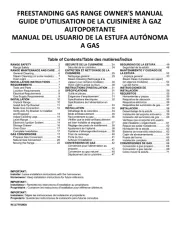
8.1 BATTERY PACK CHARGING –
FIGS. 1 – 2
This power product is either supplied “bare”,
without battery pack or charger (Stock No.55740),
or with a transformer/charger and one battery
pack (Stock No.00646).
Important: Only Draper designated battery packs and
chargers can be used in conjunction with this product.
Use of any other third party battery packs/chargers
with this product is considered misuse and will
invalidate the product’s warranty.
Once connected to the mains supply, recharging of
the battery can be left generally unsupervised,
requiring minimal attention. Complex circuit
construction monitors the battery condition, adjusting
the recharge current to suit. When the recharge cycle
is complete, to maintain the full capacity, a low output
current will continue as required.
Warning! Check the condition of the charger and
battery prior to each charge. If there is any sign of
damage then do not commence charging, seek advice
from Draper Tools.
The battery pack is supplied un-charged and must be
charged before initial use.
To charge the battery pack (12), it must first be
removed from the tool.
To release the battery pack:
– Press the battery release button (12.1) and gently
slide the battery pack off (Fig.1).
– Plug the battery charger (16) unit into a 230V/AC
13amp three pin supply socket.
– The red LED (16.1) will illuminate to show the
charger has power.
– Slide the battery into the charger (the battery is
shaped to fit into the charger one way only.
– After a few seconds delay, the red LED (16.1) will
flash to show that charging has begun, then illuminate solid red.
– Whilst the battery is charging, the green LED (16.2) will flash, (the red LED will go from flashing to
constant red.
– When the battery is fully charged when the green LED stops flashing and remains a constant
green. The red LED will extinguish.
Caution: Do not pull the plug out of the power supply by pulling on the cord. Make sure to grasp the
plug when removing from power supply to avoid damaging the cord.
To remove the battery from the battery charger:
– Supporting the battery charger with hand, pull out the battery from the battery charger.
Caution: If the battery charger has been in continuous use it will be hot. Once the charging has been
completed, leave the charger 15 minutes to cool until next use.
5.4 SAFETY INSTRUCTIONS FOR MAINS POWERED CHARGERS
AND BATTERY PACKS
Chargers
– The charger is for indoor use only.
– Prior to plugging the charger in to the supply, check that the plug and the cable are in good
repair. If either are damaged, have the defective item replaced immediately by a suitably
qualified person. If the casing of the battery charger is damaged, it is good policy to have the
charger checked over by a suitably qualified person.
– Only use a correctly rated mains outlet to provide power, do not plug into site generators, attach
to engine generators or D.C. sources. Do not use a mains socket outlet that is not switched.
– Use the correct Draper charger in conjunction with it’s corresponding battery pack (consult the
Draper website for more information or to find your local stockist).
– Do not charge any other batteries with Draper chargers. Any other application is considered
misuse.
– Do not attempt to charge battery packs that are too hot (over 30ºC) or too cold (under 5ºC), if
these conditions apply set the battery pack aside to “normalise” before proceeding with the
charging operation.
– Set up the charger and cable in a safe place where it won’t be knocked, tripped over, stepped on,
etc. and where it is well ventilated. Make sure the ventilation slots in the charger case are not
obstructed, plug the charger into the socket outlet.
– Inspect the battery pack for damage, if it is undamaged, plug it into the charger, ensuring the
correct orientation. (Most chargers and batteries have ‘keys’ etc, to make sure the battery pack is
not inserted incorrectly, if you are having to ‘force’ the battery pack into the charger, the chances
are you have it the wrong way round, check and try again.)
– Switch the charger on and check that the correct indicators illuminate, allow the battery pack to
charge (see the specific instructions for your charger). Once charging is complete, switch the
charger off, remove the battery pack and store, repeat the procedure if you have more than one
battery pack to charge.
Caution: When the battery charger has been continuously used, the battery charger will be hot.
Once the charging has been completed, give 15 minutes rest until the next charge.
– After charging is complete, unplug the charger from the socket outlet by pulling on the plug. Do
not pull on the cable. Store the charger in a dry secure place.
– If, when the charger was switched on, the correct indications did not occur, leave for two or three
minutes to allow the charger to stabilise, if the correct indications occur, allow the charging cycle
to proceed as normal. If no indication appears at all, switch off, remove the battery pack, unplug
the charger, check that the charger contacts and the battery contacts are clean and repeat the
process. If there is still no indication, switch off, remove the battery pack, unplug the charger and
check the fuse. If the fuse is blown, replace and repeat the process. If the fuse blows again, or if
the fuse was intact, attempt no further action. Refer the charger to a suitably qualified person for
repair.
Battery packs
– Before charging, read the instructions.
– For indoor use. Do not expose to rain.
–
Only use Draper D20 battery packs with this product. Consult your Draper stockist for details.
– Do not charge any other manufacturer’s battery packs using Draper chargers. Any other
application is considered misuse.
– The battery must be removed from the appliance before it is recycled.
– The charger must be disconnected from the supply mains when removing the battery.
5. HEALTH AND SAFETY INFORMATION
(12)
20V Li-ion battery pack.
(13)
25mm 18 Gauge brad nails × 300.
(14)
19mm Type 90 staples × 100.
(15)
Hex key.
(16)
Transformer/charger.
- 3 -
- 19 -
- 5 -
- 6 -
- 4 -
- 7 -
- 8 -
- 9 -
- 10 - - 11 -
- 13 -
- 12 -
- 14 -
- 15 -
- 16 -
- 17 -
- 18 -
– The battery is to be disposed of in-line with local authority procedures.
– Do not use any other than the designated Draper batteries/chargers with this product.
– Do not crush, open or burn the battery. Exposure to potentially harmful materials may occur.
– In case of fire use CO2 or dry chemical extinguisher.
– Do not expose to high temperatures >50°C. The battery may degrade at high temperatures.
– Charge battery in conditions between 5°C to 30°C with the specified charger designed for this
battery.
– Do not use battery if it has been stored at 5°C or less. Allow it to “normalise” at room temperature
before usage/changing.
Warning!
● Leaking battery packs
– The electrolyte in battery packs is corrosive. Avoid contact with the skin.
– If contact is made, flush the area with running water, pat dry and seek medical attention and
advice at the earliest opportunity.
– Inform medical personnel that the contaminant is a “high alkaline, corrosive liquid”.
– If electrolyte comes into contact with the eyes, flush with copious amounts of water only.
Seek medical attention immediately, relaying the information above.
5.5 CONNECTION TO THE POWER SUPPLY (CHARGER)
Caution: Risk of electric shock. Do not open.
This appliance is supplied with a moulded 3 pin mains plug for your safety. The value of the fuse fitted
is marked on the pin face of the plug. Should the fuse need replacing, ensure the substitute is of the
correct rating, approved to BS1362 and ASTA or BSI Kite marked.
ASTA
BSI
The fuse cover is removable with a small plain slot screwdriver. Ensure the fuse cover is replaced
before attempting to connect the plug to an electrical outlet. If the cover is missing, a replacement must
be obtained or the plug replaced with a suitable type.
If a replacement plug is to be fitted this must be carried out by a qualified electrician.
The damaged or incomplete plug, when cut from the cable should be disabled to prevent connection to
a live electrical outlet.
This appliance is Class II† and is designed for connection to a power supply matching that detailed on
the rating label and compatible with the plug fitted.
If an extension lead is required, use an approved and compatible lead rated for this appliance. Follow
all the instructions supplied with the extension lead.
†
Double insulated : This product requires no earth connection as supplementary insulation is
applied to the basic insulation to protect against electric shock in the event of failure of the basic
insulation.
IMPORTANT
If using an extension lead, follow the instructions that came with your lead regarding
maximum load while cable is wound. If in doubt, ensure that the entire cable is unwound.
Using a coiled extension lead will generate heat which could melt the lead and cause a fire.
Li-ion
8. PREPARING THE NAILER/STAPLER
8. PREPARING THE NAILER/STAPLER
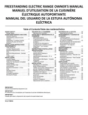
(1)
Trigger.
(2)
Cylinder.
(3)
Depth adjustment wheel.
(4)
Safety contact pin.
(5)
LED Worklights.
(6)
LED Firing status indicator.
(7)
Magazine (open, showing staples loaded).
(8)
Magazine release lever.
(9)
Single/contact firing switch.
(10)
Belt hook.
(11)
LED Lighting switch.
(12)
20V Li-ion battery pack.
10.1 MAINTENANCE
Regular inspection and cleaning reduces the
necessity for maintenance operations and will keep
your tool in good working condition.
10.2 UNBLOCKING JAMMED
FASTENERS – FIGS. 12 – 15
Although this nailer/stapler is fitted with an anti-jam
mechanism, should a fastening jam occur, follow the
instructions given below.
Note: You must remove any jammed nail/staple
before using the tool any further. Otherwise, it could
cause damage to the mechanism.
Warning! Remove the battery from the tool before
carrying out adjustment, servicing or maintenance.
Warning! Never look into the mechanism whilst the
unit is plugged in. Good practise would be to isolate
the nailer/stapler whenever loading/changing the
staples/nails.
– Slide open the magazine
(7)
and remove existing
staples or nails in the chamber.
– Remove the jammed fastener(s).
Should the jam prove too difficult to remove with pliers
alone, the plastic housing of the firing head can also
be removed to gain access to the jammed
mechanism.
– Remove the 2 hex bolts
(2.3)
from the front of the
firing head housing
(2.1)
using the hex key
supplied
(15)
.
– Remove the blockage using appropriate nose
pliers and re-assemble the front housing (opposite
procedure to above).
– Test that mechanism is free from any obstruction
by testing the nailer on a piece of scrap wood,
before re-inserting the nails or staples.
– Repeat the test with nails/staples loaded.
1.1 INTRODUCTION:
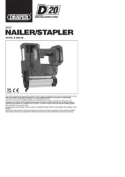
USER MANUAL FOR: 20V Nailer/Stapler
Stock No’s: 00646 (with battery charger and battery) and 55740 (bare)
Part No’s: D20NSSET & D20NS
As our user manuals are continually updated, users should make sure that they use
the very latest version.
Downloads are available from: http://drapertools.com/manuals
Draper Tools Limited Delta International BV
Hursley Road Oude Graaf 8
Chandler’s Ford 6002 NL
Eastleigh Weert
Hampshire Netherlands
SO53 1YF
UK
Website: drapertools.com
Product Helpline: +44 (0) 23 8049 4344
General Fax: +44 (0) 23 8026 0784
1.3 UNDERSTANDING THIS MANUALS SAFETY CONTENT:
WARNING! – Information that draws attention to the risk of injury or death.
CAUTION! – Information that draws attention to the risk of damage to the product or
surroundings.
1.4 COPYRIGHT © NOTICE:
Copyright © Draper Tools Limited.
Permission is granted to reproduce this publication for personal and educational use
only. Commercial copying, redistribution, hiring or lending is prohibited.
No part of this publication may be stored in a retrieval system or transmitted in any
other form or means without written permission from Draper Tools Limited.
In all cases this copyright notice must remain intact.
1.2 REVISIONS:
Date first published September 2018.
Date revised December 2020.
(2)
(4)(5)
(4)
12. DISPOSAL
12.1 DISPOSAL
– At the end of the machine’s working life, or when it can no longer be repaired, ensure that it is
disposed of according to national regulations.
– Contact your local authority for details of collection schemes in your area.
In all circumstances:
●
Do not dispose of power tools with domestic waste.
● Do not incinerate.
● Do not dispose of WEEE* as unsorted municipal waste.
13.1 EXPLANATION OF SYMBOLS
13. EXPLANATION OF SYMBOLS
99
Single value noise marking.
(Maximum declared A-Weighted
sound power level in decibels).
Read the instruction manual.
Wear protective gloves.
Do not abandon into the
environment.
Keep out of the reach of children.
Warning!
For indoor use only.
Do not expose to rain.
Short-circuit-proof safety
isolating transformer
Lithium-ion product.
WEEE –
Waste Electrical &
Electronic Equipment.
Do not dispose of Waste Electrical
& Electronic Equipment in with
domestic rubbish.
Class II construction
(Double insulated).
Polarity indication.
Rated voltage.
Do not incinerate or
throw onto fire.
Fuse.
130°
If the battery is charged when it is warm due to battery
use or exposure to sunlight, the battery will not be
recharged. In such a case, let the battery cool before
charging.
If the red indicator flickers rapidly at 0.2 second
intervals, check or and remove any foreign objects in
the charger’s battery slot. If there are no foreign
objects, it is probable that the battery or charger is
malfunctioning. Allow battery/charger to normalise and
try again. If a fault remains after trying this then
contact Draper Tools.
8.2 BATTERY PACK PROTECTION
FEATURES
Overcharging protection: This feature that ensures
that the battery pack can never be overcharged.
When the battery pack reaches full charge capacity,
the transformer/charger will automatically shut off,
protecting the internal components from being damaged.
Over-discharging protection: This feature will stop
the battery pack from discharging beyond the
recommended lowest safety voltage.
Overheating protection: The battery pack contains
an internal thermistor cut-off sensor which shuts off
the battery pack should it become too hot during
operation. This can happen if the tool is overloaded or
being used for extended periods. Up to 30 minutes
cooling time may be required, depending on ambient
temperature.
Current protection: Should the battery be
overloaded and the maximum current draw be
exceeded, the battery will shut off to protect the
internal components. The battery pack will resume
working once excessive current draw has returned to
normal, safe level.
Short circuit protection: If, for any reason, the battery pack was to short circuit, the short circuit
protection would immediately stop the battery pack from operating.
8.3 BATTERY PACK CHARGE STATUS – FIG. 3
To display the amount of charge left in the battery pack, press the charge level indicator button
(12.2)
.
8.4 BATTERY LIFE EFFICIENCY AND CHARGING ADVICE
– Avoid recharging at high temperatures.
A rechargeable battery will be hot immediately after use. If such a battery is recharged immediately
after use, its internal chemical substance will deteriorate, and the battery life will be shortened.
Leave the battery and recharge it after it has cooled for a while.
–
The battery should only be used and/or charged when battery temperature is between 5°C and 30°C.
– The battery needs to be warmed-up or cooled down in order to prevent damage to the batteries
internal components,
Note: If battery is too hot or too cold, allow it to ‘normalise’ before use or charging.
Note: Failure to warm up or cool down a battery could result in serious damage to the battery, charger
and user.
Note:
Remove the battery from the tool before
carrying out adjustment, servicing or maintenance.
8.5 LOADING NAILS AND STAPLES –
FIGS. 4 – 7
At the rear of the magazine
(7)
is the magazine
release lever
(8)
.
– To release it, press the locking lever forward and
slide out the magazine.
– Tilt the tool and place nails/staples into the track of
the magazine channel.
Make sure that the fasteners are placed correctly:
– Staples are placed against the profiled side of the
rail, the crown of the staple is in the uppermost
part of the magazine(legs are facing away from
the body of the tool).
– Nails are placed against the profiled side of the
rail, with the points of the nails facing downwards.
– Close the magazine cover until it engages with the
release button.
Note: The number of staples or nails left in the
magazine can be read using the viewing window
(7.1)
.
– Re-attach battery pack to tool.
Warning! Do not place fasteners of different length.
Do not place staples and nails mixed together.
The magazine has capacity for 18 gauge nails at 20 –
50mm sizes. A maximum of 100 nails can be loaded
into the magazine at one time.
The magazine will accept Type 90 staples at 19 –
40mm sizes. A maximum of 100 staples can be
loaded into the magazine at one time.
* Waste Electrical & Electronic Equipment.
12.2 BATTERY PACK DISPOSAL INFORMATION
Warning!
– Do not put battery pack in fire or mutilate – cells may burst or release toxic materials.
– Do not short circuit cells, may cause burns.
– The battery pack must be removed from the appliance before it is scrapped.
– The battery pack is to be disposed of safely.
– Do not mutilate batteries, corrosive electrolyte will be released.
– Do not dispose of batteries or cells in a charged condition.
Expired batteries must be recycled/disposed of in accordance with the appropriate regulation or
legislation. They should be returned to your local warranty agent/stockist.
Wear ear defenders and
safety glasses.
FIG.1
FIG.2
FIG.6
FIG.5
FIG.4
FIG.7
FIG.8
FIG.9
FIG.10
FIG.11
FIG.12
FIG.13
FIG.14
FIG.15