ENTES ELR-30-A Manual
ENTES
Ikke kategoriseret
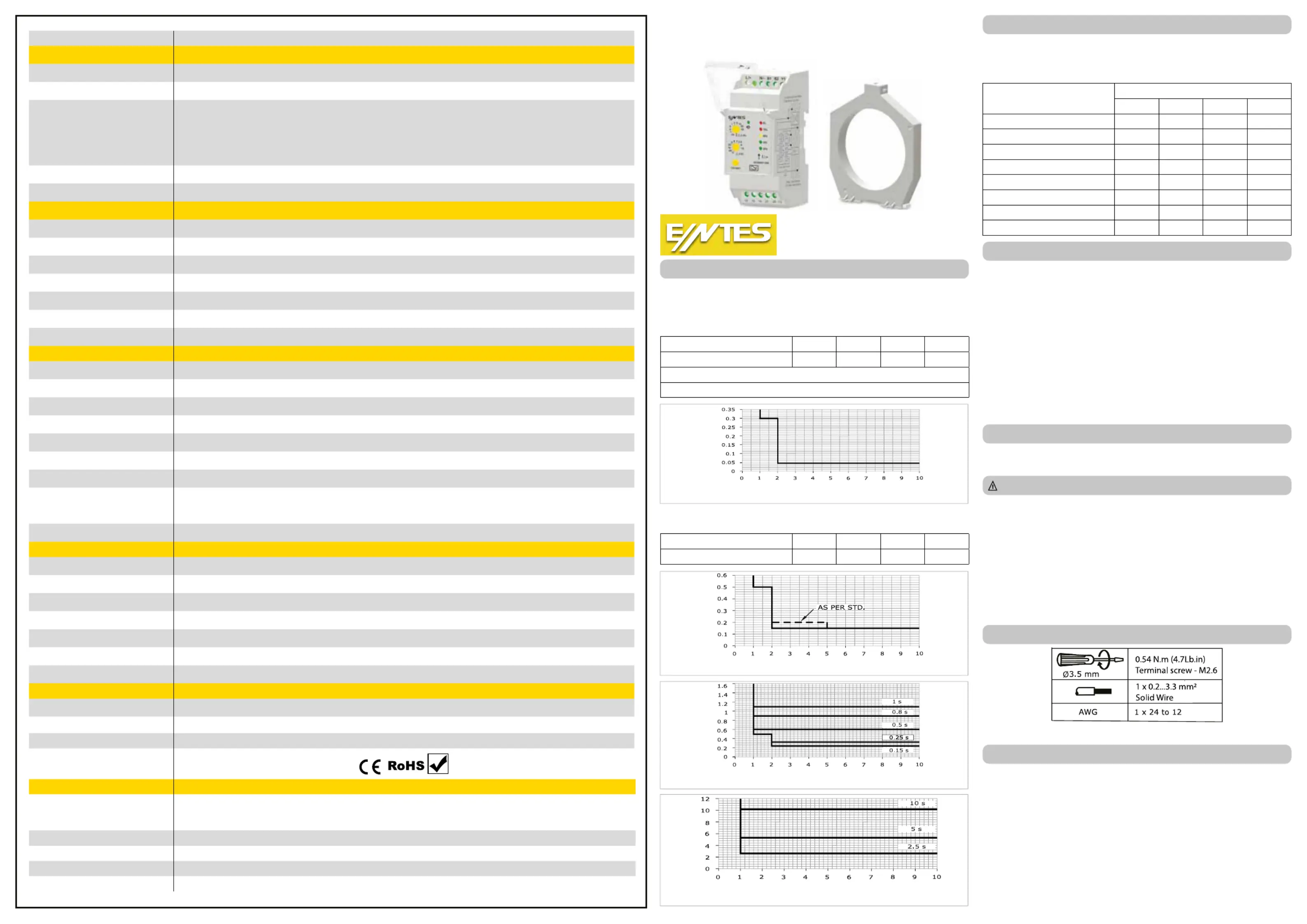
ELR-30-A
| Mærke: | ENTES |
| Kategori: | Ikke kategoriseret |
| Model: | ELR-30-A |
Har du brug for hjælp?
Hvis du har brug for hjælp til ENTES ELR-30-A stil et spørgsmål nedenfor, og andre brugere vil svare dig
Ikke kategoriseret ENTES Manualer

10 Oktober 2025

9 Oktober 2025

8 Oktober 2025

8 Oktober 2025

8 Oktober 2025

8 Oktober 2025
8 Oktober 2025

8 Oktober 2025

8 Oktober 2025

8 Oktober 2025
Ikke kategoriseret Manualer
- Wolverine
- KONIFERA
- Mackie
- Akaso
- Fresca
- Iris Ohyama
- Elgato
- CHINT
- DOK
- Rommelsbacher
- Havis
- Trumeter
- Neets
- Aquael
- BlueDri
Nyeste Ikke kategoriseret Manualer
31 Oktober 2025
31 Oktober 2025
31 Oktober 2025
31 Oktober 2025
31 Oktober 2025
31 Oktober 2025

31 Oktober 2025
31 Oktober 2025

31 Oktober 2025
31 Oktober 2025