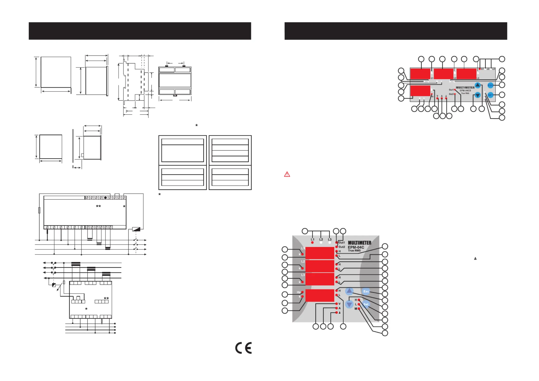
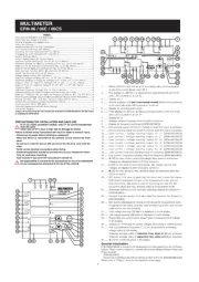
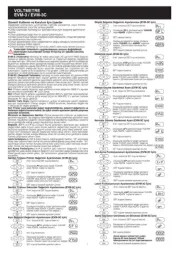
ENTES EPM-04-DIN Manual

ENTES Måleudstyr EPM-04-DIN

Læs gratis den danske manual til ENTES EPM-04-DIN (4 sider) i kategorien Måleudstyr. Denne vejledning er vurderet som hjælpsom af 24 personer og har en gennemsnitlig bedømmelse på 4.4 stjerner ud af 12.5 anmeldelser. Har du et spørgsmål om ENTES EPM-04-DIN, eller vil du spørge andre brugere om produktet?

Side 1/4
1
MULTIMETER
EPM-04 / 04C / 04CS
INDEX
Precautions for Installation and Safe Usage.........................................................................1
Front Panel and Usage of Buttons.............................................................................1
General Information and Applications.............................................................................1
Using the Buttons............................................................................................2
Transformer Menu (Ctr / trn / Utr / ConnECtýon) ........................................................................2
User Password Settings (Pin Menu).......................................................................2
Act ivat ing the User Password (Pin Act Menu)......................................................2
Changing the User Password (Pin CHg Menu).........................................................2
Output Setting Menu ..............................................................................3
Current Setting Menu (SP Current Menu) ................................................................3
High/Low Current Settings (SP Cur Hý, SP Cur Lo Menu)..........................................3
Hysteresis Sett ings for High/Low Currents (I-H Hys, I-L Hys Menu).................3
Delay-on Time for High/Low Current s (I-H ond, I-L ond Menu)..............................3
Delay-off Time for High/Low Currents (I-H ofd, I-L ofd Menu).......................................3
Start and Auto Function (StArt dEL and Auto rSt Menu).........................................4
Instant Trip Function (CUr ýnS trP Menu).................................................................4
Voltage Setpoint Menu (SP Volt Menu) ..................................................................4
High/Low Voltage Set tings (SP UoL Hý, SP UoL Lo Menu)..................................4
Hyst eresis Sett ings f or High/Low Volt ages (U-H Hys, U-L Hys Menu)............5
Delay-o n T im e f or High/ Low Vo ltages (U-H ond, U-L ond Menu).. ... ... .....5
Delay-of f Time f or High/Lo w Volt ag es (U-H of d, U-L of d Menu)...... ....... ...5
Frequency Menu .........................................................................................................6
High/Low Frequency Set tings (Frq Hý, Frq Lo Menu).............................................6
Hysteresis Settings for High/Low Frequencies (F-H HyS, F-L HyS) ..............................6
Delay-on / Delay-off T ime for Hig h/Low Frequencies (Frq ond , Frq oFd )....6
Phase Sequence (Voltage Sequence Menu) and Instant Trip (UoL ýnS trP Menu) Menu ........6
Erasing the Max., Min. and Max. Demand Values (Reset Menu)........................6
Demand Time for Demand and Max. Demand (dE tý Menu)....................................................7
Communication Menu (RS-485) .........................................................................7
Technical Features and Default Factory Settings ................................................................7
Connection Diagram ................................................................................................8
Output, SP Current and SP Volt menus are available for EPM-04C/04CS; RS-485 menu
is available for EPM-04CS.
Dimensions
General information
EPM-04/04C/04CS is designed for measuring Phase current, frequency, neutral
cur r e nt and vol tag e s (Phase -Pha se and Pha se-Neut r al) in a
3-Phase system.
EPM-04C/04CS;
Device has 2 warning
output
which named as Out1 and Out2. (NO-Normally
Open) Please refer to Output menu for the functions of the relays.
Connection Diagram
MULTIMETER
EPM-04 / 04C / 04CS
8
A4034 / Rev.8
Available only for EPM-04C/04CS
Available only for EPM-04CS
Panel Cut-out
91mm
91mm
Type PR 19 (96x96)
70mm
Wall 79.3mm
90mm
Tip 19
50mm
1 .......
Phase LEDs:The LEDs turn on when the voltage value, which is applied
to one of the current inputs, reach 30 V
2 ....... First displays k LED (for L1). Measurement parameter is the unit of kilo
when LED is turned on. ie: kA, kV
3 ....... Display for
L1.
4 ....... Second displays k LED (for L2). Measurement parameter is the unit of kilo
when LED is turned on. ie: kA, kV
5 ....... Display for
L2.
6 ....... Third displays k LED (for L3). Measurement parameter is the unit of kilo
when LED is turned on. ie: kA, kV
7 ....... Display for
L3.
8 ....... Displays network frequency when Hz LED is turned on.
9 ....... LED for neutral current. Measurement parameter is displayed in unit of k
kilo when this LED is turned on.
10 ....... Display for neutral current and frequency (for EPM-04C/04CS).
11 .......First warning output LED (Out1). Turned on when the output is activated.
12 .......Second warning output LED (Out2). Turned on when the output is activated.
13 .......Over current / voltage warning output for L1. (EPM-04C/04CS)
14 .......Low current / voltage warning output for L1. (EPM-04C/04CS)
15 .......Over current / voltage warning output for L2. (EPM-04C/04CS)
16 .......Low current / voltage warning output for L2. (EPM-04C/04CS)
17 .......Over current / voltage warning output for L3. (EPM-04C/04CS)
18 .......Low current / voltage warning output for L3. (EPM-04C/04CS)
19 ....... Over current / frequency warning output for frequency and neutral current
(EPM-04C/04CS).
20 .......Low current / frequency warning output for frequency and neutral current
(EPM-04C/04CS).
21 .......Monitoring the L1, L2, L3 voltages values when V LED is turned on and
displays the frequency in 4th display.
22 .......Monitoring the L1, L2, L3 currents values when A LED is turned on and
displays the neutral current in 4th display.
23 ....... Indicates the activating delta connection when is turned on. Neutral
current protection is disactivated even if is activated.
24 ....... LED for max. instant current and voltage. Max. instant currents and H
voltages are displayed when this LED is turned on.
25 ....... LED for min. instant current and voltage. Min. instant currents and L
voltages are displayed when this LED is turned on.
26 ....... LED for max. demand. Max. demand values are displayed when this M
LED is turned on.
27 .......SET button. It is used to enter into the menu and to save the values.
If SET button is pressed for 3 sec. in the measurement mode, you can
enter into menus. This button is used for monitoring the max. (H), Min.
(L) current values and max. demand values in measurement mode.
28 ....... Downward selection button.
29 .......Upward selection button.
30 .......
ESC button. Escaping from the menu. And also used for switching off the
Latch function while this function has activated.
Failure to follow those instructions will result in death or serious injury.
- Disconnect all power before working on equipment.
- When the device is connected to the network, do not remove the front
panel.
- Do not try to clean the device with solvent or the like.Only clean with dry
cloth.
- Verify correct terminal connections when wiring.
- Electrical equipment should be serviced only by your component seller.
- Only for rack panel mounting.
- Fuse must be F type and limit value doesnt exceed 1A.
- No responsibility is assured by manufacturer or any of its subsidiaries
for any consequences arising out of the use of this material.
~
Un
Out 2 Out 1
PK-26
I
L3
I
L2
I
L1
k l
K L
k l
K L
kl
K L
L1 L2 L3 N
GND A B TR
N
L1
L2
L3
1
A
Current Measurement
Inputs
Auxiliary
Supply
Relay utputo
System
Choose according to
contactor current
Voltage Measurement
Inputs
RS485
70mm
79.3mm
90mm
Type PR 19 (96x96)
96mm
96mm
60.6
106.0
10.8 30.1 7.6 9.5
26.5 21.5
53.0
58.0
10.0
8.5
14.0
45.0
90.0
Type PK 26
*
**
12 4 63 5 7
8 9
10
19 20
30
27
28 29 25
24
26
21 22 23
12 11
17
18
15
16
13
14
2
3
4
5
6
7
8
9
10
15
17
19
18
16
13
14
2021 22 23
27
25
24
30
28
29
26
1 11 12
Note: For CT-25 models:
PR-19
k l
K L
k l
K L
k l
K L
IL1 IL2 IL3
Out 1 Out 2 GND B A TR
17 18 19 20
RS485
System
N
L1
L2
L3
1 A
L1
L2
L3
N
Current Measurement Inputs
Auxiliary
Supply
1 2 3 4 5 6
11 12
Output Relay
13 14 1 165
Choose according to
contactor current
7 8 9 10
Voltage Measurement Inputs
In CT-25 (120A) compliant models, only CT-25 current transformer
must be used.
Other type of CTs have a high risk to damage to device.
PRECAUTIONS FOR INSTALLATION AND SAFE USE
Summary of the Contact Operations
Voltage
Frequency
Current
Phase Seq.
Voltage
Frequency
Current
Under
Under
Under
Over
Over
Over
ALTERNATIVE 2 (H-L)
Current
Voltage
Frequency
Phase Seq.
Under/Over
Under/Over
Under/Over
ALTERNATIVE 1 (U-I)
Out 1
Out 2
-->
-->
-->
-->
-->
-->
-->
-->
-->
Valid for EPM-04C/04CS
k: When CT-25 is used, Red cable is connected to k terminal.
l: When CT-25 is used, Black cable is connected to l terminal.
User Password Setup:
In this menu user password is defined and activated.
You must define and activate a 4 digit user password for preventing device
settings from the illegal usage.
There are 2 sub menu in the Pýn menu.
ESC
SET
Press ESC button one by
one until SAU E SEt yES
is displayed.
Press SET button. When
SAU E SEt yES is
displayed (If you press
ESC button or choose nooption instead of yES then new data will
be cancelled and previous value will be activated).
This menu is used for activating the user password.
After the user password is activated for entering to the menus;
if the button is pressed for sec., while the instant values3
are observed, user password is required. If the user password
is entered wrong device does not latch.
Note: Factory default value of user password is 0000
Activating the user password :
Press SET button for 3 sec. (trA Fo menu is displayed)
Find the Pýn menu by scrolling UP/DOWN buttons.
Press SE T button (Pýn ACt IUA tE is displayed.)
SET
SET
SET
S ET
2
MULTIMETER
EPM-04 / 04C / 04CS
Using the Buttons:
Some buttons and button groups are used for the below special function
when device is in the measurement mode (Without selecting a menu).
: Switching to the previous menu and escaping the programming
menu without saving the changes.
If the Latch function is turned on (EPM-04C/04CS); output will be
released when current(s) of system is exceed the defined values.
When the systems current turns back to normal values then output
doesnt react. Output can be trigged by the ESC button.
Monitoring for phase currents (A LED is activated) or phase voltages
(V LED is activated).
Used for changing the menu settings and parameters in programming
mode.
ESC
Commissioning the EPM-04C/04CS and menu setting:
Energize the device after implementing the connections respected to the
user manual.
Enter the proper menu settings in order to correct measurements and
applications.
Current Transformer Ratio Setup:
In this menu, current transformer ratio is set between 1 - 2000.
(This menu is not available in the devices which are adapted
with CT-25.)
Note: If the current transformer is not used between the system
and device, current transformer ratio is entered as 1.
Example: If a current transformer which has a ratio of 30/5A is
used between the system and device;
Curren t transformer ratio is entered as = 30/5 = 6.
SET : Used for monitoring min. / max. currents and voltages or max. demand
values. Switching to the programming mode if it pressed for 3 sec. In
programming mode; it is used for switching to the menu and saving
changes for the parameters.
SET
SET
ESC
SET
Press SET button; trA Fo Ctr menu is displayed (In CT-25 adapted
devices, trA Fo trn is displayed instead.)
( trA Fo Utr or Con nEC týo n menu can be displayed by scrollingNot:
the UP/DOWN buttons.)
Press SET button. Blinking the first digit of displayed value appears.
(trA Fo Utr or Con nEC týo n menu can be
programmed similarly.)
Enter the blinking digit value by scrolling
UP/DOWN buttons. Switch to the other
digits by using SET button, use ESC button
to go to previous digit. After you entered
the last digit press SET button, trA Fo Ctr
is displayed.
(Data is entered but is not
activated yet. For activating the new data
please follow the below steps).
SET
Press SET button for 3 sec. (trA Fo menu is displayed)
Voltage Transformer Ratio:
In this menu, voltage transformer ratio is set between 0000,1 - 4000,0.
Note: If the voltage transformer is not used between the system and
EPM-04, voltage transformer ratio is entered as 1.
Example: If a voltage transformer which has a ratio of 34.5KV/100V
is used between the system and device; Voltage transformer ratio
is entered as 345. (34500/100)
Selecting the Connection Type :
Connection can be selected as Star or Delta in this menu.
Phase-Neutral voltage monitoring can be implemented if the Star
connection is selected.
Phase-Phase voltage monitoring can be implemented if the Delta
connection is selected.
NOTE: When the Delta connection is selected, neutral current
monitoring can not be implemented even if it is activated.
SET
Press ESC button one by one until
SAU E SEt yES is displayed.
Press SET button. When SAU E
SEt yES is displayed (If you
press ESC button or choose no
option instead of yES then new
data will be cancel led and
previous value will be activated).
Press SET button. Blinking the first digit of displayed value appears.
Enter the blinking digit value by scrolling
UP/DOWN buttons. Switch to the other
digits by using SET button, use ESC button
to go to previous digit. After you entered
the last digit press SET button, Pýn ACt
oF is displayed.on can be selected by
scrolling UP/DOWN buttons.
(Data is
entered but is not activated yet. For
activating the new data please follow the
below steps).
SET
Programming the Turn Number:
This menu is available for CT-25 adapted devices. User defines the
turn number, which is the number of how many tour the current
cable has rounded into the CT-25. Numbers can be selected
between 1-20. Greater the number of turn means greater the
sensivity.
Press SET button 3 sec. (trA Fo menu is displayed.)
Find the Pýn menu
by scrolling
UP/DOWN buttons.
Press SET butt on
(Pýn ACt IUA tE is
displayed.)
SET
SET
Find the Pýn CHA n9E menu by scrolling UP/DOWN buttons.
Changing of User Password:
This menu is used for changing the user password .
Note: Factory default value for user password is 0000
Press ESC button one by
one until SAU E SEt
yES is displayed.
ESC
SET
MULTIMETER
EPM-04 / 04C / 04CS
7
Serial Communication (for EPM-04CS)
EPM-04S have MODBUS RTU communication protocol which is optical
isolated. All measured parameters can be transfer to the
computer.Transformer ratios and communication parameters can be
set. Saved values can be reset.
Programmed parameter for communication explained below.
Press SET button 3 sec.
(trA Fo menu is displayed.)
Find RS-485 menu by
scrolling UP/DOWN
buttons.
Press SET button (Adr ESS menu is
displayed.)
Enter the parameter values by scrolling UP/DOWN buttons
(001...247 / 2400...38400 /no, EUEn, odd).
Press SET button, Adr ESS / bAU d / PArýty is displayed.
(Data is
entered but is not activated yet. For activating the new data please
follow the below steps)
Press ESC button one by one until SAU E SEt yES is displayed.
Press SET button. When SAU E SEt yES is displayed (If you press
ESC button or choose no option instead of yES then new data will
be cancelled and previous value will be activated).
Find
Adr ESS / bAU d / PArýty
menu
by scrolling UP-DOWN buttons.
SET
SET
SET
SET
ESC
SET
03H READ HOLD REGISTERS
06H PRESET SINGLE REGISTER
10H PRESET MULTIPLE REGISTERS
MODBUS RTU PROTOCOL
(
Available only for
EPM-04CS)
Standart MODBUS RTU message is shown below.
TADDRESS
8 BIT
FUNCTION
8 BIT
DATA
NX8BIT CRCH CRCL T
The T times corresponds to a time in which data must not be exchanged on the
communication bus to allow the connected devices to recognize the end of one
message and the beginning of another. This time must be at least 3.5 characters
at the selected baud rate. Adress range (1-247) is address of the connected
device. The data field contains data sent to the slave by master or data sent to
master by slave.
CRC is a error check method by using MODBUS RTU protocol and consists of 2
bytes.
Available Modbus Function:
Read Hold (03) function is used for reading measured values and set value. If any
request of reading of a register, excepted mentioned in register table, device will
send an error message.
For example to read phase1 voltage by sending a message to the device.
01 03 00 00 00 02 XX XX
01
Device address
03
Function
00
MSB address
00
LSB address
00
Register number MSB
02 Register number LSB
XX CRC MSB
XX CRC LSB
Preset Multiple Register(10H) is used to set more then one register at same time.
i.e. Setting CT as 100, Ut as 20.0;
01 10 80 00 00 02 04 00 C8 00 64 XX XX
01 Device Address
10 Function
80 MSB address
00 LSB address
00 Register number MSB
02 Register number LSB
04 Byte count
00 Data MSB
C8 Data LSB
00 Data MSB
64 Data LSB
XX CRC MSB
XX CRC LSB
Preset Single Register (06) function is used for writting the setting values, erasing
the energy counter or resetti ng the mi n., max., max. demand values.
Current transformers ratio can be set 0-2000, voltage transformer ratio can be set
1-40000.
i.e. Setting CT as 100;
01 06 80 02 00 64 XX XX
01 Device address
06 Function
80 MSB address
02 LSB address
00 Data MSB
64 Data LSB
XX CRC MSB
XX CRC LSB
Default Settings
Ctr - 0001
Utr - 0001
trn - 01
ConnEC - StAr
Frq Hý - 63
F-H HyS - 01.00
Frq Lo - 47
F-L HyS - 01.00
Frq ond - 003.0
Frq oFd - 003.0
bAUd - 9600
AddrES - 001
PArty - no
I-H L-1 - 5.000
I-H L-2 - 5.000
I-H L-3 - 5.000
I-H L-n - 5.000
I-H HyS- 0.100
I-H ond - 010.0
I-H oFd - 010.0
I-L L-1 - 0.000
Pin Act - oF
Pin - 0000
dt - 15
Out relay - U-I
Latch - oFF
Out Inverse - oFF
I-L L-2 - 0.000
I-L L-3 - 0.000
I-L L-n - 0.000
I-L HyS - 0.200
I-L ond - 010.0
I-L oFd - 010.0
Str Art dEL - 0.000
Auto reset - oFF
Cur ýns trip - oFF
U-H L-1 - 250
U-H L-2 - 250
U-H L-3 - 250
U-H HyS - 10
U-H ond - 003.0
U-H 0Fd - 003.0
U-L L-1 - 180
U-L L-2 - 180
U-L L-3 - 180
U-L HyS - 010.0
U-L ond - 003.0
U-L oFd - 003.0
VoL PHS SEq - oFF
VoL ýnS trýP - oFF
Press SET button. When
SAU E SEt yES is
displayed (If you press
ESC button or choose
no option instead of yES then new data will be cancelled and
previous value will be activated).
Technical Features
Rated Voltage (Un) Please look at back side of the device.:
Operating frequency (f) : 45-65 Hz
Auxiliary Supply Power Consumption : < 4 VA
Measuring Input Power Consumption : < 1 VA
Measurement range
: 0.05-5.5A~Current
: 2 - 120 A~ for CT-25
: 10-300 V AC (Phase - Neutral)Voltage
10-500 V AC (Phase - Phase)
Class : 1±1% digit [(10%-100%) x full scale]
Current Transformer Ratio : 1 ... 2000
Turn number for CT-25 adapted models : 1 .... 20
Voltage Transformer Ratio : 1 ... 4000
Max. Ctr x Vtr : 40.000
Communications (for EPM-04CS) : MODBUS RTU (RS 485)
Optic isolated, programmable
Baud Rate (for EPM-04CS) : 2400-4800-9600-19200-38400 bps
Address (for EPM-04CS) : 1-247
Parity (for EPM-04CS) : No, Odd, Even, 8 Data Bits, 2 Stop Bits
Output Relays : 2 NO, 250 V AC, 5A, 1250 VA(for EPM-04C/04CS)
Ambiant Temperature : -5°C; +50°C
Display : Red LED display
Dimensions : PR-19, PK-26
Equipment Protection Class : Double Insulation - Class II ( )
Box Protection Class : IP 40
Terminal Protection Class
: IP 00
Box Material : Nonflamable
Mounting Panel Mounted: (PR-19)
Rail Mounted (PK-26)
Wire Cross section (for terminals) : 2.5 mm2
Weight :
0.56 kg (PR-19)
0.52 kg (PK-26)
Mounting Category : Class III
Panel Size : 91x91 mm (PR-19)
46x107 mm (PK-26)
Below measurement and application can be implemented with
EPM-04/04C/04CS.
1)Phase currents ( L), Neutral current ( N), Phase-Phase and Phase-NeutralI I
voltages can be measured .
2)
Existence of live phases can be observed by L1-L2-L3 LEDs on the device.
3)Min. and max. values for measured currents and voltages can be monitored
with only one button.
4)Max. demand values for measured current can be monitored, demand
time can be defined in dE tý menu.
5)
A 4 digit password can be defined from pin menu in order to prevent the
change of settings by unauthorized person.
6)Current transformer ratio is programmable. (1 .... 2000)
Current transformer ratio can be programmed in term of turn number
between 1.....20 (for CT-25 adapted devices).
Voltage transformer ratio is programmable. (0.1 .... 4000)
7) A user defined measurement range is used for monitoring the voltages
and currents; and Out1 & Out2 outputs are used for warning the user and
disconnecting the device in case of exceeding the limits of measurement
range.
8)In case of using the device for measuring the current values of motors etc.,
start delay (AUto rSt) function can be used for preventing the equipment
against the improper tripping, which is because of the demurrage current.
9)When a failure has occured use the Latch function, in order to keep the
device with saving its position (Latched), even if the failure conditions are
removed.
7th, 8th and 9th subjects are valid for EPM-04C/04CS.
Press SET button (001 / 9600 /no menu
is displayed.)
EPM-04CS COMPUTER CONNECTION
31 DEVICES CAN BE CONNECTED AT THE SAME LINE
GNDTR B A GNDTR B AGNDTR B A
GND
B
A
RS485/RS232
CONVERTER
PC
...
EPM-04CS-1EPM-04CS-2EPM-04CS-31
MAX. 1200 mt.
M A X . 2 4 7 D E V I C E S C A N B E C O N N E C T E D AT S A M E L I N E B Y U S I N G R E P E AT E R .
GNDTR B A
...
EPM-
04CS
-247
GND
B
A
RS485/RS232
CONVERTER
PC
...
EPM-
04CS
-1EPM-
04CS
-2EPM-
04CS
-31REPEATER
MAX. 1200 mt. MAX. 1200 mt.
1
2.00
120
2
1.00
60.0
3
0.66
40.0
4
0.50
30.0
5
0.40
24.0
6
0.33
20.0
7
0.28
17.1
8
0.24
15.0
9
0.22
13.3
10
0.20
12.0
11
0.18
10.9
12
0.16
10.0
13
0.15
9.23
14
0.14
8.57
15
0.13
8.00
16
0.12
7.50
17
0.11
7.05
18
0.11
6.66
19
0.10
6.31
20
0.10
6.00
I-H L-1 - 100.0
I-H L-2 - 100.0
I-H L-3 - 100.0
I-H L-n - 100.0
I-H HyS - 2.000
I-H ond - 010.0
I-H oFd - 010.0
I-L L-1 - 0.000
I-L L-2 - 0.000
I-L L-3 - 0.000
I-L L-n - 0.000
I-L HyS - 2.000
I-L ond - 010.0
I-L oFd - 010.0
Str Art dEL - 0.000
Auto reset - oFF
Cur ýns trp - oFF
CT-25 type
.../5A type
For activating the user password, in the measurement mode


Produkt Specifikationer

Mærke: ENTES
Kategori: Måleudstyr
Model: EPM-04-DIN

Har du brug for hjælp?

Hvis du har brug for hjælp til ENTES EPM-04-DIN stil et spørgsmål nedenfor, og andre brugere vil svare dig


Måleudstyr ENTES Manualer

ENTES

ENTES MPR-25S-22 Manual

28 August 2024
ENTES

ENTES MPR-24 Manual

28 August 2024
ENTES

ENTES EMM-04CS Manual

28 August 2024
ENTES

ENTES MPR-47S-96 Manual

24 August 2024
ENTES

ENTES EPM-06-96 Manual

24 August 2024
ENTES

ENTES EVM-3C-48 Manual

24 August 2024
ENTES

ENTES MPR-45-96 Manual

24 August 2024

Måleudstyr Manualer

Nyeste Måleudstyr Manualer

Uni-T

Uni-T UT220 Manual

3 April 2025
Uni-T

Uni-T UT681C Manual

3 April 2025
Uni-T

Uni-T UT216C Manual

3 April 2025
Uni-T

Uni-T UT611 Manual

3 April 2025
Uni-T

Uni-T UT210D Manual

3 April 2025
Uni-T

Uni-T UT210C Manual

3 April 2025
Uni-T

Uni-T UT210B Manual

3 April 2025
Uni-T

Uni-T UT682 Manual

3 April 2025
Uni-T

Uni-T UT275 Manual

3 April 2025
Uni-T

Uni-T UT08A Manual

3 April 2025