Extron Annotator 300 Manual
Læs gratis den danske manual til Extron Annotator 300 (4 sider) i kategorien Ikke kategoriseret. Denne vejledning er vurderet som hjælpsom af 23 personer og har en gennemsnitlig bedømmelse på 4.7 stjerner ud af 12 anmeldelser.
Har du et spørgsmål om Extron Annotator 300, eller vil du spørge andre brugere om produktet?
Produkt Specifikationer
| Mærke: | Extron |
| Kategori: | Ikke kategoriseret |
| Model: | Annotator 300 |
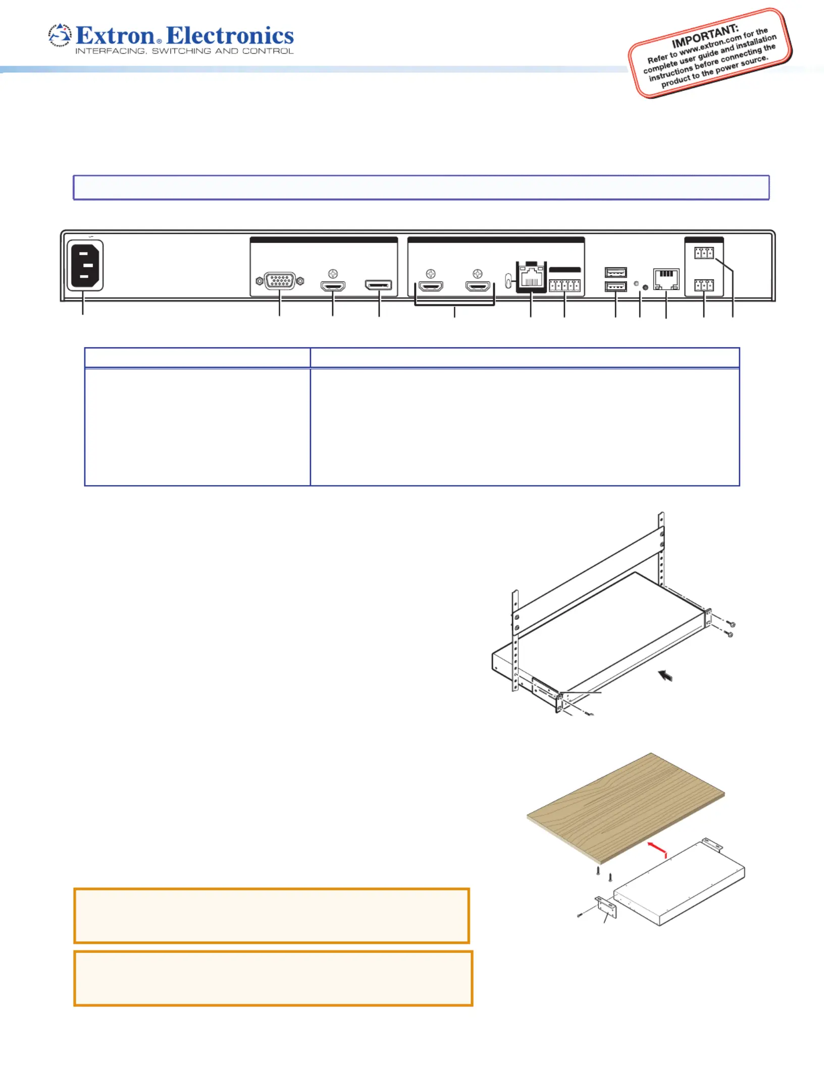
| Bredde: | 445 mm |
| Dybde: | 241 mm |
| Højde: | 44 mm |
| Vægt: | 2400 g |
| Produktfarve: | Sort |
| Kontroltype: | Knapper |
| Pakkevægt: | 3220 g |
| Pakkedybde: | 362 mm |
| Pakkebredde: | 546 mm |
| Pakkehøjde: | 114 mm |
| Understøttede videotilstande: | 480i, 480p, 576i, 576p, 720p, 1080i, 1080p |
| Opbevaringstemperatur (T-T): | -40 - 70 °C |
| Relativ luftfugtighed ved drift (H-H): | 10 - 90 % |
| Relativ luftfugtighed ved opbevaring (H-H): | 10 - 90 % |
| Strømforbrug (typisk): | 37 W |
| Driftstemperatur (T-T): | 0 - 50 °C |
| Maksimal opløsning: | 2560 x 1600 pixel |
| Husmateriale: | Metal |
| Indgangsspænding for vekselstrømsadapter: | 100 - 240 V |
| Frekvens for vekselstrømsadapter: | 50/60 Hz |
| Pakketype: | Kasse |
| Understøttede grafikopløsninger: | 640 x 480 (VGA),800 x 600 (SVGA),1024 x 768 (XGA),1280 x 1024 (SXGA),1280 x 768 (WXGA),1280 x 800 (WXGA),1360 x 768 (WXGA),1366 x 768,1400 x 1050 (SXGA+),1440 x 900 (WXGA+),1600 x 1200 (UXGA),1600 x 900,1680 x 1050 (WSXGA+),1920 x 1200 (WUXGA),2048 x 1080,2560 x 1600 (WQXGA) |
| Certificering: | CE, c-UL, UL, C-tick, FCC Class A, ICES, VCCI, WEEE |
| LED-indikatorer: | Ja |
| Bæredygtighedscertifikater: | RoHS |
| AC (strøm) indgang: | Ja |
| HSMI-indgang: | 1 |
| Antal HDMI-udgange: | 2 |
| Stativ-montering: | Ja |
| Varmeafgivelse: | 81.4 BUT/t |
| Digital vertikal frekvens: | 23.98 - 60 Hz |
| Skalerede opløsninger: | 640 x 480,800 x 600,1024 x 768,1280 x 1024,1280 x 768,1280 x 800,1360 x 768,1366 x 768,1400 x 1050,1440 x 900,1600 x 1200,1600 x 900,1680 x 1050,1920 x 1200 |
| VGA (D-Sub) indgangsporte: | 1 |
| Antal RJ-45-porte: | 2 |
| RS-232 udgangsporte: | 1 |
| Understøttede opløsninger: | 640 x 480\n800 x 600\n1024 x 768\n1280 x 768\n1280 x 800\n1280 x 1024\n1360 x 768\n1440 x 900\n1400 x 1050\n1600 x 900\n1680 x 1050\n1600 x 1200\n1920 x 1200\n2560 x 1600 |
| Rackkapacitet: | 1U |
| Ventilator: | Ja |
| Fjernbetjening brugerflade: | 1 |
| Maksimal pixel ur: | 270 MHz |
Har du brug for hjælp?
Hvis du har brug for hjælp til Extron Annotator 300 stil et spørgsmål nedenfor, og andre brugere vil svare dig
Ikke kategoriseret Extron Manualer


Ikke kategoriseret Manualer
- FCC BBQ
- WEICON
- Mitsubishi
- AddLiving
- Mammotion
- Einhell Bavaria
- Turtle
- iAXBi
- MOOOV
- Stelton
- MGL Avionics
- Dux
- Discovery
- Skylum
- Cayin
Nyeste Ikke kategoriseret Manualer


