Extron DVS 304 DVI D Manual
Extron
Ikke kategoriseret
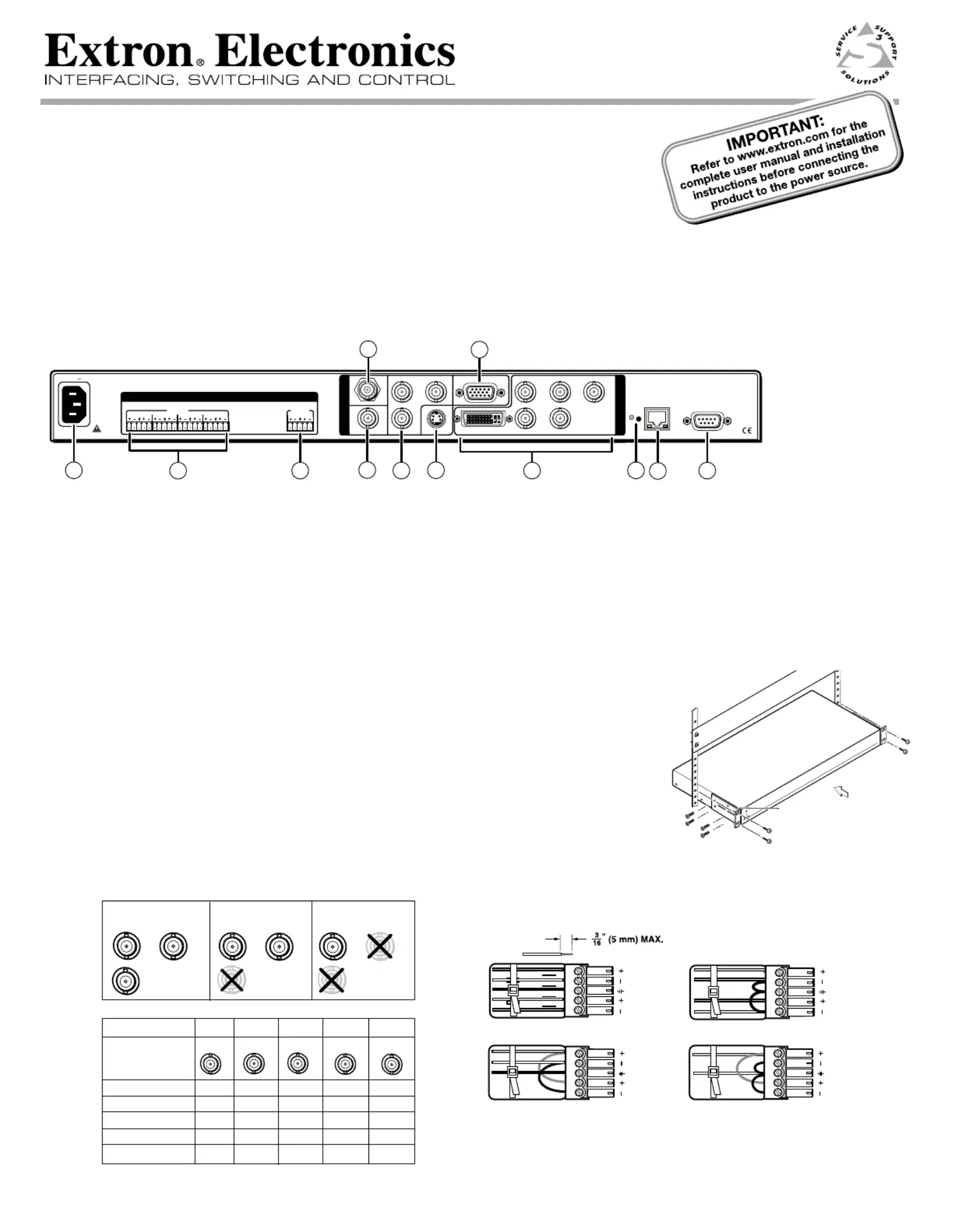
DVS 304 DVI D
| Mærke: | Extron |
| Kategori: | Ikke kategoriseret |
| Model: | DVS 304 DVI D |
| Bredde: | 222 mm |
| Dybde: | 267 mm |
| Højde: | 44 mm |
| Vægt: | 1500 g |
| Produktfarve: | Sort |
| Kontroltype: | Knapper |
| Pakkevægt: | 2150 g |
| Pakkedybde: | 330 mm |
| Pakkebredde: | 356 mm |
| Pakkehøjde: | 102 mm |
| Understøttede videotilstande: | 480p, 576p, 720p, 1080i, 1080p |
| Opbevaringstemperatur (T-T): | -40 - 70 °C |
| Relativ luftfugtighed ved drift (H-H): | 10 - 90 % |
| Format til analogt signal: | NTSC 3.58, NTSC 4.43, PAL, SECAM |
| Strømforbrug (typisk): | 30 W |
| Driftstemperatur (T-T): | 0 - 50 °C |
| Husmateriale: | Metal |
| Indgangsspænding for vekselstrømsadapter: | 100 - 240 V |
| Frekvens for vekselstrømsadapter: | 50 - 60 Hz |
| Certificering: | CE, c-UL, UL, C-tick, FCC Class A, ICES, VCCI Class A |
| LED-indikatorer: | Ja |
| AC (strøm) indgang: | Ja |
| Justering af forstærkning: | Digital |
| Digital vertikal frekvens: | 50 - 120 Hz |
| Skalerede opløsninger: | 640 x 480,1920 x 1200 |
| Antal RJ-45-porte: | 1 |
| Digital horisontal frekvens: | 15 - 100 kHz |
| Rackkapacitet: | 1U |
| Indgangsstrøm til vekselstrømsadapter: | 0.3 A |
| Sync output impedans: | 75 ohm (Ω) |
| DC-forskydning: | 1300 mV |
Har du brug for hjælp?
Hvis du har brug for hjælp til Extron DVS 304 DVI D stil et spørgsmål nedenfor, og andre brugere vil svare dig
Ikke kategoriseret Extron Manualer

11 December 2025

30 November 2025

27 November 2025

26 November 2025

9 November 2025
8 November 2025
6 November 2025

4 November 2025

3 November 2025

2 November 2025
Ikke kategoriseret Manualer
- Dux
- Newline
- HomePilot
- Europalms
- Cateye
- Aligator
- Value
- Edge
- Blaupunkt
- Rothenberger
- Sterling
- ZLine
- Kugoo
- Leitz
- Pro-Lift
Nyeste Ikke kategoriseret Manualer

11 December 2025

11 December 2025

11 December 2025

11 December 2025

11 December 2025

11 December 2025

11 December 2025

11 December 2025

11 December 2025

11 December 2025