1
Product Category
ECM S10 Partition Sensor • Setup Guide
ECM S10 is a pollution degree 2 product with a rated impulse voltage of 330 V. Construction of Control is dened as
“Independently Mounted”. The purpose of the control is considered as an “Operating Control” with Type 1 Action.
The Extron ECM S10 is an eBUS
®
compatible partition sensor. The sensor consists of a transmitter and receiver pair, which are
mounted, face down, in the ceiling on either side of a moveable room partition. The receiver is mounted up to 10 feet (3 m) away
from the transmitter and in direct line of sight. When the partition is open, the receiver detects the IR signal from the transmitter.
When the partition is closed, the IR signal from the transmitter is blocked and the receiver can no longer detect a signal.
The control signal indicating whether the partition is open or closed can be sent through the eBUS port. Alternatively, it can be
sent through the digital output port, which allows communication with Extron IPCP control processors, Extron legacy control
products, or third-party controllers that have digital I/O ports.
Multiple ECM S10 partition sensors can be connected to a single control processor. If the control signal is sent via eBUS, up to
eight partition sensors can be connected to the IPCP control processor.
NOTE: Extron IPCP control processors are the only control processors that have an eBUS port.
If the control signal is sent via the digital port, the number of partition sensors is limited only by the number of digital I/O ports
available on an Extron or third-party control processor.
The receiver is powered through the eBUS port. The transmitter is powered by a 14 VDC cable connected to the receiver. The
transmitter does not have an eBUS port.
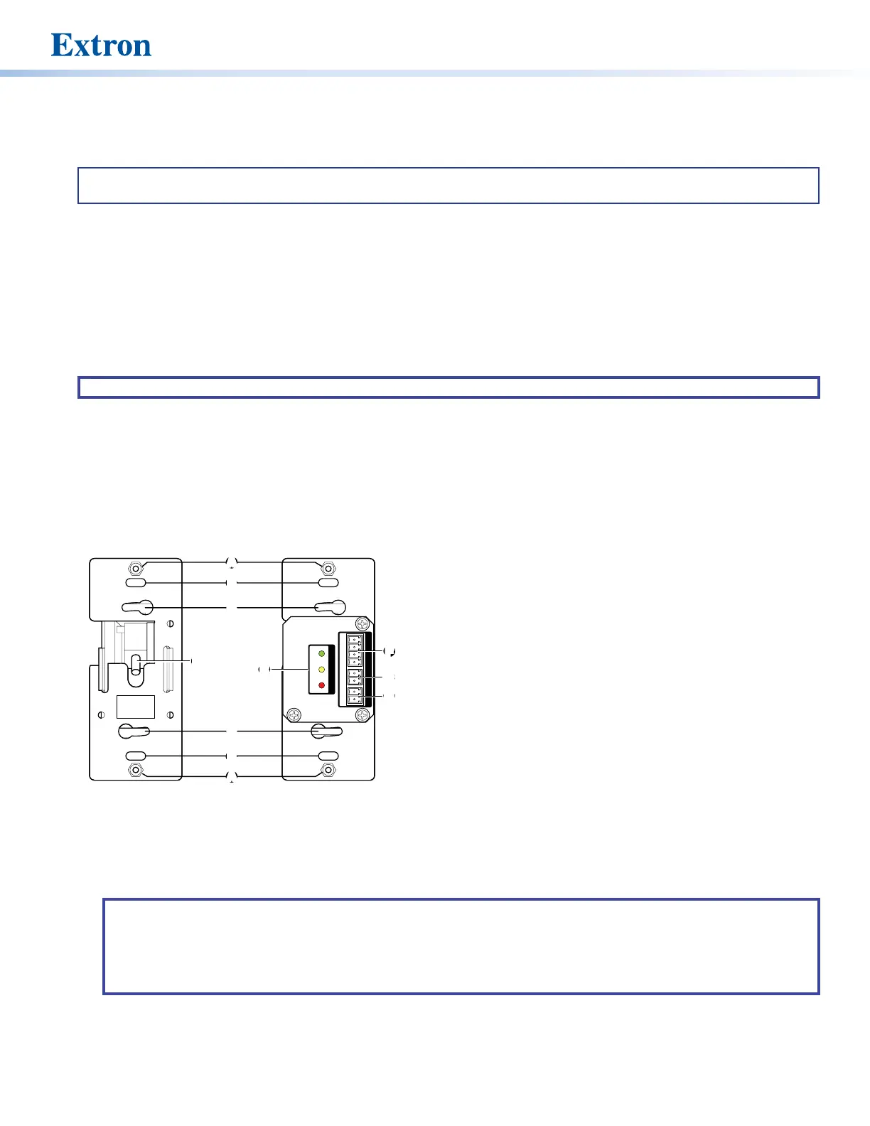
A
Decorator Style Faceplate Cover Mounting Location (2) —
Used to attach the oversized 1-gang decorator style cover.
B
US 1-gang Mounting Slots (2) — Used to mount the device
to any standard US 1-gang junction box. The slots allow minor
alignment adjustments.
C
EU and MK 1-gang Mounting Slots (2) — Used to mount the
device to any standard EU or MK 1-gang junction box. The
slots allow minor alignment adjustments.
D
Transmitter Power Input — A 12-inch (305 mm) pigtail,
terminated with a two-pole captive screw connector accepts
power from the receiver power output (see
G
, below). A
separate cable, connecting the pigtail to the receiver, must be
provided by the user.
E
eBUS Status LEDs — The ECM S10 receiver has yellow, red,
and green LEDs that provide diagnostic information about
the connection, communication, and power status of the
panels. For more information about how the LEDs are used for
troubleshooting see Step 5 — Testing and Troubleshooting
the System on page 12.
F
eBUS Port — This four-pole captive screw connector provides power to the ECM S10 receiver and can also provide
communication between the ECM S10 and an Extron IPCP control processor.
NOTES:
• If the control signal is sent to the control processor by eBUS, cables are connected to all four poles (see Step 2 —
Connecting Cables to the Units on page 6).
• If the control signal is sent to the control processor by digital output port, cables are connected to the +V and G
poles only (see Step 2 — Connecting Cables to the Units).
G
Receiver Power Output — This two-pole captive screw connector provides 14 VDC to the transmitter.
H
Digital Output Port — If the control signal is sent to the control processor by digital output, connect this two-pole captive
screw connector to a Digital I/O port on a control processor.
Panel Features
Rear Panel
STATUS
eBUS +V OUT
D OUT
LINKERROR
COM
ERROR
ID
PWR LOAD = 1.0 W
+V +S -S G14 G GOUT
w
ECM S10 Receiver
M S10 Transmitter
AA
B
B
C
C
B
B
A
A
C
C
EE
F
F
G
G
H
H
DD
Figure 1. Rear Panel Features of ECM S10
Transmitter (left) and Receiver (right)
figure 1